13 Flange Types (ASME B16.5)
Types of Flanges
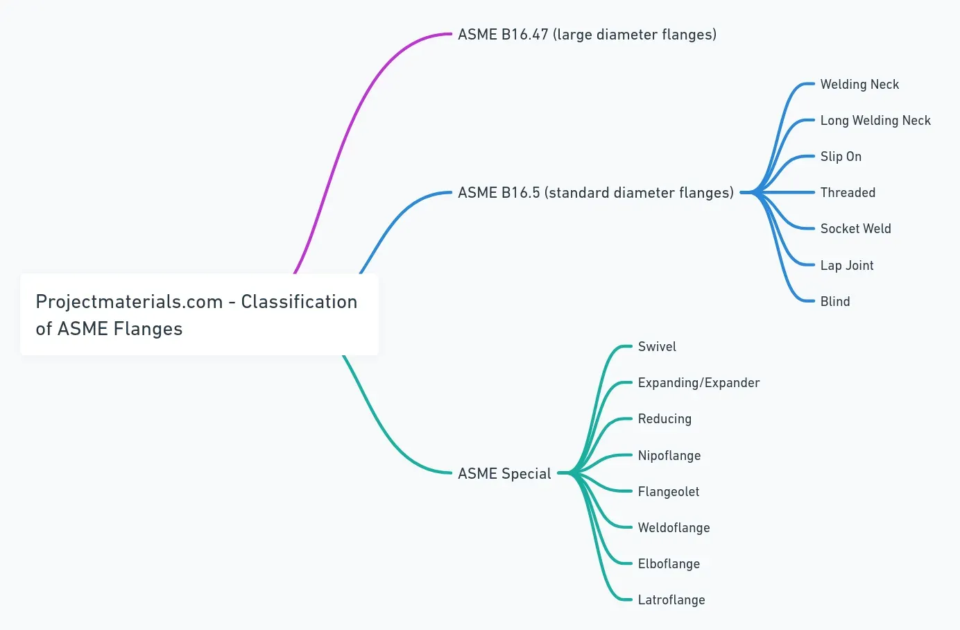
Standard Types (ASME)
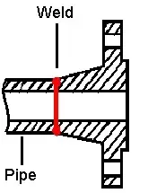
Welding Neck Flange (“WNF”)

The weld neck flange features a tapered hub that provides stress distribution and reinforcement for high-pressure and high/low-temperature applications. The bore matches the pipe ID for unrestricted flow.
| Feature | Description |
|---|---|
| Connection | Single full-penetration V-shaped butt weld |
| Bore | Machined to match pipe ID (smooth flow, no turbulence) |
| Standards | ASME B16.5 (≤24”), B16.47 (>24”) |
| Applications | High P/T, fluctuating conditions, critical services |
Advantages: Strong welded joint; tapered hub reduces stress concentration; allows radiographic inspection; no pressure drops at joint.
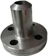
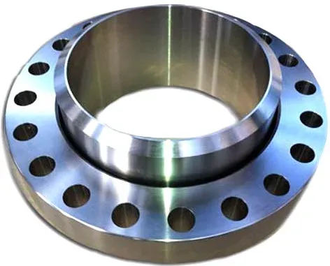
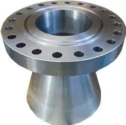
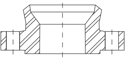
Long Welding Neck (“LWNF”)
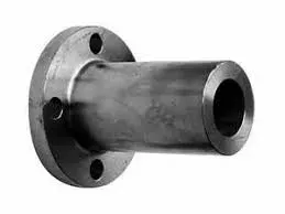
The Long Welding Neck Flange has an extended neck for additional reinforcement in high-stress applications. Used to connect piping to pressure vessels, boilers, and heat exchangers where clearance for insulation is needed.
| Feature | Description |
|---|---|
| Connection | Butt-weld (same as WNF) |
| Variants | Heavy Barrel (HB), Equal Barrel (E) |
| Applications | Vessels, columns, barrels; thermal expansion/contraction zones |
Advantages: Better stress distribution along extended neck; handles piping misalignment; resists vibration and thermal cycling.
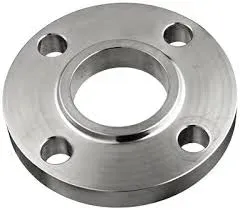
Slip-On Flange
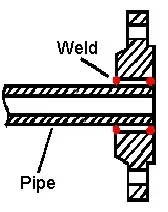
The slip-on flange slides over the pipe and is connected by two fillet welds (inside and outside). Also called “Hubbed Flanges” due to their slim, compact shape. The bore is larger than the pipe OD to allow insertion.
| Feature | Description |
|---|---|
| Connection | Two fillet welds (inside + outside) |
| Bore | Larger than pipe OD (pipe slides in) |
| Applications | Lower P/T, non-critical services (water, HVAC) |
Advantages: Lower cost; easier alignment than WNF; suitable for tight spaces.
Limitations: Lower strength than WNF; not for high P/T or fatigue conditions.
Weld Neck vs. Slip-On
| Aspect | Weld Neck | Slip-On |
|---|---|---|
| Strength | Higher (tapered hub) | Lower |
| Welds | 1 butt weld | 2 fillet welds |
| Cost | Higher | Lower |
| Connection | Pipes + fittings | Pipes only |
| Application | High P/T, critical | Low P/T, non-critical |
Threaded Flange
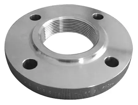
The pipe screws directly into the flange (NPT threads per ASME B1.20.1) without welding. Small seal welds may be added for extra strength.
Sizes: Up to 4” typically. Applications: Low P/T utility services (water, air); mandatory in explosive areas where welding is prohibited.
Socket Weld Flange
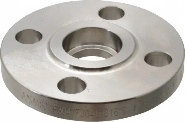
The pipe inserts into the socket and is secured by a single fillet weld on the outside. Per ASME B31.1, insert pipe to bottom of socket, then lift 1.6 mm before welding (allows for weld solidification positioning).
Applications: Small-size, high-pressure piping. Not for corrosive fluids-the gap between pipe end and socket shoulder is prone to crevice corrosion.
Strength: Similar static strength to slip-on, but higher fatigue strength (single weld vs. double).
Lap Joint Flange
Lap joint flanges are always used with a stub end. The flange slips over the pipe and seats on the stub end’s flanged portion; bolts hold the assembly together.

Cost-saving design: Use carbon steel lap joint flange with stainless/nickel alloy stub end-only the stub end (in contact with fluid) needs high-grade material. The flange can rotate freely for easy bolt alignment.
Blind Flange
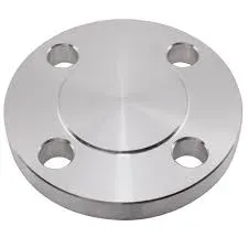
Blind flanges have no center hole-used to seal pipeline ends, valves, or pressure vessels. Must withstand full system pressure plus bolting forces. Easy to unbolt for pipeline access (also used as pressure vessel manholes).
Special Types (ASME)
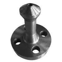
Nipoflange
A Nipoflange creates 90° branch connections-a single forged piece combining a weld neck flange and a Nipolet. Weld the Nipolet portion to the run pipe; bolt the flange to the branch pipe. Available in reinforced variants for higher strength.
Materials: A105, A350, A182 (stainless, duplex), nickel alloys.
Weldoflange
A Weldoflange combines a weld neck flange with a branch fitting-weld directly to the run pipe for a reinforced branch connection. Eliminates separate tee + flange combinations; space-saving for congested areas.
Applications: High P/T branch connections in oil & gas, petrochemical, power generation.
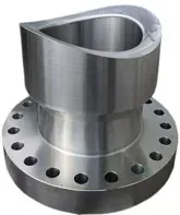
Elboflange
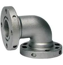
An Elboflange integrates an elbow + flange into one piece-changes flow direction while providing a flanged connection. Reduces fittings and welds; ideal for tight spaces.
Applications: Connecting piping to compressors, reactors, tanks, boilers, turbines where direction change + flange connection is needed.
Latroflange
A Latroflange combines a lateral tee + flange-creates angled branch connections (typically 45°) with a flanged outlet. Reduces turbulence vs. 90° branches; easier equipment attachment.
Applications: Process instrumentation connections, bypass lines, flow distribution systems.
Swivel Flange
Swivel flanges rotate freely on the pipe for bolt hole alignment-required for large-diameter pipelines, subsea/offshore installations, and shallow water pipe works.
Availability: All standard flange shapes (WN, SO, LJ, SW); sizes 3/8” to 60”; Classes 150-2500. Materials: A105, A182 F1/F5/F9/F91, A182 F304/F304L/F316/F316L.
Expanding and Reducing Flanges
Expander flanges increase pipe bore; reducer flanges decrease pipe bore. Both limited to 1-2 size changes maximum-for larger changes, use buttweld reducer + standard flange.
Materials: A105, A350, A182. Faces: RF, FF per ASME B16.5.
European Types of Flanges (EN/DIN/ISO)
European flanges follow EN 1092-1 (superseding older DIN standards) with pressure ratings in PN (Pressure Nominale, bars) vs. ASME Class system.
| Standard | Flange Types |
|---|---|
| EN 1092-1 | Type 01 (plate), Type 02 (loose plate), Type 05 (blind), Type 11 (weld neck), Type 13 (threaded) |
| DIN | DIN 2501 (bolt/face dimensions), DIN 2631-2638 (weld neck), DIN 2576 (slip-on) |
| ISO 7005-1 | Mirrors EN 1092-1 for global compatibility |
Dimensions: DN 10 to DN 4000. Materials: Carbon steel, stainless steel, alloys.
See also:
- EN 1092 Weld Neck Flange Sizes
- EN 1092 Blind Flange Sizes
- EN 1092 Threaded Flange Sizes
- EN 1092 Plate Flange Sizes
Flange Selection Criteria
| Factor | Considerations |
|---|---|
| Pressure/Temperature | WNF for high P/T; SO for moderate conditions |
| Fluid properties | Corrosive → stainless/alloy; crevice-sensitive → avoid SW |
| Assembly/Maintenance | LJ for frequent disassembly; threaded for no-weld zones |
| Space/Weight | Threaded or SW for compact installations |
| Cost | SO < WNF; LJ + stub end reduces high-grade material use |
| Safety | WNF for critical services; verify correct P/T rating |
| Installation | Threaded where welding prohibited; swivel for alignment |
| Standards | ASME B16.5/B16.47 (US), EN 1092-1 (Europe) |
Leave a Comment
Have a question or feedback? Send us a message.
Previous Comments
Such a great blog and I really appreciate to read this blog.
informative blog, can you make a blog on its application of carbon flanges. ms flanges
Thank you very much. Your blog helped me a lot during my research!
a very good and informative blog thanks for this blog waiting for you to make a blog on different types of fittings .
Good knowledge