Drilling Equipment: Rigs & Systems
Drilling Equipment in Oil & Gas
What Is Oil & Gas Drilling
Drilling in oil and gas means boring holes into the Earth’s subsurface to find and produce hydrocarbon resources, mainly crude oil and natural gas. It sits squarely in the upstream segment: you search for reservoirs, drill exploratory wells, and then drill and operate the production wells that bring hydrocarbons to surface.
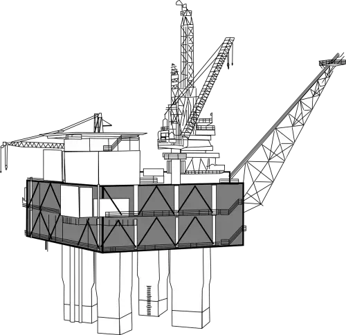 Offshore Oil Rig
The work follows a well-defined sequence: site preparation, drilling, casing and cementing, hydrocarbon testing, and well completion. Directional and horizontal drilling have opened up reservoirs that were previously uneconomic, letting operators drain large areas from a single surface pad.
Drilling Process: Key Steps
Site Selection and Preparation
Before anything moves on site, geologists and reservoir engineers pore over seismic surveys and offset well data to pick the best surface location and target depth.
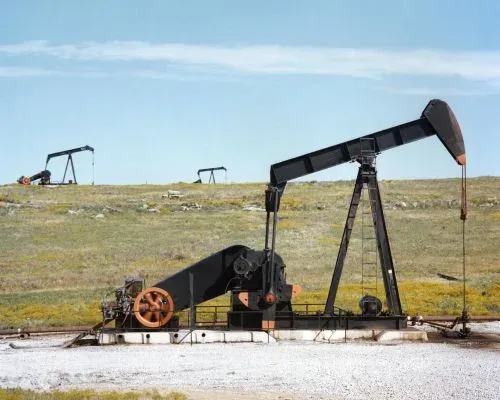 oil pump jacks
Site Selection comes down to subsurface geology (reservoir depth, hydrocarbon type, estimated reserves) weighed against surface logistics (road access, water supply, proximity to pipelines, and regulatory constraints). In environmentally sensitive areas, this trade-off often dictates directional wells from a remote pad rather than a vertical well directly above the target.
Site Preparation means clearing and leveling the ground, building access roads, constructing the drilling pad (strong enough to carry the rig and all ancillary equipment), and installing containment berms, water supply lines, and waste management systems. On a busy land rig, you can have 40-50 truck loads of equipment arriving over a few days, so the pad had better be ready.
Licensing and Permits: Obtain necessary environmental and drilling permits before mobilization.
Drilling Rig Setup
Rig-up follows a well-rehearsed sequence. The mast, sub-structure, drill string, BOPs, and ancillary equipment arrive by truck (land) or supply vessel (offshore). The crew erects the rig floor and sub-structure first, then raises the mast or derrick. Next come the mud system (tanks, pumps, shale shakers), power generation, and the BOP stack. Each system is pressure-tested and function-tested before spudding.
Once every system checks out, the drill bit goes in the hole and drilling begins.
Drilling the Well
Spudding In (the first bit-to-ground contact) confirms the exact well location and creates the pilot hole. It is a milestone: the rig transitions from setup to active drilling.
Drilling the Main Hole proceeds in intervals. After each interval, casing is run and cemented before drilling resumes with a smaller bit diameter. The conductor casing goes in first (shallow depth, large diameter), followed by surface, intermediate, and finally production casing strings.
Circulating Drilling Fluid (“mud”) is continuous throughout. The mud cools and lubricates the bit, carries cuttings to surface, and exerts hydrostatic pressure on the formation to prevent kicks. Mud engineers adjust weight, viscosity, and chemistry on the fly based on formation conditions. Get this wrong and you either fracture the formation (lost circulation) or take a kick.
Adding Drill Pipes (“making a connection”) happens every 30 feet (single) or 90 feet (stand). The driller stops rotation, breaks out the top drive, adds a new joint, and makes up the connection. On a fast well you might make 100+ connections, so anything that speeds up this process (top drive vs. kelly, automated pipe handling) saves real money.
Logging and Testing run throughout. Wireline logs measure resistivity, porosity, gamma ray, and sonic properties; LWD/MWD tools give real-time formation data while drilling. Core samples provide direct evidence of rock and fluid properties. All of this data feeds into the decision: is the target zone worth completing?
Reaching the Target Formation triggers detailed evaluation: further logging, drill-stem tests (DSTs), and pressure measurements to characterize the reservoir before committing to completion.
Casing and Cementing
Casing and cementing convert a raw borehole into a structurally sound, zonal-isolated well.
Casing is run in stages. Conductor casing (typically 30” or 20”) stabilizes the topsoil. Surface casing (13-3/8” or 9-5/8”) protects freshwater aquifers (regulators watch this one closely). Intermediate casing handles troublesome zones (lost circulation, abnormal pressure). Production casing (7” or 5-1/2”) lines the reservoir section and provides the conduit for hydrocarbons to surface.
Cementing fills the annulus between each casing string and the borehole wall. The cement bonds the casing to the formation, isolates zones to prevent cross-flow, protects against corrosion, and seals the wellbore against hydrocarbon leaks. The cement mix is formulated for the specific downhole temperature, pressure, and chemistry. A deep, hot well needs retarders; a shallow, cold well needs accelerators. Cement is pumped down the casing, around the shoe, and up the annulus from bottom to top. Once set, it forms a permanent seal.

Well Evaluation and Testing
Well evaluation tells you whether the reservoir is worth completing, and how to complete it. Logging, core analysis, and flow testing each provide different pieces of the puzzle.
Well Logging uses instruments lowered into the wellbore (wireline) or integrated into the BHA (LWD/MWD) to measure formation properties. Common log types:
| Log Type | What It Measures | Purpose |
|---|---|---|
| Resistivity Logs | Resistivity of rock and fluids | Identify hydrocarbon-bearing formations |
| Porosity Logs | Porosity of the rock | Indicate the rock’s ability to hold hydrocarbons |
| Acoustic Logs | Speed of sound through rock | Provide density and elastic property information |
| Gamma Ray Logs | Natural radioactivity | Distinguish rock types; identify shale and sandstone layers |
| Imaging Logs | Detailed wellbore wall images | Identify rock texture, fractures, and geological features |
Core Sampling retrieves cylindrical rock samples for lab analysis of porosity, permeability, and fluid saturation. Nothing beats holding the actual rock in your hand; logs can mislead, but cores don’t lie.
Well Testing temporarily produces the well to measure reservoir pressure, flow rate, and fluid composition. Pressure transient analysis (build-up and drawdown tests) reveals permeability and reservoir extent. Production tests quantify flow rates of oil, gas, and water.
Formation Evaluation integrates all of this (logs, cores, and test data) into a reservoir model that drives completion design, well placement, and field development planning.
Well Completion
Completion turns a drilled hole into a producing well. The specific approach depends on reservoir pressure, fluid properties, formation stability, and economics.
The typical sequence for a cased-hole completion:
- Casing and Cementing (already covered above): production casing is run and cemented across the pay zone.
- Perforating: shaped charges fired from a perforating gun punch holes through casing and cement, creating flow paths from reservoir to wellbore. Shot density and phasing matter: too few perfs choke the well; too many weaken the casing.
- Production Tubing: a smaller-diameter string (typically 2-7/8” to 4-1/2”) hung inside the casing isolates production flow and protects the casing from corrosive well fluids.
- Wellhead and Christmas Tree: the wellhead provides the surface pressure barrier; the tree (an assembly of valves and chokes) controls flow. On a high-pressure gas well, the tree rating can exceed 15,000 psi.
- Stimulation: hydraulic fracturing (shale/tight formations) or matrix acidizing (carbonates) to improve near-wellbore permeability and boost production rates.
- Initial Production Test: flow rates, pressures, and fluid composition are measured to set the production strategy.
Open hole completions skip the production casing in the reservoir section and are used where the formation is competent enough to stand open. Cased-hole completions are far more common because they give better zonal control and the ability to re-enter and workover the well later.
Production
Production is where the investment pays off: hydrocarbons flow from the reservoir, through the wellbore, and into processing facilities.
| Recovery Stage | Method | Typical Recovery Factor |
|---|---|---|
| Primary | Natural reservoir pressure, artificial lift (pump jacks, ESPs, gas lift) | 10-15% of OOIP |
| Secondary | Waterflooding, gas re-injection to maintain pressure | 20-40% of OOIP |
| Tertiary (EOR) | Thermal (steam), CO2 injection, chemical (surfactant/polymer) flooding | Additional 15-25% |
Every well eventually declines. Managing that decline (through workovers, infill drilling, artificial lift optimization, and EOR) is where production engineers earn their keep. Once at surface, crude oil and gas are separated, treated (removal of water, H2S, CO2), and transported via pipeline or tanker to refineries and gas plants.
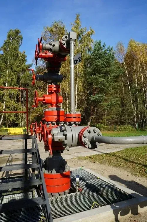 Crude Oil Production
Well Abandonment and Site Reclamation
When a well reaches the end of its economic life, it must be permanently plugged and abandoned (P&A). The crew pulls production equipment, sets cement plugs at multiple depths to isolate all permeable zones and protect groundwater, then cuts the casing below ground level and welds on a cap. Regulatory agencies specify minimum plug depths and cement volumes; cutting corners here creates long-term environmental liability.
Site reclamation follows: remove infrastructure, remediate contaminated soil, and revegetate with native species. In many jurisdictions, operators must post bonds to guarantee reclamation is completed.
Key Takeaway: Oil and gas drilling is a multi-stage process (from site selection through well completion) that relies on specialized equipment including drilling rigs, drill strings, mud systems, BOPs, and power/hoisting/rotary systems. Each component must be carefully selected and maintained for safe, efficient, and environmentally responsible operations.
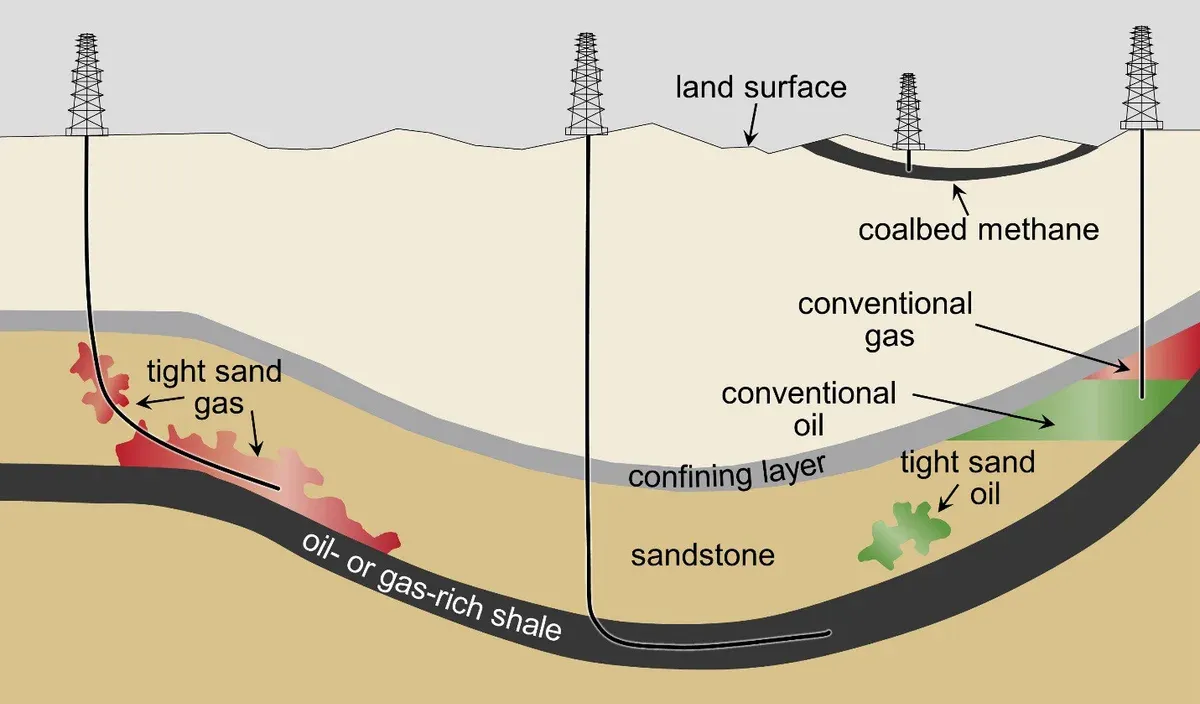
Categorization of Drilling Methods
Vertical Drilling
Vertical drilling is the simplest and cheapest method: a straight hole down to a reservoir directly below the surface location. It remains common for conventional reservoirs with straightforward geology, but its limited reservoir contact makes it a poor choice for tight formations or thin pay zones.
 Horizontal vs. Vertical Well Drilling
Horizontal Drilling
A horizontal well kicks off from vertical, builds angle through a curve section, and then runs laterally through the pay zone, sometimes for 10,000+ feet. The result is far greater reservoir contact than a vertical well. Horizontal drilling made shale plays economic: a vertical Bakken well might produce 50 bbl/d, while a horizontal well with multi-stage fracs can produce 500-1,000 bbl/d from the same formation.
Directional Drilling
Directional drilling steers the bit along a planned trajectory that may include curves, tangent sections, and multiple targets. Offshore, it is standard practice; a single platform can drill 40+ directional wells to drain an entire field. Onshore, directional drilling lets you reach reservoirs beneath rivers, towns, or protected areas from a pad located on less sensitive ground. The directional driller uses mud motors, rotary steerable systems, and MWD surveys to hit targets that can be miles from the surface location.
Fracturing (Fracking Shale Gas)
Hydraulic fracturing (“fracking”) cracked open the shale revolution. Shale has near-zero permeability, and without fracturing, hydrocarbons simply cannot flow to the wellbore at commercial rates.
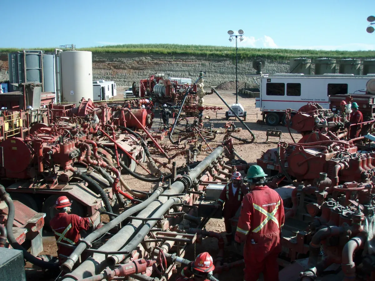 Hydraulic Fracturing Operation
The process: drill a horizontal lateral through the target shale, isolate sections with packers or plug-and-perf, then pump a slurry of water, sand (proppant), and chemical additives at pressures high enough to crack the rock (typically 5,000-10,000 psi at surface). The proppant holds the fractures open so gas and oil can flow.
Fracking turned the Marcellus, Permian, and Eagle Ford into some of the most productive basins in the world. It also generates legitimate environmental debate around water use, induced seismicity, and methane emissions. The industry response has been tighter well construction standards, recycled frac water, reduced-emission completions, and continuous monitoring.
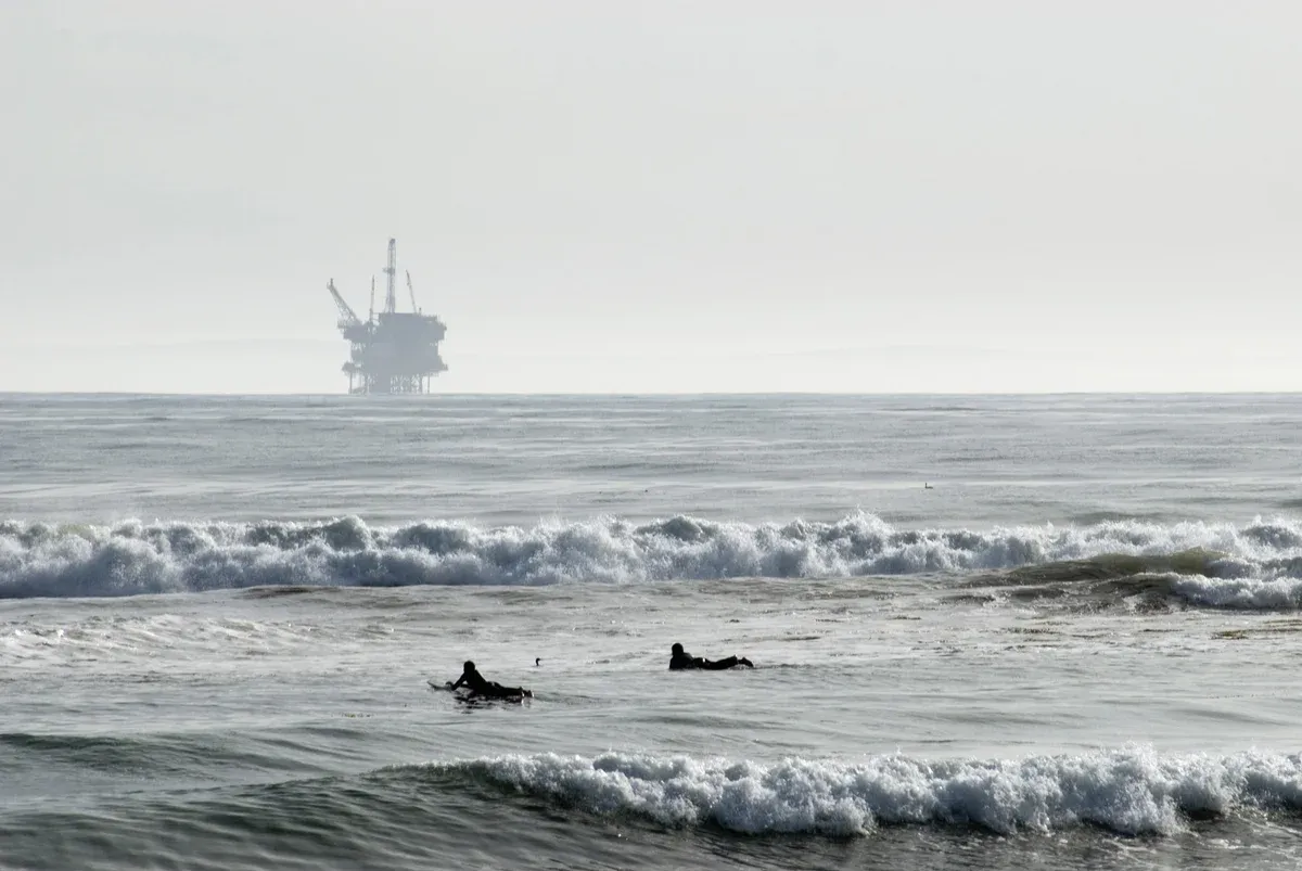
Offshore Drilling
Offshore drilling accesses reservoirs beneath the seabed, from shallow continental shelves to ultra-deepwater (10,000+ ft water depth).
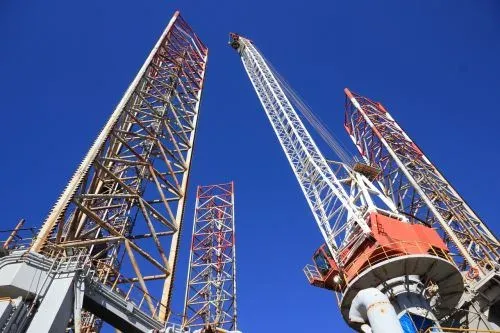 Offshore Drilling Rigs
Platform selection depends on water depth and environment:
| Platform Type | Water Depth | Notes |
|---|---|---|
| Fixed platform | Up to ~1,500 ft | Steel jacket or concrete gravity base; permanent |
| Compliant tower | 1,000-3,000 ft | Flexible structure; absorbs wave energy |
| Jack-up rig | Up to ~400 ft | Legs lowered to seabed; mobile, used for exploration |
| Semi-submersible | 1,000-10,000 ft | Floats on pontoons; anchored or DP; harsh environments |
| Drillship | 1,000-12,000+ ft | Ship-shaped; DP; ultra-deepwater capability |
Offshore operations face unique challenges (weather windows, supply logistics, emergency evacuation, and strict environmental regulations) but they access some of the world’s largest remaining hydrocarbon reserves.
Choosing the Right Method
The drilling method is driven by geology, economics, and surface constraints. Vertical wells are cheapest but limited in reservoir contact. Horizontal wells cost 2-3x more but often produce 5-10x the hydrocarbons from tight formations. Directional drilling is essential offshore (multi-well platforms) and wherever the surface location cannot sit directly above the target. Fracking extends beyond shale; it is also used for EOR in conventional reservoirs and for creating underground gas storage cavities. Offshore development increasingly relies on subsea tiebacks, connecting satellite wells to existing platforms to reduce capital cost per barrel.
Equipment for Drilling Operations
Drilling Rig
The drilling rig is the integrated machine that makes everything happen. It houses the hoisting, rotary, circulation, and power systems plus the crew quarters and safety equipment.
 Types of Offshore Oil and Gas Structures
Types of Drilling Rigs
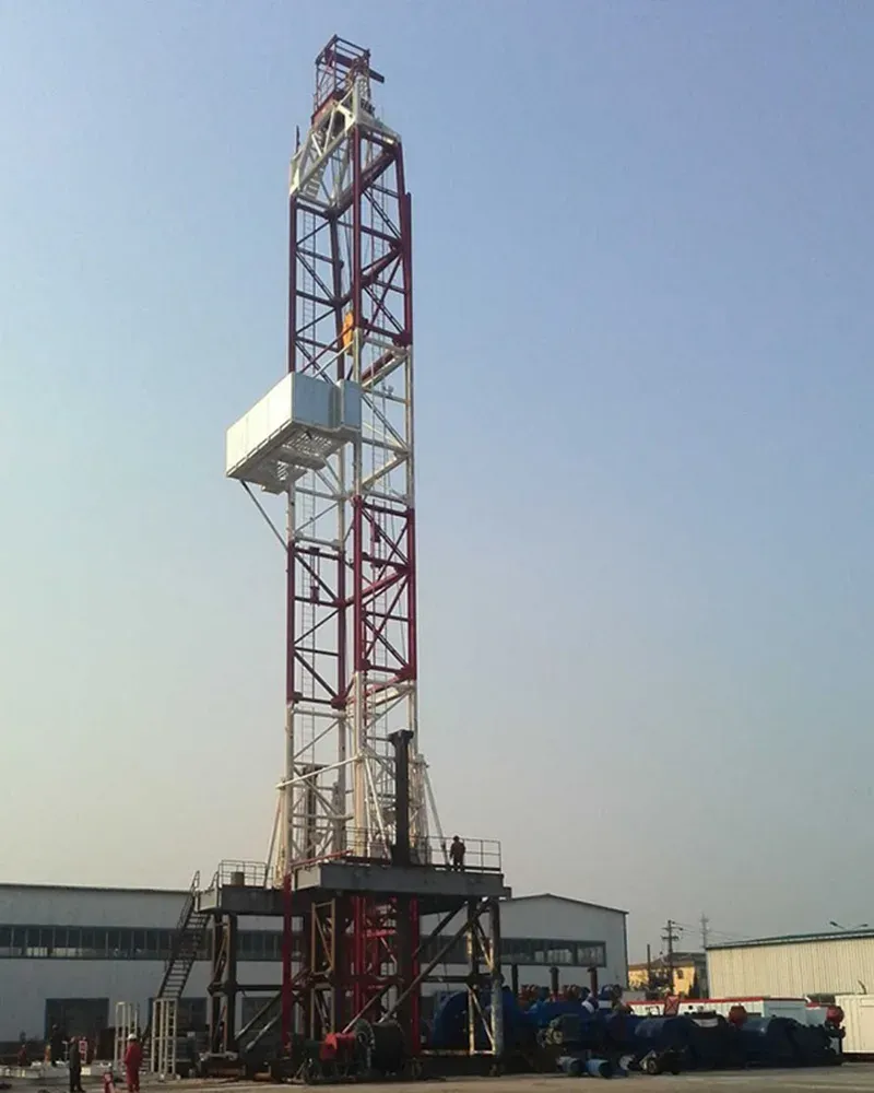
Land Rigs range from small workover units to 3,000-hp AC rigs capable of drilling 25,000+ ft wells. They are trucked to location and rigged up in days. Rig selection depends on target depth, expected pressures, and hole sizes.
 Drilling Rig (Land)
Offshore Rigs (jack-ups for shallow water with legs on seabed, semi-submersibles for deepwater floating with anchors or DP, and drillships for ultra-deepwater with DP) were covered in the offshore drilling section above.
Main Components of a Drilling Rig
The table summarizes the main equipment used in land and offshore drilling rigs. Each component is reviewed more in detail in the following chapters.
| Equipment | Function |
|---|---|
| Drill Rig | Houses the overall drilling operation; including the derrick, mast, and drill floor. |
| Drill Bit | Cuts through the earth; vary in type such as roller cone, diamond, and PDC. |
| Drill Pipe | Connects surface equipment to the drill bit; allows for drilling fluid flow and bit rotation. |
| Mud System | Circulates drilling fluid to cool the drill bit, remove cuttings, and maintain well pressure. |
| Blowout Preventer (BOP) | Controls unexpected pressure surges; required for well safety. |
| Top Drive System | Drives the rotation of the drill string from the top, enhancing drilling efficiency and safety. |
| Drawworks | Main hoisting machinery for lifting/lowering the drill string. |
| Casing | Steel pipe are installed to stabilize the wellbore. |
| Cementing Equipment | Used for mixing and pumping cement for wellbore stabilization. |
| Mud Pumps | Pumps drilling fluid into the drill string, facilitating its circulation. |
| Shale Shaker | Separates drill cuttings from the drilling fluid with a vibrating screen. |
| Desander/Desilter | Removes sand and silt from drilling fluid to further clean it for recirculation. |
| Drill Floor | The operational area for handling the drill string and conducting drilling activities. |
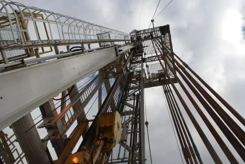
Mast (or Derrick)
The mast is the tall steel framework that supports the crown block, traveling block, and the entire hoisting system. It must carry the full weight of the drill string and casing. On a deep well, that can exceed 500 tons.
 Mast (or Derrick)
Mast height determines how many joints of pipe can be racked as “stands” during trips (pulling pipe out and running it back in). A taller mast means longer stands and faster trips. On land rigs, the mast is typically laid down for transport and raised hydraulically on location. Offshore derricks are permanent structures rated for the maximum expected hook load plus a safety factor.
Drill Floor
The drill floor is where the action happens. It sits directly above the wellbore and holds the rotary table (or top drive), drawworks, iron roughneck, and the driller’s console.
 Drill Floor for Drilling Rigs
On a modern rig, the iron roughneck handles pipe make-up and break-out mechanically, keeping hands off the connections. The doghouse (driller’s cabin) gives the driller line-of-sight to the floor plus digital readouts of WOB, RPM, torque, mud flow, and pit volume. Good drill floor layout directly affects safety and trip speed: the fewer steps between the rotary and the pipe rack, the faster the crew works.
Drill String
Comprises the drill pipe, heavy-weight drill pipe, drill collars, and the drill bit. It is used to drill down into the earth and circulate drilling fluid. Read below for more details.
Drill Bit
The drill bit is the business end of the string; it cuts rock.
 Drill bits
| Bit Type | Mechanism | Best For |
|---|---|---|
| Roller cone (tricone) | Teeth/buttons crush and scrape rock | Soft to medium formations; versatile |
| PDC (polycrystalline diamond compact) | Fixed cutters shear rock | Medium to hard formations; high ROP |
| Natural/synthetic diamond | Grinding action | Very hard, abrasive formations |
PDC bits dominate modern drilling: they have no moving parts, last longer, and drill faster than tricones in most formations. Bit selection is guided by the IADC code system, which classifies bits by design, cutting structure, and formation suitability. All modern bits have nozzles for drilling fluid to cool the cutters, flush cuttings, and maintain gauge (borehole diameter).
Rotary Table or Top Drive
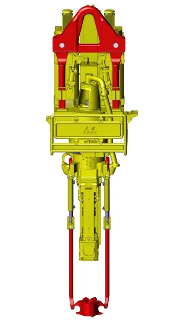 Rotary Table or Top Drive
Rotary Table is the traditional system. A motor-driven table on the rig floor grips the kelly (a square or hex pipe) via a kelly bushing and turns it. The kelly rotates the entire drill string. Simple and reliable, but every connection requires breaking out the kelly, which costs time.
Top Drive is the modern standard. A motorized unit mounted on the mast that directly rotates the drill string from above. It drills 90-ft stands (three joints at a time vs. single joints with a kelly), eliminates kelly handling, and gives the driller precise control over torque and RPM. Top drives also allow back-reaming while tripping, which is critical in sticky hole conditions. Nearly every new rig built in the last 20 years has a top drive.
Mud System
Includes the mud pumps, mud tanks, and drilling fluid (“mud”) treatment equipment. Drilling fluid is circulated down the drill string to cool the drill bit, carry cuttings to the surface, and stabilize the wellbore walls. Read below for more details.
 Mud System
Blowout Preventer (BOP)
The BOP stack sits on top of the wellhead and is the last line of defense against an uncontrolled well. Learn more about Blow-out preventer Systems (BOP) in this dedicated article.
 BOP Blow Out Preventers
Power Generation
Diesel generators or gas turbines supply the 1,000-3,000+ hp that a rig demands. Power systems are covered in detail below.
Drill String
The drill string is the assembly of tubular components that connects the surface equipment to the drill bit. It transmits rotation, carries drilling fluid, and provides weight on bit.
 Drill String
| Component | Function |
|---|---|
| Drill Pipe | The main sections of the pipe comprise the length of the string, providing the pathway for drilling fluids and enabling bit rotation. |
| Drill Collars | Thick-walled, heavy tubes near the drill bit add weight for drilling and stabilize the drill string. |
| Heavy Weight Drill Pipe (HWDP) | Acts as a transitional section between the drill pipe and drill collars, providing additional weight and stiffness. |
| Drill Bit | The cutting tool at the bottom of the string is available in various types for different formations. |
| Stabilizers | Center the drill string in the borehole, reduce vibration, and maintain hole direction. |
| Kelly or Top Drive | The uppermost section of the drill string transmits rotational force to the string and bit (Kelly for rotary table rigs, Top Drive for others). |
| Subs | Short sections of pipe are used to connect components of the drill string that cannot be directly connected due to differing thread types or sizes or to adjust the length of the drill string. |
| Jar | A mechanical device used to deliver an upward or downward jarring impact to free stuck components. |
| Reamer | Used to enlarge the borehole diameter or smooth out irregularities in the drilled hole. |
| Shock Sub | Absorbs and dampens vibrations and shock loads transmitted through the drill string. |
| Float Valve | Prevents backflow of drilling fluids, protecting the drill string and surface equipment from high-pressure zones. |
Components of the Drill String
Drill Pipe makes up the bulk of the string: long steel tubes (typically 4-1/2” or 5” OD for land wells) that transmit rotation and circulate mud. Grades range from E-75 to S-135, with higher grades for deeper, higher-stress wells. Learn more about OCTG API 5CT drill pipes.
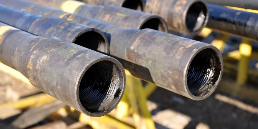 OCTG drill pipes
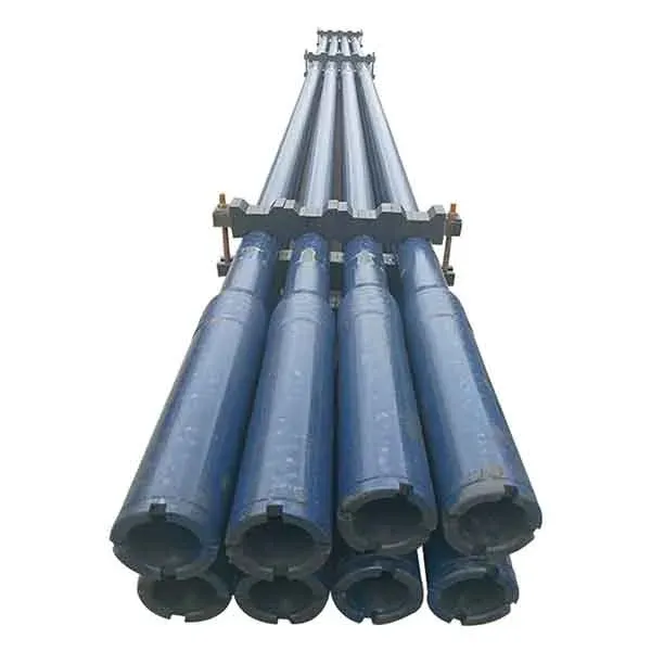
Drill Collars
Drill collars are thick-walled, heavy steel tubes that sit just above the bit in the bottom hole assembly (BHA). Their primary job is simple: put weight on the bit so it cuts rock. A typical 8” OD collar weighs about 147 lb/ft vs. ~20 lb/ft for standard drill pipe.
 J-lay collars forged
Beyond WOB, collars stiffen the BHA to maintain wellbore trajectory and dampen vibrations. Non-magnetic collars (Monel or austenitic stainless) are used in the MWD/LWD section to avoid interfering with directional surveys. Spiral-groove collars reduce the risk of differential sticking in permeable zones where the collar can become embedded in the mud cake.
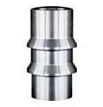
Heavy Weight Drill Pipe (HWDP)
HWDP bridges the stiffness gap between standard drill pipe and drill collars. Without it, the abrupt transition from a flexible pipe to a rigid collar creates a stress concentration point, and that is exactly where fatigue failures occur.
 Heavy Weight Drill Pipe (HWDP)
HWDP has thicker walls and a center upset (enlarged mid-section) that concentrates weight and adds stiffness gradually. In directional wells, a string of HWDP above the collars reduces buckling and improves torque transfer to the bit.
Drill Bits
The cutting tool at the end of the drill string. Different bit types suit different formations; see the drill bit section above for details.
Drilling Stabilizers
Stabilizers center the BHA in the borehole. Their blade contact with the wellbore wall controls lateral vibration, maintains hole direction, and improves cuttings transport by keeping the annulus uniform.
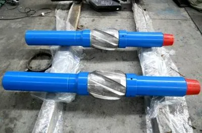 Drilling Stabilizers
In directional drilling, stabilizer placement is critical because the spacing between near-bit and string stabilizers determines whether the BHA builds angle, drops, or holds. Blades are straight or spiral, made from high-strength steel with tungsten carbide hard-facing to resist abrasive formations.
Subs
“Subs” (substitutes) are short, thick-walled adapters that solve thread mismatches and add specific functions to the drill string.
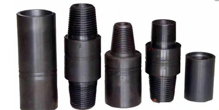 Drilling Subs
| Sub Type | Purpose |
|---|---|
| Crossover sub | Connects components with different thread types or sizes |
| Lift sub | Provides a shoulder for safe lifting of tools and BHA components |
| Saver sub | Sits at top of string to absorb wear from repeated make/break cycles |
| Float sub | One-way valve preventing backflow of drilling fluid |
Kelly or Top Drive
Already covered under the Rotary Table or Top Drive section above. In short: kelly systems are older, cheaper, and slower; top drives are standard on modern rigs for their speed, safety, and directional drilling capability.
Functions of the Drill String
The drill string performs four jobs simultaneously: it transmits rotation from surface to bit, circulates drilling fluid down through the string and up the annulus, maintains hydrostatic pressure on the formation (well control), and, with MWD/LWD tools in the BHA, transmits real-time directional surveys and formation data to surface. Drill string design (pipe grade, collar weight, HWDP placement, stabilizer spacing) is tailored to each well’s depth, expected pressures, hole geometry, and directional plan.
Drilling Fluid System (“Drilling Mud”)
The drilling fluid system circulates mud down the drill string, out the bit nozzles, and back up the annulus to surface. Mud does four things at once: cools/lubricates the bit, carries cuttings to surface, exerts hydrostatic pressure to control the formation, and stabilizes the borehole wall. The equipment that makes this happen:
Components of the Drilling Fluid System
Mud Pumps
Mud pumps are large reciprocating pumps (triplex is standard) that generate the flow rate and pressure to circulate drilling fluid through the entire system. Typical operating pressures range from 3,000-7,500 psi, with flow rates up to 1,200+ gpm.
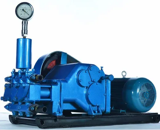 Mud Pumps
A rig usually has two or three mud pumps; redundancy matters here, because losing circulation means losing well control. Pumps are driven by electric motors (AC rigs) or diesel engines (mechanical rigs) and are among the hardest-working equipment on the rig.
Mud Tanks
Mud tanks are the open-top steel compartments that store, mix, and condition drilling fluid.
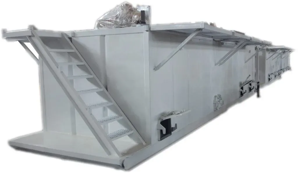 Mud Tanks
A typical rig has a series of interconnected tanks: suction tanks (feed the pumps), mixing tanks (where additives are blended in), settling tanks (where solids drop out), and reserve/trip tanks. Each tank has agitators to keep solids in suspension. Monitoring pit volume is one of the primary kick-detection methods: a gain in pit level means formation fluid is entering the well.
Shale Shakers
Shale shakers are the first line of solids control. Mud returning from the wellbore flows over vibrating screens that separate cuttings from the liquid phase.
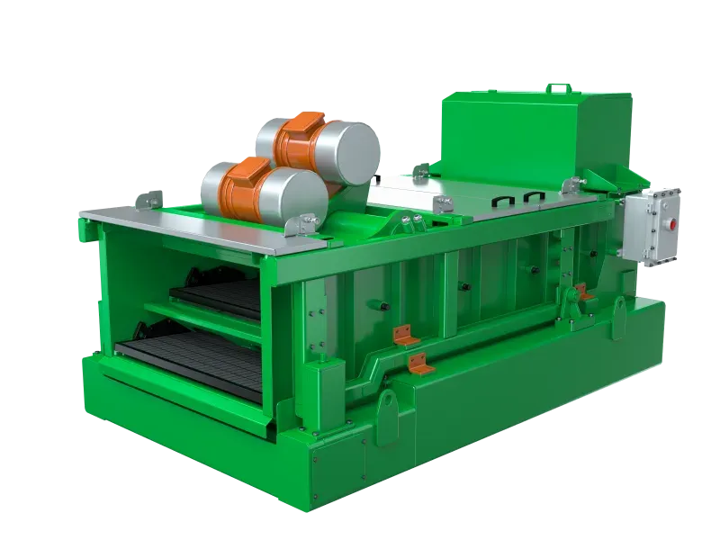 Shale Shakers
Screen mesh size is the key variable: too coarse and fine solids pass through (degrading mud properties); too fine and the screens blind off, dumping good mud over the back with the cuttings. Linear-motion shakers have largely replaced circular-motion units because they handle higher flow rates and convey cuttings more efficiently. Every barrel of mud you lose over the shaker costs money, so screen selection and shaker maintenance deserve more attention than they typically get.
Desanders and Desilters
After the shale shaker, desanders and desilters (hydrocyclones) handle progressively finer solids.
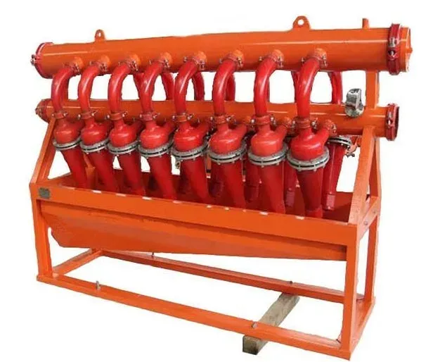 Desanders and Desilters
Desanders use larger cones (typically 6-12”) to remove sand-sized particles in the 40-75 micron range. Desilters use smaller, more numerous cones (4-5”) to pull out silt down to about 15-20 microns. Both work on centrifugal force: mud is pumped tangentially into the cone, solids spiral to the underflow, and clean mud exits the overflow. Keeping fine solids out of the mud reduces abrasive wear on pumps, valves, and the drill string, and maintains proper mud rheology.
Mud Mixers and Reclamation Systems
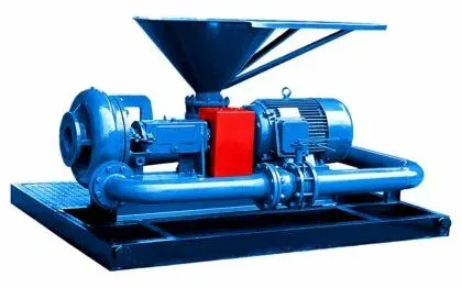 Mud Mixers
Mud mixers (hopper/venturi type and mechanical agitators) blend base fluid with barite, bentonite, polymers, and other additives to build and maintain mud properties. Reclamation systems (centrifuges, in particular) recover expensive liquid phase from drilled solids, returning clean mud to the active system. On a well using oil-based mud at $80-150/bbl, a good centrifuge pays for itself many times over.
Degassers
When formation gas enters the mud (H2S, CO2, methane), it reduces the mud’s effective density and can create explosive conditions at surface. Degassers strip these gases out.
 Degassers
Vacuum degassers draw mud into a low-pressure vessel where gas breaks out of solution; atmospheric degassers cascade mud over baffles to release gas. Either way, the gas is vented to the flare line. Gas-cut mud that is not degassed gives false readings on the mud balance and reduces hydrostatic head in the well, a dangerous combination.
Mud Cleaners
Combines the use of hydrocyclones and fine mesh shaker screens to remove fine drilled solids while retaining the valuable drilling fluid.
Types of Drilling Fluids
| Fluid Type | Base | Advantages | Limitations |
|---|---|---|---|
| Water-based Mud (WBM) | Water mixed with clays and chemicals | Most common; easy to use and dispose of | Can swell certain clay formations |
| Oil-based Mud (OBM) | Oil | Stable at high temperatures; less reactive with formations | More complex drilling situations; environmental concerns |
| Synthetic-based Mud (SBM) | Synthetic oils | Better environmental properties than OBM; maintains OBM benefits | Higher cost |
| Gaseous Fluids | Air, mist, foam, or nitrogen | Suited for specific situations where conventional mud is not suitable | Limited applications |
Fluid selection depends on formation chemistry, temperature, environmental regulations, and cost. WBM is the default unless conditions demand OBM (reactive shales, high temperatures, or tight tolerances in directional wells). SBM offers OBM performance with a lower environmental footprint, but at a premium price.
Blowout Preventer (BOP) System
The BOP stack sits on the wellhead and can shut in the well within seconds if formation pressure overwhelms the mud weight. A typical stack includes:
- Annular BOP: a rubber element that can close around any pipe size, kelly, or even open hole. Versatile but lower pressure rating than rams.
- Ram BOPs: pipe rams (seal around a specific pipe size), blind/shear rams (cut the pipe and seal the well completely), and variable-bore rams (seal around a range of pipe sizes).
BOPs are operated remotely from the driller’s panel and backed by an accumulator unit that stores pressurized hydraulic fluid for rapid closure. Post-Macondo, the regulatory focus on BOP testing, maintenance, and real-time monitoring has intensified significantly. If there is one piece of equipment on the rig you never want to fail, this is it.
Learn more about Blow-out preventer Systems (BOP) in this dedicated article.
Power Supply
A drilling rig is a self-contained power plant. Everything (top drive, mud pumps, drawworks, lighting, HVAC, BOP controls) runs off the rig’s own generators.
Power System Components
| Component | Role |
|---|---|
| Diesel/gas engine-generators | Primary power; typically 3-4 units producing 1,000-2,000 hp each |
| SCR (Silicon Controlled Rectifier) | Converts AC to DC for variable-speed motor control on older rigs |
| VFDs (Variable Frequency Drives) | AC-to-AC speed control on modern rigs; more efficient than SCR |
| Transformers | Step voltage up/down for different equipment loads |
| Switchgear & distribution panels | Route power, protect circuits, allow isolation for maintenance |
| UPS (Uninterruptible Power Supply) | Keeps safety-critical systems (BOP controls, fire/gas detection) running through power transients |
Offshore and remote land rigs have no grid backup, so redundancy is built in. Losing all power on a rig is one of the most dangerous scenarios because you lose mud circulation, BOP control, and lighting simultaneously. That is why rigs carry more generator capacity than the peak load requires.
Hoisting System
The hoisting system lifts, lowers, and suspends the drill string, casing, and tools in the wellbore. On a deep well, the hook load can exceed 1,000,000 lbs, and this system must handle that reliably, thousands of times per well.
Components of the Hoisting System
The derrick/mast was covered above. The remaining components form a block-and-tackle system:
Drawworks
The drawworks is the large winch on the rig floor that spools the drilling line to raise and lower the traveling block. It is the muscle of the hoisting system.
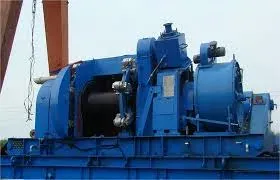 Drawworks
Modern drawworks use AC motors with disc brakes and automatic drilling controls. The driller controls hoist speed and can set the drawworks to maintain constant WOB while drilling ahead, a feature that improves ROP consistency and protects the bit.
Crown Block and Traveling Block
The crown block (fixed, top of mast) and traveling block (moves up/down) form the sheave system. The drilling line is reeved between them multiple times (typically 8 to 12 lines) to multiply the drawworks’ pulling force.
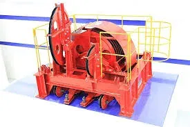 Crown Block
The hook hangs from the traveling block and supports the swivel (or top drive), which connects to the drill string. The swivel allows the string to rotate while providing a sealed passage for mud flow.
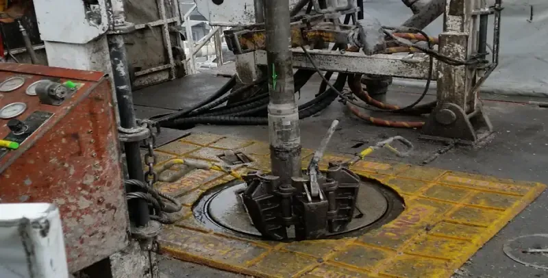
Rotary System
The rotary system turns the drill string and bit. On a traditional rig, the rotary table drives the kelly (square or hex pipe) via the master bushing and kelly bushing. On a modern rig, the top drive replaces the kelly entirely; these components were detailed earlier.
The rotary system controls two critical drilling parameters: RPM (rotational speed) and torque. Too much RPM in hard rock destroys the bit; too little in soft formations reduces ROP. The driller balances these against WOB and mud flow rate to optimize drilling performance. In directional wells, downhole mud motors and rotary steerable systems supplement (or replace) surface rotation, giving the directional driller finer control over the wellpath.
Well Control Equipment
Well control equipment keeps formation fluids from reaching the surface uncontrolled. The BOP system (covered above) is the centerpiece, but several other components work alongside it:
Choke Manifold
An assembly of high-pressure valves and adjustable chokes downstream of the BOP. During a kick, the driller routes returns through the choke manifold to control backpressure while circulating the influx out. This is the hands-on tool for executing the Driller’s Method or Wait and Weight kill procedure.
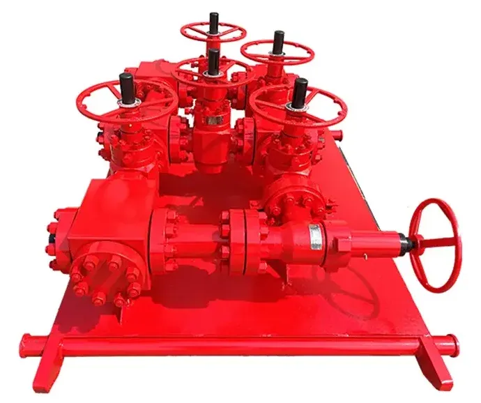 Choke Manifold
Kill Line
A high-pressure line connected to the BOP stack, used to pump heavy kill-weight mud into the well to regain hydrostatic control. The kill line and choke line work as a pair: mud goes in through the kill line, and formation fluid comes out through the choke line under controlled backpressure.
Accumulator Unit
Stores pressurized hydraulic fluid (typically 3,000 psi) to operate the BOP stack. The accumulator must have enough stored volume to close all BOPs and still maintain pressure without running the charging pumps. That is the regulatory minimum, and any well-run rig keeps more capacity than the minimum.
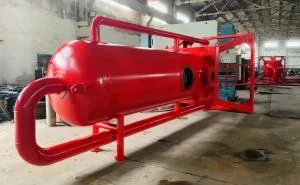
Mud-Gas Separator (Gas Buster)
A vertical vessel that separates gas from mud during a well control event. Mud enters near the top, gas breaks out and vents to the flare, and degassed mud flows from the bottom back to the pit system. When a large kick brings significant gas volumes to surface, the gas buster is the piece of equipment standing between you and an uncontrolled gas release at the rig floor.
Digital Innovations in Drilling Operations
The drilling industry has moved from analog gauges and gut feel to data-driven operations. The technologies that matter most today:
| Technology | What It Does in Practice |
|---|---|
| Real-time data analytics | Algorithms process WOB, torque, RPM, and mud data to optimize ROP and flag drilling dysfunctions (stick-slip, whirl) as they happen |
| Predictive maintenance | Vibration, temperature, and cycle-count data from pumps, drawworks, and top drives feed ML models that predict failures before they cause NPT |
| Digital twins | Virtual rig models simulate scenarios (e.g., “what happens if we increase mud weight by 0.5 ppg?”) before changes go live |
| Remote operations centers | One team of experts monitors 5-10 rigs simultaneously from an office, intervening in real time via satellite link |
| Drilling optimization software | Automates parameter adjustment (WOB, RPM, flow rate) to stay in the optimal drilling window; some systems now run closed-loop |
| Geosteering | Real-time LWD data guides the bit within the target zone; particularly valuable in thin horizontal pay zones |
 Blockchain technology
Internet of Things (IoT)
IoT ties all of this together. Sensors on every piece of major equipment (pumps, motors, BOPs, shale shakers) stream data to cloud platforms where it is aggregated, analyzed, and acted on.
 Internet of Things IoT
The practical results: fewer unplanned trips to change worn equipment, tighter well control through continuous pit-volume monitoring, faster leak detection via methane sensors, and better logistics through real-time equipment tracking. The rigs that have embraced these technologies consistently drill faster, cheaper, and safer than those that have not.
Leave a Comment
Have a question or feedback? Send us a message.
Previous Comments
Useful submit! I really want this sort of article.. that is very beneficial for me.