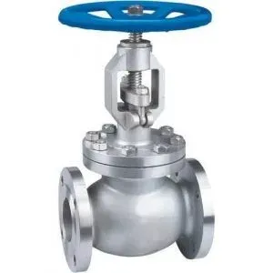
Globe Valve: Types & BS 1873 Specs
Globe Valve
What Is a Globe Valve?
Definition: A globe valve is a linear-motion valve used primarily for throttling and regulating flow. Its disc moves perpendicular to the seat, allowing precise flow control at the cost of a higher pressure drop compared to gate or ball valves.
A globe valve regulates flow in a pipeline by moving a disc against a stationary ring seat inside a generally spherical body. The name “globe” comes from that body shape, though modern designs often depart from a true sphere. You can throttle, start, or stop flow by positioning the disc relative to the seat; the gap between them sets how much fluid passes through.
 globe valve
Globe valves are bi-directional (unlike check valves), so flow can run either way. That said, for pure isolation duty, ball valves or gate valves are always the better choice. Globe valves earn their keep on throttling service.
The operation is simple: turning the handwheel (or actuator) moves the stem and disc toward or away from the seat. Move the disc down to restrict or shut off flow; raise it to open the path. This perpendicular disc travel is what gives globe valves their fine throttling control.
Typical applications include steam control in power plants and refineries, condensate and cooling water regulation, fuel oil systems, and manual bypass around control valves. If you need to hold a flow rate at a set point with a handwheel, a globe valve is the right tool.
Globe Valve Selection
Selecting a globe valve comes down to a few practical decisions:
| Factor | What to Determine |
|---|---|
| Fluid & service | Liquid vs. gas, corrosive or clean, toxic or benign. Drives body and trim material selection |
| Pressure & temperature | Must fall within the valve’s P-T rating per ASME B16.34 |
| Flow coefficient (Cv) | Calculate the required Cv from flow rate, density, and allowable pressure drop, then match to a valve size. Oversizing is a common mistake that kills controllability |
| End connections | Flanged (ASME B16.5), butt-weld, socket-weld, or threaded (dictated by line size and pressure class) |
| Body material | Carbon steel (WCB/A105) for general service; stainless (CF8M/F316) for corrosive media; alloy (WC6/F11) for high-temperature |
| Trim material | May differ from body material; select for erosion, corrosion, and leakage class requirements |
| Actuation | Handwheel for manual throttling; gear operator for large sizes; pneumatic/electric actuators for remote or automated operation. Size the actuator for max differential pressure |
For toxic or hazardous fluids, specify a bellows seal to eliminate stem leakage. In high-flow conditions, cage-guided trim reduces plug vibration and wear.
Advantages and Disadvantages
Globe valves do one thing extremely well (throttle flow) but that capability comes with trade-offs.
| Advantages | Disadvantages |
|---|---|
| Best-in-class throttling and flow regulation | Highest pressure drop of any common valve type (5-10x a gate valve) |
| Good seat tightness when closed | Heavier and bulkier than ball valves at the same size/class |
| Available in Z-body, Y-body, and angle patterns | Higher operating torque, especially at high pressure |
| Easy in-line maintenance (bonnet access to internals) | More expensive than gate or ball valves in larger sizes |
| Bi-directional flow capability | Not suitable for slurry or high-solids service; the tortuous flow path traps debris |
Bottom line: if you need flow regulation, use a globe valve. If pressure drop matters more than throttling, reach for a gate or ball valve instead.
 Globe valve disadvantage: pressure drop
Main Parts of Globe Valves
| Part | Function |
|---|---|
| Body | Main pressure-containing shell; houses all internals. Spherical or modified shape in cast iron, carbon steel, stainless steel, or alloy |
| Bonnet | Bolted, screwed, or welded closure on top of the body; provides access to internals and contains stem packing |
| Seat | Sealing surface the disc presses against when closed. Can be integral to the body or a replaceable ring. Replaceable seats are strongly preferred for maintenance |
| Disc (plug) | Moves perpendicular to flow to throttle or shut off. Shapes include flat disc, plug, and needle profiles, each with different Cv characteristics |
| Stem | Transmits handwheel or actuator motion to the disc. Rising stems (most common) give visual position indication; non-rising stems save headroom |
| Actuator | Handwheel for manual operation; gear operator for larger sizes; pneumatic, electric, or hydraulic actuators for remote/automated control |
| Packing | Flexible seal (PTFE or graphite) around the stem preventing external leakage. Graphite packing handles higher temperatures; PTFE gives lower friction |
| Gland & gland flange | Compresses the packing around the stem. Adjustable; tighten periodically as packing wears, but do not overtighten or you’ll score the stem |
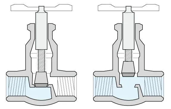
The image below shows the flow path through a globe valve: the disc lifts away from the seat, and the gap between them sets the flow rate. Note the two changes in flow direction: that is why globe valves have a higher pressure drop than straight-through designs.
Key Specifications (BS, API, ASME)
The two standards you will encounter most often for globe valves are BS 1873 (cast steel, NPS 2 and up) and API 602 (forged steel, NPS 4 and below). Beyond those, the following standards govern design, dimensions, and testing:
| Standard | Scope |
|---|---|
| BS 1873 | Cast steel globe and globe stop-check valves for petroleum and petrochemical service. Covers design, materials, P-T ratings, and testing |
| BS 5160 | Steel globe, check, and gate valves for general-purpose service |
| API 602 | Compact forged steel globe valves (also gate and check) for small-bore, high-pressure applications in oil & gas |
| API 598 | Valve inspection and testing requirements: hydrostatic shell, seat, and backseat tests |
| API 600 | Cast steel gate valves (flanged/BW), referenced here because its quality benchmarks are often applied to cast globe valves as well |
| ASME B16.34 | Master standard for valve materials, design, and P-T ratings across all valve types |
| ASME B16.10 | Face-to-face and end-to-end dimensions, critical for valve interchangeability in piping layouts |
| ASME B16.5 | Flanged connection dimensions and ratings for flanged globe valves |
Globe Valve Types
The body pattern determines the flow path, pressure drop, and where a globe valve fits best. In practice, you will spec three patterns 95% of the time: Z-body, Y-body, and angle.

Z-Body (T-Pattern) Globe Valve
The workhorse. A Z-shaped internal partition forces the fluid through two 90-degree turns. The stem sits perpendicular to the pipe. This gives the best throttling control but also the highest pressure drop of any globe valve pattern. Simple to maintain, widely stocked, and the default choice for most process throttling duties.
Y-Body Globe Valve (“Wye” Type)
The stem and seat angle at roughly 45 degrees to the pipe axis, creating a straighter flow path and significantly lower pressure drop than the Z-body. This is the go-to pattern for high-pressure steam and drain lines, anywhere pressure drop or erosion at the seat is a concern.
Angle Globe Valve
The body turns flow 90 degrees, combining the function of a globe valve and a pipe elbow. Flow changes direction only once (vs. twice in a Z-body), so pressure drop is lower. Use angle globe valves where the piping layout already requires a direction change. You save a fitting and reduce turbulence.
Oblique Pattern Globe Valve
Less common. Inlet and outlet ports are oriented diagonally, giving a more direct flow path than the Z-body but without the full 45-degree advantage of a Y-body. You will see these in European specifications occasionally; availability is limited compared to the three patterns above.
 Globe valves dimensions
The globe valve symbol in P&ID diagrams is the following:
Globe valves dimensions
The globe valve symbol in P&ID diagrams is the following: 
Globe Valve Materials (Cast/Forged)
Globe valve bodies are either cast or forged. The dividing line in practice is simple: forged bodies below 2 inches, cast bodies above 2 inches. Forged steel has a tighter grain structure, higher strength, and fewer defects, so for high-pressure small-bore service, forged is the default even when cast would technically work.
Common Body Materials
| Type | ASTM Spec | Typical Service |
|---|---|---|
| Cast carbon steel | A216 WCB | General service, moderate P-T |
| Cast stainless steel | A351 CF8M | Corrosive media, low-temperature |
| Cast alloy steel | A217 WC6 | High-temperature (up to ~600 degC) |
| Forged carbon steel | A105 | General service, small-bore high-pressure |
| Forged stainless steel | A182 F316 | Corrosive environments, small-bore |
| Forged alloy steel | A182 F11 | High-temperature small-bore |
Cast bodies accommodate complex internal geometries and large sizes cost-effectively, but they carry the risk of porosity, shrinkage cavities, and inclusions. Forged bodies are stronger and more uniform, but the forging process limits shape complexity and drives up cost for larger sizes.
| Factor | Cast | Forged |
|---|---|---|
| Typical size range | NPS 2 and up (BS 1873) | NPS 4 and below (API 602/BS 5352) |
| Strength & toughness | Good | Superior (aligned grain structure) |
| Defect risk | Higher (porosity, inclusions) | Low |
| Cost at large sizes | Lower | Significantly higher |
| Shape flexibility | High | Limited |
Globe Valve vs. Other Valve Types
The question I get asked most often: “When do I actually need a globe valve instead of a gate, ball, or butterfly?” The answer almost always comes down to whether you need to throttle flow or just isolate it.
| Feature | Globe Valve | Gate Valve | Ball Valve | Butterfly Valve | Plug Valve |
|---|---|---|---|---|---|
| Primary function | Throttling / flow regulation | On/off isolation | On/off isolation (some throttling) | On/off + moderate throttling | On/off + quick isolation |
| Pressure drop (fully open) | High (tortuous path) | Very low (straight-through) | Very low (full bore) | Low | Low |
| Throttling ability | Excellent | Poor (damages seats) | Limited (except V-port) | Moderate | Moderate |
| Operation | Multi-turn (slow) | Multi-turn (slow) | Quarter-turn (fast) | Quarter-turn (fast) | Quarter-turn (fast) |
| Sealing | Good disc-to-seat contact | Wedge-to-seat (good) | Excellent (soft-seated) | Adequate (degrades over time) | Good initially, wears faster |
| Relative size/weight | Large, heavy | Large, heavy | Compact, light | Very compact, light | Compact |
| Relative cost | Higher | Moderate | Moderate | Lowest at large sizes | Moderate |
| Slurry/solids tolerance | Poor | Fair | Fair (full bore) | Fair | Good |
Globe vs. gate: Use globe valves for throttling; use gate valves for isolation. Never throttle with a gate valve; the partially open wedge vibrates and chews up the seats within weeks. Conversely, do not use globe valves as block valves on large mains where pressure drop matters.
 Globe valve
Globe vs. ball: Ball valves win on speed, compactness, and pressure drop. Globe valves win on throttling precision. In practice, ball valves handle most isolation duties, and globe valves handle throttling and bypass service. Do not use standard ball valves for throttling; the soft seats erode at partially open positions. V-port or characterized ball valves are an exception.
Globe vs. butterfly: Butterfly valves are far cheaper and lighter at large diameters (NPS 8+), with lower pressure drop. But they cannot match a globe valve’s throttling precision, and their sealing degrades over time in high-pressure service. Use butterflies for large-diameter moderate-duty applications; use globe valves where precise regulation matters.
Globe vs. plug: Plug valves handle fluids with suspended solids better than globe valves (straight-through path vs. tortuous). They also open and close faster. But for precise flow regulation on clean fluids, the globe valve is superior.
Globe Valve GA Diagram
GA stands for “General Assembly” drawing. The image shows a typical flanged globe valve cross-section:
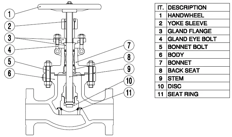 Globe valve general assembly drawing
Actual configurations vary widely depending on:
- body material: cast (BS 1873) vs. forged (API 602/BS 5352)
- bonnet design: standard bolted or pressure seal (Class 600+)
- end connections: flanged, butt-weld, socket-weld, or threaded
- disc type, stem type (rising/non-rising), seal type (conical or flat)
- specification: BS, API, or EN
- actuation: manual handwheel, gearbox, or actuator
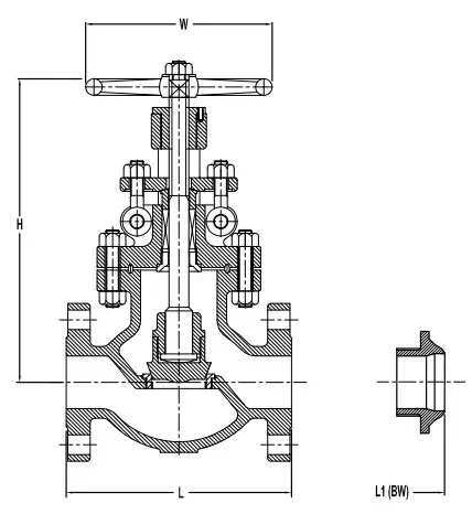
Globe Valve Dimensions (BS 1873)
The tables below show face-to-face length (L), open height (H), and handwheel diameter (W) for BS 1873 cast steel globe valves, bolted bonnet type.
Class 150
Dimensions in inches (millimeters)
| Sizes | L / L1 | H (Open) | W |
|---|---|---|---|
| 2″ | 8 (203) | 13-3/8 (340) | 8-7/8 (225) |
| 2-1/2″ | 8-1/2 (216) | 14-1/2 (368) | 8-7/8 (225) |
| 3″ | 9-1/2 (241) | 16-1/2 (419) | 11-7/8 (302) |
| 4″ | 11-1/2 (292) | 17-3/8 (441) | 12-3/4 (325) |
| 5″ | 14 (356) | 24 (610) | 12-3/4 (325) |
| 6″ | 16 (406) | 24 (610) | 17-3/4 (451) |
| 8″ | 19-1/2 (495) | 26-3/4 (679) | 21-5/8 (549) |
| 10″ | 24-1/2 (622) | 30 (762) | 30 (762) |
| 12″ | 27-1/2 (699) | 33-7/8 (860) | 30 (762) |
| 14″ | 31 (787) | 56 (1422) | 31-1/2 (800) |
| 16″ | 36 (914) | 64 (1626) | 35-1/2 (902) |
| GEAR OPERATOR RECOMMENDED FOR SIZE 10″ AND ABOVE |
Class 300
Dimensions in inches (millimeters)
| Sizes | L / L1 | H (Open) | W |
|---|---|---|---|
| 2″ | 10-1/2 (267) | 13-3/8 (340) | 9 (229) |
| 2-1/2″ | 11-1/2 (292) | 15-3/8 (390) | 9 (229) |
| 3″ | 12-1/2 (318) | 16-1/2 (419) | 13 (330) |
| 4″ | 14 (356) | 19-3/8 (492) | 14 (356) |
| 5″ | 15-3/4 (400) | 21-1/2 (546) | 15-3/4 (400) |
| 6″ | 17-1/2 (445) | 24-3/8 (619) | 17-3/4 (451) |
| 8″ | 22 (559) | 31-1/4 (794) | 22 (559) |
| 10″ | 24-1/2 (622) | 45 (1143) | 34 (864) |
| 12″ | 28 (711) | 49 (1245) | 34 (864) |
| GEAR OPERATOR RECOMMENDED FOR SIZE 8″ AND ABOVE |
Class 600
Dimensions in inches (millimeters)
| Sizes | L / L1 | H (Open) | W |
|---|---|---|---|
| 2″ | 11-1/2 (292) | 15-1/2 (394) | 9-1/2 (241) |
| 2-1/2″ | 13 (330) | 17 (432) | 11 (279) |
| 3″ | 14 (356) | 19 (483) | 13 (330) |
| 4″ | 17 (432) | 21 (533) | 14 (356) |
| 5″ | 20 (508) | 25 (635) | 15-3/4 (400) |
| 6″ | 22 (559) | 26-7/8 (683) | 18 (457) |
| 8″ | 26 (660) | 35 (889) | 20 (508) |
| 10″ | 31 (787) | 49 (1245) | 24 (610) |
| 12″ | 33 (838) | 58 (1473) | 30 (762) |
| GEAR OPERATOR RECOMMENDED FOR SIZE 8″ AND ABOVE |
Class 900
Dimensions in inches (millimeters)
| Sizes | L / L1 | H (Open) | W |
|---|---|---|---|
| 2″ | 14-1/2 (368) | 20-1/2 (521) | 12 (305) |
| 3″ | 15 (381) | 22-3/4 (578) | 14 (356) |
| 4″ | 18 (457) | 26-1/2 (673) | 21-1/2 (546) |
| 6″ | 24 (610) | 36 (914) | 20 (508) |
| 8″ | 29 (737) | 37 (940) | 24 (610) |
| GEAR OPERATOR RECOMMENDED FOR SIZE 6″ AND ABOVE |
Class 1500
Dimensions in inches (millimeters)
| Sizes | L / L1 | H (Open) | W |
|---|---|---|---|
| 2″ | 14-1/2 (368) | 24 (610) | 14 (356) |
| 3″ | 18-1/2 (470) | 26 (660) | 16 (406) |
| 4″ | 21-1/2 (546) | 28 (711) | 18 (457) |
| 6″ | 27-3/4 (705) | 37-1/2 (952) | 24 (610) |
| 8″ | 32-3/4 (832) | 45 (1143) | 24 (610) |
| GEAR OPERATOR RECOMMENDED FOR SIZE 6″ AND ABOVE |
Class 2500
Dimensions in inches (millimeters)
| Sizes | L / L1 | H (Open) | W |
|---|---|---|---|
| 2″ | 17-3/4 (451) | 25-1/2 (648) | 16 (406) |
| 3″ | 22-3/4 (578) | 32-1/2 (825) | 20 (508) |
| 4″ | 26-1/2 (673) | 47 (1194) | 24 (610) |
| 6″ | 36 (914) | 70-1/2 (1790) | 28 (711) |
| 8″ | 40-1/4 (1022) | / | / |
| GEAR OPERATOR RECOMMENDED FOR SIZE 6″ AND ABOVE |
Frequently Asked Questions
Why do globe valves have higher pressure drop than gate valves?
The flow path inside a globe valve makes two 90-degree turns (entering the seat area and exiting), creating significantly more resistance than a gate valve's straight-through design. This tortuous path is what allows globe valves to regulate flow effectively, but it results in a pressure drop 5-10 times higher than a gate valve of the same size. For systems where pressure loss is critical, use gate or ball valves for isolation instead.
What is the difference between T-pattern, Y-pattern, and angle-pattern globe valves?
A T-pattern (standard) globe valve has the stem perpendicular to the pipe (highest pressure drop but best throttling control. A Y-pattern globe valve has the stem at 45° to the pipe axis, providing a straighter flow path and lower pressure drop) ideal for high-pressure steam and drain lines. An angle-pattern globe valve turns the flow 90° ; it combines the function of a valve and an elbow, reducing piping and pressure drop in certain layouts.
When should I use a globe valve instead of a control valve?
Use a globe valve (with manual handwheel) for manual throttling, startup/shutdown flow control, and bypass around control valves. Use a dedicated control valve (with actuator and positioner) when precise, automated flow regulation is required based on instrument signals. In many process plants, globe valves serve as manual bypass valves around automatic control valves, allowing operators to maintain flow during control valve maintenance.
What is the difference between BS 1873 and API 602 globe valves?
BS 1873 covers cast steel globe valves in sizes NPS 2 and larger with flanged or butt-welded ends (used for process plants and refineries. API 602 covers compact forged steel globe valves in sizes NPS 4 and smaller with threaded, socket-weld, or flanged connections) used for small-bore, high-pressure applications like instrument isolation, drain, and vent service.
Leave a Comment
Have a question or feedback? Send us a message.