OCTG Pipes: API 5CT Casing & Tubing Guide
Types of OCTG Pipe
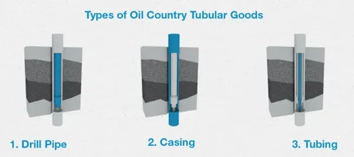
OCTG (Oil Country Tubular Goods) are pipes used for oil and gas extraction. Three main types:
| OCTG Type | Function | Size Range | Key Stresses |
|---|---|---|---|
| Casing | Stabilize wellbore, contain pressures | 4½” - 20” | Axial tension, internal/external pressure |
| Tubing | Transport hydrocarbons to surface | 1.050” - 5½” | Internal pressure, tensile loads |
| Drill Pipe | Rotate bit, circulate mud | Various | Torque, axial tension, internal pressure, bending |
Casing pipes stabilize the wellbore and are subject to axial tensions, internal pressures from produced fluids, and external pressures from surrounding formations.
Tubing pipes transport oil or gas from wellbore to surface. Segments are ~30’ long with threaded connections (standard or premium gas-tight).
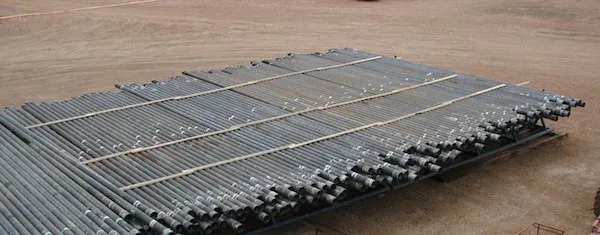
Drill pipes are heavyweight seamless tubular that rotate the drill bit and circulate drilling fluid. Subject to high torque, axial tension, internal pressure, and alternating bending loads in directional drilling.
 OCTG pipes: casing tubing drill typesThe API 5CT specification covers seamless and welded casing and tubing pipes for upstream operations (pipes that belong to the OCTG family, as illustrated above).
Key Takeaway: OCTG pipes are classified into three types; casing (wellbore stabilization, 4.5”-20”), tubing (hydrocarbon transport, 1.050”-5.5”), and drill pipes (bit rotation and mud circulation). Material selection per API 5CT ranges from H40 for shallow wells to Q125 for ultra-deep, high-pressure service, with sour service grades (L80, C90, T95) requiring controlled hardness and premium gas-tight connections.
Each type of OCTG pipe is reviewed in detail below.
OCTG “Casing” Pipes
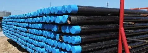
OCTG casing pipes are steel tubulars used in oil and gas wells for drilling, completion, and production. They line the wellbore to provide structural support and isolate formations. Below is a summary of their construction, grades, and application.
Function and Importance
Core functions of casing pipes:
| Function | Purpose |
|---|---|
| Structural support | Prevent wellbore collapse under formation pressure |
| Isolation | Seal off wellbore from surrounding formations, prevent fluid migration |
| Equipment mounting | Support for BOP, wellhead equipment, tubing, and packers |
| Pressure control | Maintain wellbore pressures during drilling, production, and workover |
Casing also protects the wellbore from:
- Water sand contamination
- Water intrusion into producing formations
2. Construction and Materials
- OCTG casing pipes are made of high-strength, corrosion-resistant steel alloys such as carbon steel, alloy steel, or stainless steel.
- They are manufactured by seamless extrusion or electric resistance welding (ERW) to achieve uniform strength and dimensional accuracy.
- Casing pipes are available in various sizes, grades, and specifications to match different well conditions, depths, and environments.
Types of OCTG Casing Pipes
| Casing Type | Description | Typical Application |
|---|---|---|
| Conventional | Standard casing, 4.5” - 20” diameter | Standard onshore wells |
| Premium | Enhanced corrosion/collapse resistance, improved connections | Deepwater, HPHT wells |
| Threaded & Coupled | Easy installation/removal, secure seal | All well types |
Grades and Specifications
API 5CT grades are classified by yield strength and service conditions:
| Grade | Min. Yield (psi) | Typical Use |
|---|---|---|
| H40 | 40,000 | Shallow wells, low stress |
| J55 | 55,000 | General purpose |
| K55 | 55,000 | Similar to J55, different chemistry |
| N80 | 80,000 | Deeper wells, higher collapse resistance |
| L80 | 80,000 | Sour service (H2S), controlled hardness |
| C90 | 90,000 | Sour service, higher strength |
| T95 | 95,000 | Sour service |
| P110 | 110,000 | Deep, high-pressure wells |
| Q125 | 125,000 | Ultra-deep, high-pressure |
Standards: API 5CT, ISO 11960.
5. Installation and Use
- Casing pipes are installed sequentially during drilling. Each section is lowered into the wellbore and connected to the previous section using threaded connections.
- Once installed, casing pipes are cemented in place to provide additional support and seal off the annular space between the casing and the surrounding formations.
- Casing pipes remain in place for the life of the well, acting as a permanent conduit for hydrocarbon extraction and maintaining structural integrity of the wellbore.
6. Challenges and Considerations
- Selecting the appropriate casing string requires evaluation of well depth, formation characteristics, reservoir pressure, temperature, and fluid properties.
- Operators must also comply with regulatory requirements and industry best practices for safe and environmentally responsible well construction and operation.
7. Sizes and End-Connections
Casing pipes are available in a diameter range 4 1/2 to 20 inches, and in the following materials: H-40, J-55, K-55, N-80, L-80/C, 90/T, 95, P110, Q-125 - as discussed in more detail below.
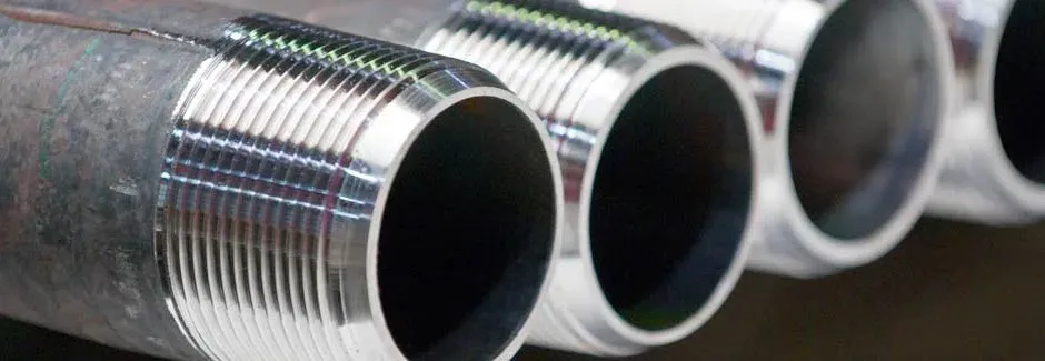
The main types of connections for casing pipes are STC (short threads), LTC (long threads), BTC (buttress threads), and premium gas-tight connections.
Casing pipes represent one of the largest individual cost items in well construction. Correct selection of casing size, materials, connectors, and setting depth directly affects both cost and well performance, making it a priority during the design phase.
Six types of casing strings:
| Casing String | Function | Typical Setting Depth |
|---|---|---|
| Conductor | Structural foundation, prevent surface erosion | 40-500 ft |
| Surface | Protect freshwater aquifers, BOP installation | 500-2,000 ft |
| Intermediate | Isolate troublesome formations, control pressures | 2,000-12,000 ft |
| Production | Final string, isolate pay zone | To TD (total depth) |
| Liner | Partial string from previous casing to TD | Lower section only |
| Liner Tieback | Extends liner to surface | Connects liner to wellhead |
All casing is cemented in place to provide structural support, seal the annulus, and prevent formation fluid migration.
The strict quality requirement for steel is due to the harsh working conditions of the casing.
The steel product should be produced and checked following special standards or specifications. ISO 11960 and API Spec 5CT have specified the steel product standards of the casing.
OCTG “Tubing” Pipes
OCTG tubing pipes are steel tubulars installed inside the casing string to transport oil, natural gas, and production fluids from the reservoir to the surface. They are a primary component of well completion and production systems.
1. Function and Importance
- Tubing pipes convey oil, natural gas, and production fluids from the reservoir to the surface during well production operations.
- They provide a pathway for hydrocarbon flow from the downhole reservoir to surface processing facilities.
- Tubing pipes also support and protect downhole equipment such as pumps, packers, and sensors.
Tubing pipes must resist high mechanical loads and deformations during production operations.
Tubing diameter must be properly sized for the expected flow rate. An undersized diameter reduces production rate and lowers the return on investment, while an oversized tubing adds unnecessary steel cost to the well construction without a corresponding benefit.
2. Construction and Materials
- OCTG tubing pipes are made of high-strength, corrosion-resistant steel alloys such as carbon steel, alloy steel, or stainless steel.
- They are manufactured by seamless extrusion or electric resistance welding (ERW) to achieve uniform strength and dimensional accuracy.
- Tubing pipes are available in various sizes, grades, and specifications to match different well conditions, depths, and environments.
3. Types of OCTG Tubing Pipes
- Conventional Tubing: Standard tubing pipes used in conventional oil and gas wells, typically ranging from 2.375 inches to 4.5 inches in diameter.
- Premium Tubing: High-performance tubing pipes with enhanced properties such as corrosion resistance, high collapse resistance, and improved connection designs. Premium tubing is often used in deepwater, high-pressure, and high-temperature wells.
- Coiled Tubing: Continuous lengths of small-diameter tubing wound onto a spool for use in well intervention and workover operations. Coiled tubing offers faster installation, reduced rig time, and improved access to deviated and horizontal wellbores.
4. Grades and Specifications
- OCTG tubing pipes are classified into grades based on their mechanical properties, chemical composition, and performance characteristics.
- Common tubing grades include API 5CT grades such as J55, K55, N80, L80, C90, T95, P110, and Q125, each designed for specific well conditions and operating requirements.
- Specifications are established by the American Petroleum Institute (API) and international standards organizations to ensure quality, consistency, and compatibility with well equipment and procedures.
5. Installation and Use
- Tubing pipes are installed inside the casing strings during well completion, forming a continuous conduit for production fluids from the reservoir to the surface.
- Once installed, tubing pipes are connected to downhole equipment such as pumps, packers, and safety valves to support production and monitoring.
- Tubing pipes remain in place for the life of the well, allowing continuous production and providing access for well intervention and maintenance.
6. Challenges and Considerations
- Selecting the appropriate tubing string requires evaluation of reservoir characteristics, production rates, fluid properties, and wellbore conditions.
- Operators must comply with regulatory requirements and industry best practices for safe and efficient well operation.
7. Sizes, Materials, End-Connections
Tubing pipes are manufactured in seamless and welded execution, in the size range of 1.050 to 5 1/2 inches (consult this article to see the AP5CT tubing pipes sizes) and in the following material grades: H-40, J-55, K-55, N-80, L-80, C-90, T-95, P-110, Q-125 (more details about API 5CT tubing materials are in this article).
The main types of connections for tubing pipes are NUE (non-upset), EUE (external upset), and premium. Corrosion resistance under sour service conditions is a very important OCTG characteristic, especially for casing and tubing.
OCTG “Drill” Pipes
 OCTG drill pipesOCTG drill pipes are tubular components that form the drilling string. They transmit drilling fluid to the bit, provide structural support to the drilling assembly, and transfer torque for bit rotation.
1. Function and Importance
- Drill pipes transmit drilling fluid from the surface to the drill bit at the bottom of the wellbore.
- They provide structural support to the drilling assembly and transfer rotation and axial load to the drill bit for formation penetration.
- Drill pipes also carry rock cuttings and debris from the wellbore to the surface, maintaining the drilling operation.
2. Construction and Materials
- OCTG drill pipes are made of high-strength alloyed steel to withstand drilling loads and harsh downhole conditions.
- They are manufactured by seamless extrusion or electric resistance welding (ERW) to achieve uniform strength and dimensional accuracy.
- Drill pipes are available in various sizes, lengths, and specifications to match different drilling environments, depths, and applications.
3. Design and Components
- Drill pipes consist of the pipe body, tool joints, and threads.
- The pipe body is the main cylindrical section, while the tool joints are the thicker, threaded ends that connect adjacent pipe sections.
- Tool joints are designed to withstand high loads, torque, and bending stresses. They are typically made of hardened steel for durability.
- Threads are machined onto the tool joints for connection and disconnection of drill pipe sections and attachment of other drilling tools.
4. Specifications and Grades
- OCTG drill pipes are classified into grades based on their mechanical properties, chemical composition, and performance characteristics.
- Common drill pipe grades include API 5DP grades such as E75, X95, G105, and S135, each suited to specific drilling conditions and formations.
- Specifications are established by the American Petroleum Institute (API) and international standards organizations to ensure quality, consistency, and compatibility with drilling equipment.
5. Installation and Use
- Drill pipes are assembled into a drilling string and lowered into the wellbore using a drilling rig.
- The drill pipes are connected end-to-end using threaded connections and are rotated and pushed downward to advance the drill bit into the formation.
- Drilling fluid (mud) is pumped through the drill pipes to cool the drill bit, carry rock cuttings to the surface, and provide hydraulic pressure to stabilize the wellbore.
6. Maintenance and Inspection
- Drill pipes undergo regular inspection and maintenance to verify their integrity and performance.
- Inspection methods include visual examination, dimensional checks, ultrasonic testing (UT), magnetic particle testing (MT), and other non-destructive testing (NDT) techniques to detect defects, cracks, and wear.
OCTG Pipe Manufacturing Process
The manufacturing process of OCTG pipes involves several stages to produce steel pipes that meet oil and gas industry requirements:
| Step | Process | Description |
|---|---|---|
| 1. Steel Making | BOF, EAF, or continuous casting | Production of steel from raw materials (iron ore, coal, alloying elements) |
| 2. Billet Production | Continuous casting or molds | Steel is cast into solid cylindrical billets as starting material |
| 3. Pipe Manufacturing | Forging, extrusion, or welding | Billets heated and formed into seamless pipes (rolling passes) or welded pipes (ERW, SAW) |
| 4. Heat Treatment | Annealing, normalizing, Q&T | Relieves internal stresses, refines grain structure, enhances strength and toughness |
| 5. Surface Finishing | Shot blasting, pickling, coating | Removes surface defects, improves corrosion resistance and appearance |
| 6. Testing & Inspection | UT, MT, RT, HYT, dimensional | Rigorous NDT and quality checks throughout manufacturing |
| 7. Marking & Identification | Stenciling | Size, grade, heat number, manufacturer ID for traceability |
| 8. Packaging & Shipping | Bundling, crating | Protected in bundles or wooden crates for transit |
Each stage follows stringent quality control measures and industry standards to produce OCTG pipes suitable for the demanding downhole environments of oil and gas wells.
Manufacturing process details for OCTG casing and tubing pipes:
- The continuous mandrel-rolling process and the push bench process are used for sizes between 21 and 178 mm OD.
- Plug mill rolling is used for sizes between 140 and 406 mm OD.
- Cross-roll piercing and Pilger rolling are used for sizes between 250 and 660 mm OD.
These processes typically do not allow the thermo-mechanical processing customary for the strip and plate products used for welded pipes.
Therefore, the high-strength seamless pipe must be produced by increasing the alloying content in combination with a suitable heat treatment such as quench & tempering.
Meeting the fundamental requirement of a fully martensitic microstructure even at large pipe wall thickness requires good hardenability. Chrome (Cr) and Manganese (Mn) are the main alloying elements used to produce good hardenability in conventional heat-treatable steel.
However, the requirement for good sulfide stress cracking (SSC) resistance limits their use. Mn tends to segregate during continuous casting and can form large MnS inclusions that reduce hydrogen-induced cracking (HIC) resistance. Higher levels of Cr can lead to the formation of Cr7C3 precipitates with coarse plate-shaped morphology, which acts as hydrogen collectors and crack initiators.
Alloying with Molybdenum can overcome the limitations of Mn and Cr alloying. Mo is a much stronger hardener than Mn and Cr, so it can easily recover the effect of a reduced amount of these elements.
Traditionally, OCTG grades were carbon-manganese steels (up to the 55-KSI strength level) or Mo-containing grades up to 0.4% Mo. In recent years, deep well drilling and reservoirs containing contaminants that cause corrosive attacks have created a strong demand for higher-strength materials resistant to hydrogen embrittlement and SCC.
Highly tempered martensite is the structure most resistant to SSC at higher strength levels, and 0.75% is the Mo concentration that produces the optimum combination of yield strength and to SSC resistance.
OCTG Pipe Selection Criteria
Selecting the appropriate OCTG pipes for a well affects the integrity, efficiency, and safety of drilling and production operations. The following factors should be evaluated:
1. Well Conditions and Environment
- Assess the geological and reservoir conditions: formation type, depth, pressure, temperature, and fluid properties.
- Account for downhole hazards such as corrosive fluids, high-pressure zones, sour gas (H2S), and high-temperature conditions, which influence material and coating selection.
2. Operating Requirements and Specifications:
- Determine the required casing size, wall thickness, grade, length, and connection type (API or premium connections).
- Select OCTG pipes that meet industry standards and regulatory requirements set by the American Petroleum Institute (API) and international standards organizations.
3. Pipe Grade and Material:
- Choose the OCTG pipe grade based on well conditions, operating parameters, and performance requirements.
- Evaluate mechanical properties (yield strength, tensile strength, hardness), corrosion resistance, collapse resistance, and fatigue resistance.
- Assess the suitability of carbon steel, alloy steel, or stainless steel for the specific downhole environment and service conditions.
4. Connection Type and Performance:
- Select pipe connections (threaded and coupled, integral premium connections) based on well design, completion method, and operational requirements.
- Evaluate connection performance: sealing integrity, tensile strength, torque capacity, and resistance to pressure and bending loads.
5. Premium vs. Conventional Pipes:
- Weigh the benefits and trade-offs of premium OCTG pipes against conventional pipes.
- Premium pipes offer improved corrosion resistance, higher collapse resistance, better connection designs, and extended service life, but at a higher cost.
6. Cost and Budget Considerations:
- Assess the total cost of each OCTG pipe option, including upfront procurement costs, lifecycle costs, and potential savings from improved performance and reliability.
- Balance pipe quality requirements against budget constraints and project economics to optimize value and minimize risk.
7. Supplier Reputation and Support:
- Choose reputable OCTG pipe manufacturers with a track record of delivering quality products, reliable service, and technical support.
- Evaluate manufacturing capabilities, quality assurance processes, supply chain reliability, and customer service responsiveness.
8. Regulatory Compliance and Certification:
- Confirm that OCTG pipes comply with applicable industry standards such as API 5CT for casing and tubing products.
- Verify the authenticity of product certifications, test reports, and compliance documentation to confirm product quality and traceability.
OCTG pipe selection requires systematic evaluation of well conditions, operating requirements, pipe properties, connection types, cost, supplier reliability, and regulatory compliance. Applying industry expertise and best practices during this process helps ensure the right pipes are specified for each application.
OCTG Pipe Manufacturers
The main manufacturers of OCTG pipes are listed below:
Tubos Reunidos (Spain)
Tubos Reunidos is a Spanish manufacturer specializing in seamless steel pipes, including OCTG products. They offer various casing and tubing solutions for the oil and gas sector.
Vallourec (France)
Despite its troubled situation in the last few years, Vallourec is a major player in the OCTG industry. The company manufactures and distributes drill, casing, and tubing pipes with premium connections.
Tenaris (Italy & Argentina)
Tenaris is based in Argentina and manufactures various mechanical, structural, process, and OCTG pipes. In the OCTG area, Tenaris supplies drilling, casing, and tubing pipes with standard and premium connections, and other tubular equipment for upstream operations (such as sucker rods and coil tubes). Tenaris produces OCTG pipes in most major API grades, including carbon, alloy, and higher grades. Besides being a mill, Tenaris is also involved in contracting and consulting in upstream, midstream, and downstream oil & gas.
US Steel Tubular Products (USA)
US Steel is a multinational steel company covering various industries, from food to oil and gas. The company has a significant position in the OCTG industry, producing drill, casing, and tubing pipes API 5CT in most sizes and API material grades with different types of commercial and proprietary connections.
Evraz North America (USA)
Evraz North America is a leading producer of OCTG pipes in North America, offering a variety of casing and tubing solutions for oil and gas applications.
Nippon Steel CORP. and Sumitomo (Japan)
Nippon Steel is an accredited supplier of OCTG pipes, used throughout the world and recognized for their exceptional quality. The company has been very active in developing stronger materials and innovative connections. Further, the company has a well-established distribution business, able to support exploration and upstream activities in real time.
JFE Steel Corporation (Japan)
JFE Steel Corporation is a Japanese steelmaker known for its high-performance steel products, including OCTG pipes. They offer a variety of casing and tubing solutions for the oil and gas industry.
TMK Group (Russia)
TMK is one of the top five pipe manufacturers in the world. Besides process pipes, TMK manufactures and distributes seamless and welded OCTG pipes in various material grades through a consolidated network of regional offices.
SeAH Steel Corporation (South Korea)
SeAH Steel Corporation is a South Korean manufacturer of steel pipes, including OCTG products. They supply casing, tubing, and line pipes to customers worldwide.
Arcelor Mittal (India)
Arcelor Mittal, a giant Indian/French steel conglomerate, is involved in the production and distribution of OCTG pipes for exploration and extraction operations.The Arcelor Mittal pipe and tubes division represents a small fraction of the whole company turnover (definitely less than 5%) but can still be considered one of the major players in the oil exploration and upstream industries.
Jindal Steel & Power Ltd. (India)
Jindal Steel & Power Ltd. is an Indian steel manufacturer producing OCTG pipes for the oil and gas sector. They offer a full range of casing and tubing products.
Borusan Mannesmann (Turkey)
Borusan Mannesmann is a Turkish manufacturer of welded steel pipes, including OCTG products. They provide casing, tubing, and line pipes for oil and gas exploration and production.
Chinese Manufacturers of OCTG Pipes
Several Chinese manufacturers produce OCTG pipes for both domestic and international markets:
| Manufacturer | Location | Products |
|---|---|---|
| Baosteel Group Corporation (Baowu Steel) | China | Casing, tubing, drill pipes |
| TPCO (Tianjin Pipe Corporation) | Tianjin | Seamless casing, tubing, line pipes |
| Hengyang Valin Steel Tube Co., Ltd. | Hengyang (Valin Group) | Seamless casing, tubing, drill pipes |
| Panyu Chu Kong Steel Pipe Co., Ltd. (PCK) | Guangzhou | Longitudinally welded casing, tubing, line pipes |
| Jiangsu Changbao Steel Tube Co., Ltd. | Jiangsu Province | Seamless casing, tubing, drill pipes |
| Jiangsu Yulong Steel Pipe Co., Ltd. | Jiangsu (Yulong Group) | Seamless casing, tubing, line pipes |
| Jiangsu Tiancheng Group Limited | Jiangsu Province | Seamless casing, tubing, line pipes |
| Zhejiang Zhongkuang Steel Pipe Co., Ltd. | Zhejiang Province | Seamless casing, tubing, drill pipes |
| Tianjin Dalipu Oil Country Tubular Goods | Tianjin | Casing, tubing, drill pipes |
| Shengli Oil & Gas Pipe Holdings Limited | Shandong Province | Casing, tubing, line pipes |
These Chinese manufacturers produce OCTG pipes that meet international standards and are significant suppliers of tubular products to the global oil and gas industry.
OCTG Pipe Dimensions
OCTG Casing Pipe Sizes
Note: P = plain end, S = short round thread, L = long round thread, B = buttress thread. Sizes per API 5CT specification Source: API - American Petroleum Institute
| NPS | Weight (lb/ft) | OD (in) | OD (mm) | Wall (in) | Wall (mm) | H-40 | J-55/K-55 | M-65 | L-80/C-95 | N-80 | C-90/T-95 | P-110 | Q-125 |
|---|---|---|---|---|---|---|---|---|---|---|---|---|---|
| 7 5/8” | 24.00 | 7.625 | 193.68 | 0.300 | 7.62 | PS | - | - | - | - | - | - | - |
| 7 5/8” | 26.40 | 7.625 | 193.68 | 0.328 | 8.33 | - | PSLB | PSLB | PLB | PLB | PLB | PLB | - |
| 7 5/8” | 29.70 | 7.625 | 193.68 | 0.375 | 9.53 | - | - | PLB | PLB | PLB | PLB | PLB | - |
| 7 5/8” | 33.70 | 7.625 | 193.68 | 0.430 | 10.92 | - | - | PLB | PLB | PLB | PLB | PLB | - |
| 7 5/8” | 39.00 | 7.625 | 193.68 | 0.500 | 12.70 | - | - | - | PLB | PLB | PLB | PLB | PLB |
| 7 5/8” | 42.80 | 7.625 | 193.68 | 0.562 | 14.27 | - | - | - | PLB | PLB | PLB | PLB | PLB |
| 7 5/8” | 45.30 | 7.625 | 193.68 | 0.595 | 15.11 | - | - | - | PLB | PLB | PLB | PLB | PLB |
| 7 5/8” | 47.10 | 7.625 | 193.68 | 0.625 | 15.88 | - | - | - | PLB | PLB | PLB | PLB | PLB |
| 7 5/8” | 51.20 | 7.625 | 193.68 | 0.687 | 17.45 | - | - | - | - | - | P | - | - |
| 7 5/8” | 55.30 | 7.625 | 193.68 | 0.750 | 19.05 | - | - | - | - | - | P | - | - |
| 7 3/4” | 46.10 | 7.750 | 196.85 | 0.595 | 15.11 | - | - | - | P | P | P | P | P |
| 8 5/8” | 24.00 | 8.625 | 219.08 | 0.264 | 6.71 | - | PS | PS | - | - | - | - | - |
| 8 5/8” | 28.00 | 8.625 | 219.08 | 0.304 | 7.72 | PS | - | PS | - | - | - | - | - |
| 8 5/8” | 32.00 | 8.625 | 219.08 | 0.352 | 8.94 | PS | PSLB | PSLB | - | - | - | - | - |
| 8 5/8” | 36.00 | 8.625 | 219.08 | 0.400 | 10.16 | - | PSLB | PSLB | PLB | PLB | PLB | PSLB | - |
| 8 5/8” | 40.00 | 8.625 | 219.08 | 0.450 | 11.43 | - | - | PLB | PLB | PLB | PLB | PLB | - |
| 8 5/8” | 44.00 | 8.625 | 219.08 | 0.500 | 12.70 | - | - | PLB | PLB | PLB | PLB | PLB | - |
| 8 5/8” | 49.00 | 8.625 | 219.08 | 0.557 | 14.15 | - | - | - | PLB | PLB | PLB | PLB | PLB |
| 9 5/8” | 32.30 | 9.625 | 244.48 | 0.312 | 7.92 | PS | - | - | - | - | - | - | - |
| 9 5/8” | 36.00 | 9.625 | 244.48 | 0.352 | 8.94 | PS | PSLB | PSLB | - | - | - | - | - |
| 9 5/8” | 40.00 | 9.625 | 244.48 | 0.395 | 10.03 | - | PSLB | PSLB | PLB | PLB | PLB | - | - |
| 9 5/8” | 43.50 | 9.625 | 244.48 | 0.435 | 11.05 | - | - | PLB | PLB | PLB | PLB | PLB | - |
| 9 5/8” | 47.00 | 9.625 | 244.48 | 0.472 | 11.99 | - | - | PLB | PLB | PLB | PLB | PLB | PLB |
| 9 5/8” | 53.50 | 9.625 | 244.48 | 0.545 | 13.84 | - | - | - | PLB | PLB | PLB | PLB | PLB |
| 9 5/8” | 58.40 | 9.625 | 244.48 | 0.595 | 15.11 | - | - | - | PLB | PLB | PLB | PLB | PLB |
| 9 5/8” | 59.40 | 9.625 | 244.48 | 0.609 | 15.47 | - | - | - | - | - | P | - | - |
| 9 5/8” | 64.90 | 9.625 | 244.48 | 0.672 | 17.07 | - | - | - | - | - | P | - | - |
| 9 5/8” | 70.30 | 9.625 | 244.48 | 0.734 | 18.64 | - | - | - | - | - | P | - | - |
| 9 5/8” | 75.60 | 9.625 | 244.48 | 0.797 | 20.24 | - | - | - | - | - | P | - | - |
| NPS | Weight (lb/ft) | OD (in) | OD (mm) | Wall (in) | Wall (mm) | H-40 | J-55/K-55 | M-65 | L-80/C-95 | N-80 | C-90/T-95 | P-110 | Q-125 |
|---|---|---|---|---|---|---|---|---|---|---|---|---|---|
| 10 3/4” | 32.75 | 10.75 | 273.05 | 0.279 | 7.09 | PS | - | - | - | - | - | - | - |
| 10 3/4” | 40.50 | 10.75 | 273.05 | 0.350 | 8.89 | PS | PSB | PSB | - | - | - | - | - |
| 10 3/4” | 45.50 | 10.75 | 273.05 | 0.400 | 10.16 | - | PSB | PSB | - | - | - | - | - |
| 10 3/4” | 51.00 | 10.75 | 273.05 | 0.450 | 11.43 | - | PSB | PSB | PSB | PSB | PSB | PSB | - |
| 10 3/4” | 55.50 | 10.75 | 273.05 | 0.495 | 12.57 | - | - | PSB | PSB | PSB | PSB | PSB | - |
| 10 3/4” | 60.70 | 10.75 | 273.05 | 0.545 | 13.84 | - | - | - | - | - | PSB | PSB | PSB |
| 10 3/4” | 65.70 | 10.75 | 273.05 | 0.595 | 15.11 | - | - | - | - | - | PSB | PSB | PSB |
| 10 3/4” | 73.20 | 10.75 | 273.05 | 0.672 | 17.07 | - | - | - | - | - | P | - | - |
| 10 3/4” | 79.20 | 10.75 | 273.05 | 0.734 | 18.64 | - | - | - | - | - | P | - | - |
| 10 3/4” | 85.30 | 10.75 | 273.05 | 0.797 | 20.24 | - | - | - | - | - | P | - | - |
| 11 3/4” | 42.00 | 11.75 | 298.45 | 0.333 | 8.46 | PS | - | - | - | - | - | - | - |
| 11 3/4” | 47.00 | 11.75 | 298.45 | 0.375 | 9.53 | - | PSB | PSB | - | - | - | - | - |
| 11 3/4” | 54.00 | 11.75 | 298.45 | 0.435 | 11.05 | - | PSB | PSB | - | - | - | - | - |
| 11 3/4” | 60.00 | 11.75 | 298.45 | 0.489 | 12.42 | - | PSB | PSB | PSB | PSB | PSB | PSB | PSB |
| 11 3/4” | 65.00 | 11.75 | 298.45 | 0.534 | 13.56 | - | - | - | P | P | P | P | P |
| 11 3/4” | 71.00 | 11.75 | 298.45 | 0.582 | 14.78 | - | - | - | P | P | P | P | P |
| 13 3/8” | 48.00 | 13.375 | 339.73 | 0.330 | 8.38 | PS | - | - | - | - | - | - | - |
| 13 3/8” | 54.50 | 13.375 | 339.73 | 0.380 | 9.65 | - | PSB | PSB | - | - | - | - | - |
| 13 3/8” | 61.00 | 13.375 | 339.73 | 0.430 | 10.92 | - | PSB | PSB | - | - | - | - | - |
| 13 3/8” | 68.00 | 13.375 | 339.73 | 0.480 | 12.19 | - | PSB | PSB | PSB | PSB | PSB | PSB | - |
| 13 3/8” | 72.00 | 13.375 | 339.73 | 0.514 | 13.06 | - | - | - | PSB | PSB | PSB | PSB | PSB |
P = plain end, S = short round thread, L = long round thread, B = buttress thread
OCTG Tubing Pipe Sizes
Note: P = plain end, N = Non-upset thread and coupling, U = upset thread and coupling. Sizes per API 5CT specification Source: API - American Petroleum Institute
| NPS | Weight Non-upset (lb/ft) | Weight Ex-upset (lb/ft) | OD (mm) | Wall (mm) | Nom Wt Non-upset | Nom Wt Ex-upset | J-55 | L-80 | N-80 | C-90 | T-95 | P-110 |
|---|---|---|---|---|---|---|---|---|---|---|---|---|
| 2 3/8” | 4 | - | 60.32 | 4.24 | 5.95 | - | PN | PN | PN | PN | PN | - |
| 2 3/8” | 4.6 | 4.7 | 60.32 | 4.83 | 6.85 | 6.99 | PNU | PNU | PNU | PNU | PNU | PNU |
| 2 3/8” | 5.8 | 5.95 | 60.32 | 6.45 | 8.63 | 8.85 | - | PNU | PNU | PNU | PNU | PNU |
| 2 3/8” | 6.6 | - | 60.32 | 7.49 | 9.82 | - | - | P | - | P | P | - |
| 2 3/8” | 7.35 | 7.45 | 60.32 | 8.53 | 10.94 | 11.09 | - | PU | - | PU | PU | - |
| 2 7/8” | 6.4 | 6.5 | 73.02 | 5.51 | 9.52 | 9.67 | PNU | PNU | PNU | PNU | PNU | PNU |
| 2 7/8” | 7.8 | 7.9 | 73.02 | 7.01 | 11.61 | 11.76 | - | PNU | PNU | PNU | PNU | PNU |
| 2 7/8” | 8.6 | 8.7 | 73.02 | 7.82 | 12.8 | 12.95 | - | PNU | PNU | PNU | PNU | PNU |
| 2 7/8” | 9.35 | 9.45 | 73.02 | 8.64 | 13.91 | 14.06 | - | PU | - | PU | PU | - |
| 2 7/8” | 10.5 | - | 73.02 | 9.96 | 15.63 | - | - | P | - | P | P | - |
| 2 7/8” | 11.5 | - | 73.02 | 11.18 | 17.11 | - | - | P | - | P | P | - |
| 3 1/2” | 7.7 | - | 88.9 | 5.49 | 11.46 | - | PN | PN | PN | PN | PN | - |
| 3 1/2” | 9.2 | 9.3 | 88.9 | 6.45 | 13.69 | 13.84 | PNU | PNU | PNU | PNU | PNU | PNU |
| 3 1/2” | 10.2 | - | 88.9 | 7.34 | 15.18 | - | PN | PN | PN | PN | PN | - |
| 3 1/2” | 12.7 | 12.95 | 88.9 | 9.52 | 18.9 | 19.27 | - | PNU | PNU | PNU | PNU | PNU |
| 3 1/2” | 14.3 | - | 88.9 | 10.92 | 21.28 | - | - | P | - | P | P | - |
| 3 1/2” | 15.5 | - | 88.9 | 12.09 | 23.07 | - | - | P | - | P | P | - |
| 3 1/2” | 17 | - | 88.9 | 13.46 | 25.3 | - | - | P | - | P | P | - |
| 4” | 9.5 | - | 101.6 | 5.74 | 14.14 | - | PN | PN | PN | PN | PN | PN |
| 4” | 10.7 | 11 | 101.6 | 6.65 | - | 16.37 | PU | PU | PU | PU | PU | PU |
| 4” | 13.2 | - | 101.6 | 8.38 | 19.64 | - | - | P | - | P | P | - |
| 4” | 16.1 | - | 101.6 | 10.54 | 23.96 | - | - | P | - | P | P | - |
| 4” | 18.9 | - | 101.6 | 12.7 | 28.13 | - | - | P | - | P | P | - |
| 4” | 22.2 | - | 101.6 | 15.49 | 33.04 | - | - | P | - | P | P | - |
| 4 1/2” | 12.6 | 12.75 | 114.3 | 6.88 | 18.75 | 18.97 | PNU | PNU | PNU | PNU | PNU | PNU |
| 4 1/2” | 15.2 | - | 114.3 | 8.56 | 22.62 | - | - | P | - | P | P | - |
| 4 1/2” | 17 | - | 114.3 | 9.65 | 25.3 | - | - | P | - | P | P | - |
| 4 1/2” | 18.9 | - | 114.3 | 10.92 | 28.13 | - | - | P | - | P | P | - |
| 4 1/2” | 21.5 | - | 114.3 | 12.7 | 32 | - | - | P | - | P | P | - |
| 4 1/2” | 23.7 | - | 114.3 | 14.22 | 35.27 | - | - | P | - | P | P | - |
| 4 1/2” | 26.1 | - | 114.3 | 16 | 38.84 | - | - | P | - | P | P | - |
P = plain end, N = non-upset thread and coupling, U = upset thread and coupling
API 5CT Tolerances for OCTG Pipes
| Tube Size (mm) | OD Tolerance | Wall Thickness Tolerance |
|---|---|---|
| < 114.3 | ±0.79 mm | -12.5% |
| ≥ 114.3 | -0.5%, +1% | -12.5% |
Materials for OCTG Pipes
The most common materials for OCTG pipes are API H40, J55, K55, L80, N80, P110, and Q125 (casing and tubing pipes). These API grades feature increasing mechanical properties (tensile and yield strength).
OCTG casing and tubing pipes are available in the following material grades:
API H40
API H40 grade is for general-purpose OCTG pipe material with the following mechanical properties:
Chemical Composition
| C | Mn | Mo | Cr | Ni | Cu | Ti | P | S | Si | V | Al | |
|---|---|---|---|---|---|---|---|---|---|---|---|---|
| Min | - | - | - | - | - | - | - | - | - | - | - | - |
| Max | - | - | - | - | - | - | - | 0.030 | 0.030 | - | - | - |
Mechanical Properties
| Min Tensile Strength | 414 MPa | 60,000 psi min |
|---|---|---|
| Min Yield Strength | 276 MPa | 552 MPa max |
| 40,000 psi | 80,000 psi max | |
| Total Elongation Under Load | 0.500 % | - |
API J55
J55 is a lower steel grade under API 5CT, commonly used in shallow oil and gas extraction. Its relatively low cost makes it the most widely applied grade for shallow wells, geothermal wells, and water wells.
Chemical Composition
| C | Mn | Mo | Cr | Ni | Cu | Ti | P | S | Si | V | Al | |
|---|---|---|---|---|---|---|---|---|---|---|---|---|
| Min | - | - | - | - | - | - | - | - | - | - | - | - |
| Max | - | - | - | - | - | - | - | 0.030 | 0.030 | - | - | - |
Mechanical Properties
| Min Tensile Strength | 517 MPa | 75,000 psi min |
|---|---|---|
| Min Yield Strength | 379 MPa | 552 MPa max |
| 55,000 psi | 80,000 psi max | |
| Total Elongation Under Load | 0.500 % | - |
API L80
L80 is a corrosion-resistant casing grade. The L80 family includes L80-1, L80-9Cr, and L80-13Cr. L80-1 is intended for H2S (sour) environments, while L80-9Cr and L80-13Cr are intended for CO2 environments. In CO2-dominated corrosive environments, Super 13Cr provides higher corrosion resistance than L80-13Cr. L80 is more expensive and is specified for more demanding geological conditions and deeper wells. In oil and gas production, L80 is used less frequently than J55, N80, and other standard grades.
Chemical Composition
| C | Mn | Mo | Cr | Ni | Cu | Ti | P | S | Si | V | Al | |
|---|---|---|---|---|---|---|---|---|---|---|---|---|
| Min | - | - | - | - | - | - | - | - | - | - | - | - |
| Max | 0.430 | 1.900 | - | - | 0.250 | 0.350 | - | 0.030 | 0.030 | 0.450 | - | - |
Mechanical Properties
| Min Tensile Strength | 655 MPa | 95,000 psi min |
|---|---|---|
| Min Yield Strength | 552 MPa | 655 MPa max |
| 80,000 psi | 95,000 psi max | |
| Total Elongation Under Load | 0.500 % | - |
| Hardness | 23 Max HRC | 241 Max HBW |
9Cr-L80 Chemical Composition
| C | Mn | Mo | Cr | Ni | Cu | Ti | P | S | Si | V | Al | |
|---|---|---|---|---|---|---|---|---|---|---|---|---|
| Min | - | 0.300 | 0.900 | 8.000 | - | - | - | - | - | - | - | - |
| Max | 0.150 | 0.600 | 1.100 | 10.000 | 0.500 | 0.250 | - | 0.020 | 0.010 | 1.000 | - | - |
9Cr-L80 Mechanical Properties
| Min Tensile Strength | 655 MPa | 95,000 psi min |
|---|---|---|
| Min Yield Strength | 552 MPa | 655 MPa max |
| 80,000 psi | 95,000 psi max | |
| Total Elongation Under Load | 0.500 % | - |
| Hardness | 23 Max HRC | 241 Max HBW |
API N80
API 5CT N80 casing pipe includes N80-1 and N80-Q types. Both share the same chemical composition and mechanical properties but differ in heat treatment.
N80-1 is normalized and tempered, while N80-Q is quenched and tempered. As a result, N80-Q has higher collapse and burst strength than N80-1. The designer must specify N80-1 or N80-Q when selecting N80 casing.
With higher mechanical properties than J55 and K55, N80 is suited to more demanding formations and deeper wells. It is widely applied in natural gas extraction, coal bed methane wells, and geothermal wells.
Chemical Composition
| C | Mn | Mo | Cr | Ni | Cu | Ti | P | S | Si | V | Al | |
|---|---|---|---|---|---|---|---|---|---|---|---|---|
| Min | - | - | - | - | - | - | - | - | - | - | - | - |
| Max | - | - | - | - | - | - | - | 0.030 | 0.030 | - | - | - |
Mechanical Properties
| Min Tensile Strength | 689 MPa | 100,000 psi min |
|---|---|---|
| Min Yield Strength | 552 MPa | 758 MPa max |
| 80,000 psi | 110,000 psi max | |
| Total Elongation Under Load | 0.500 % | - |
| Hardness | - | - |
API P110
P110 is a high-strength API 5CT grade, marked with a white band on the finished casing. It is used in demanding formations where higher tensile and yield strength are required, and it reaches the greatest depths among standard API grades.
P110 is more expensive and used in smaller quantities than lower grades. It is specified when the drilling depth and downhole conditions exceed the capability of N80 or L80.
API Q125
Q125 is used for deep wellbore service and is not intended for sour condensate wells. Hardness testing (quadrant) is required without specified limits other than the allowable variation between readings.
Impact testing is required for each heat and production lot. Non-destructive examination and inspection are required. The tables below list the materials used for OCTG casing and tubing pipes.
API 5CT Materials Chemical Composition
| Group | Grade | Type | C min | C max | Mn min | Mn max | Mo min | Mo max | Cr min | Cr max | Ni max | Cu max | P max | S max | Si max |
|---|---|---|---|---|---|---|---|---|---|---|---|---|---|---|---|
| 1 | H40 | - | - | - | - | - | - | - | - | - | - | - | 0.03 | 0.03 | - |
| 1 | J55 | - | - | - | - | - | - | - | - | - | - | - | 0.03 | 0.03 | - |
| 1 | K55 | - | - | - | - | - | - | - | - | - | - | - | 0.03 | 0.03 | - |
| 1 | N80 | 1 | - | - | - | - | - | - | - | - | - | - | 0.03 | 0.03 | - |
| 1 | N80 | Q | - | - | - | - | - | - | - | - | - | - | 0.03 | 0.03 | - |
| 1 | R95 | - | - | 0.45 | - | 1.9 | - | - | - | - | - | - | 0.03 | 0.03 | 0.45 |
| 2 | M65 | - | - | - | - | - | - | - | - | - | - | - | 0.03 | 0.03 | - |
| 2 | L80 | 1 | - | 0.43 | - | 1.9 | - | - | - | - | 0.25 | 0.35 | 0.03 | 0.03 | 0.45 |
| 2 | L80 | 9Cr | - | 0.15 | 0.3 | 0.6 | 0.9 | 1.1 | 8 | 10 | 0.5 | 0.25 | 0.02 | 0.01 | 1 |
| 2 | L80 | 13Cr | 0.15 | 0.22 | 0.25 | 1 | - | - | 12 | 14 | 0.5 | 0.25 | 0.02 | 0.01 | 1 |
| 2 | C90 | 1 | - | 0.35 | - | 1.2 | 0.25 | 0.85 | - | 1.5 | 0.99 | - | 0.02 | 0.01 | - |
| 2 | T95 | 1 | - | 0.35 | - | 1.2 | 0.25 | 0.85 | 0.4 | 1.5 | 0.99 | - | 0.02 | 0.01 | - |
| 2 | C110 | - | - | 0.35 | - | 1.2 | 0.25 | 1 | 0.4 | 1.5 | 0.99 | - | 0.02 | 0.005 | - |
| 3 | P110 | - | - | - | - | - | - | - | - | - | - | - | 0.030 | 0.030 | - |
| 4 | Q125 | 1 | - | 0.35 | - | 1.35 | - | 0.85 | - | 1.5 | 0.99 | - | 0.02 | 0.01 | - |
Notes:
- a: C max for L80 may be 0.50% if oil-quenched
- b: Mo min for C90 Type 1 has no minimum if wall thickness < 17.78 mm
- c: C max for R95 may be 0.55% if oil-quenched
- d: Mo min for T95 Type 1 may be 0.15% if wall thickness < 17.78 mm
- e: For EW Grade P110, P max = 0.020%, S max = 0.010%
OCTG Pipe Materials - Mechanical Properties
| Group | Grade | Type | Elongation (%) | Yield min (MPa) | Yield max (MPa) | Tensile min (MPa) | Hardness HRC max | Hardness HBW max |
|---|---|---|---|---|---|---|---|---|
| 1 | H40 | - | 0.5 | 276 | 552 | 414 | - | - |
| 1 | J55 | - | 0.5 | 379 | 552 | 517 | - | - |
| 1 | K55 | - | 0.5 | 379 | 552 | 655 | - | - |
| 1 | N80 | 1 | 0.5 | 552 | 758 | 689 | - | - |
| 1 | N80 | Q | 0.5 | 552 | 758 | 689 | - | - |
| 1 | R95 | - | 0.5 | 655 | 758 | 724 | - | - |
| 2 | M65 | - | 0.5 | 448 | 586 | 586 | 22 | 235 |
| 2 | L80 | 1 | 0.5 | 552 | 655 | 655 | 23 | 241 |
| 2 | L80 | 9Cr | 0.5 | 552 | 655 | 655 | 23 | 241 |
| 2 | L80 | 13Cr | 0.5 | 552 | 655 | 655 | 23 | 241 |
| 2 | C90 | 1 | 0.5 | 621 | 724 | 689 | 25.4 | 255 |
| 2 | T95 | 1 | 0.5 | 655 | 758 | 724 | 25.4 | 255 |
| 2 | C110 | - | 0.7 | 758 | 828 | 793 | 30 | 286 |
| 3 | P110 | - | 0.6 | 758 | 965 | 862 | - | - |
| 4 | Q125 | 1 | 0.65 | 862 | 1034 | 931 | - | - |
Notes:
- In case of dispute, laboratory Rockwell C hardness testing shall be used as the referee method
- For Q125, no hardness limits are specified, but maximum variation is restricted per API Spec 5CT sections 7.8 and 7.9
The API 5CT specification can be purchased from the API website.
Conclusion
OCTG pipes support every stage of oil and gas well construction and operation, from drilling through production to intervention and workover. Their principal functions include:
-
Well Construction and Integrity:
-
Casing pipes line the wellbore and prevent collapse, maintaining hole stability and protecting surrounding formations.
-
Tubing pipes are installed inside the casing to convey production fluids from the reservoir to the surface and to support downhole equipment such as pumps and packers.
-
Fluid Conveyance and Production:
-
During drilling, drill pipes transmit drilling fluid to the bit and carry rock cuttings back to the surface.
-
Tubing pipes provide the flow path for produced hydrocarbons from the reservoir to surface processing facilities.
-
Drill pipes transmit drilling torque and axial loads to the drill bit for formation penetration.
-
Well Completion and Intervention:
-
OCTG pipes are used in completion operations to install casing hangers, packers, and production tubing.
-
Coiled tubing is used for intervention tasks such as acidizing, fracturing, and well cleanout to maintain or enhance production.
-
Corrosion Protection and Environmental Safety:
-
OCTG pipes are designed to withstand high pressure, temperature, and corrosive downhole conditions.
-
Protective coatings and corrosion inhibitors extend service life and maintain wellbore and environmental integrity.
-
Standards and Regulatory Compliance:
-
OCTG pipes must meet industry standards set by the API and international standards organizations.
-
Compliance ensures quality, reliability, and compatibility with drilling equipment, as well as adherence to environmental and safety regulations.
OCTG pipes are fundamental to the safe and efficient extraction of hydrocarbons throughout the lifecycle of oil and gas wells.
Leave a Comment
Have a question or feedback? Send us a message.
Previous Comments
It is good article for me. We are drilling and cementing tools supplier.
The J55 API -5CT casing pipe is a comparatively low steel grade in oil drilling. It is widely applied to shallow oil and gas extraction. Because of its low cost among other grades of steel, it enjoys wider applications, can be generally used in shallow wells, geothermal wells, and water wells.
Thank you for your appreciated comment. Should you need further information on some specific topics, kindly send us an email to [email protected]. To submit an RFQ for piping materials, please visit this page: https://projectmaterials.com/submit-rfq-mto. Best regards, Projectmaterials
Do you have tubing pipes of the sizes 4′ 4 5/8′, and 5′ for sale. It must be buttress threaded and with a threaded coupling joints with the following specs: L: around 32″ Conditions : tested and galvanized, used , new thickness: above 0.23 mm quantity : open
Hello. I would like to know which of these casings would be best suited to be used in a percussion application where the casings would be driven from ground level using a high speed air hammer. Also we have had problems when threading casing with chrome. When screwing casing together these joints will then not unscrew. Can you explain. Please advise Bobby