Gate Valve Types & API Standards
Gate Valves
What Is a Gate Valve?
Definition: A gate valve is a bi-directional shut-off device that opens and closes the flow of fluid by raising or lowering a gate (wedge) perpendicular to the flow path. It creates minimal pressure drop when fully open and is used exclusively for on/off service, not throttling.
A gate valve opens by lifting a wedge out of the fluid path. When fully open, the bore is unobstructed and the pressure drop across the valve is negligible, essentially a piece of pipe. When closed, the wedge seats against two angled faces to form a tight shut-off.
Gate valves are strictly on/off devices. You open them or you close them. Crack one open halfway and the high-velocity flow across the disc will wire-draw the seats in weeks. If you need to regulate flow, use a globe valve or a control valve.
Gate Valves Advantages and Disadvantages
| Advantages | Disadvantages |
|---|---|
| Bi-directional flow capability | Slow open/close time |
| Minimal pressure drop when fully open | Low-pressure limitations |
| Two sealing surfaces for tight seal | Seat and disk erosion can occur |
| Multiple actuation options (handwheel, gear, actuator) | Poor throttling characteristics |
| Easy to maintain and disassemble | Difficult to repair (often cheaper to replace) |
| Low-cost option | |
| Suitable for slurries and viscous liquids | |
| Available in large sizes | |
| Inherently fire-safe (with metal seat) |
Typical Applications
Gate valves show up everywhere in oil & gas, petrochemical, and power plants. The three most common uses:
- Pipeline isolation: sectioning off equipment or pipe segments for maintenance or emergency shutdown, without depressurizing the whole system.
- High-pressure/high-temperature service: upstream wellhead manifolds, downstream process units, HP steam lines. The full-bore design means no flow restrictions and piggable lines.
- Underground and buried service: water mains, gas distribution. Non-rising stem (NRS) gate valves are standard here because of limited vertical clearance.
Applicable Specifications (API, ASME)
API Specs for Gate Valves
| Spec | Title | Scope |
|---|---|---|
| API 600 | Steel Gate Valves, Flanged and Butt-Welding Ends, Bolted Bonnets | Cast carbon/alloy steel gate valves, NPS 1 and up. Flanged or BW ends. The workhorse spec for refinery and process plant gate valves. |
| API 603 | Corrosion-Resistant, Bolted Bonnet Gate Valves | Stainless steel and CRA gate valves (CF8M, CF3M, etc.) with flanged or BW ends. Same construction philosophy as API 600 but for corrosive service. |
| API 602 / BS 5352 | Compact Steel Gate Valves | Forged steel, NPS 4 and smaller. Threaded, socket weld, flanged, or BW ends. The go-to spec for small-bore, high-pressure piping. |
| API 6D | Pipeline and Piping Valves | Slab gate, through-conduit gate, and other pipeline valves. Covers end-to-end dims, pressure testing, and marking for pipeline transmission service. | | API 6FA | Fire Test for Valves | Fire endurance test method. Verifies structural integrity and leak tightness during and after a fire event. | | API 624 | Fugitive Emissions Type Testing | Tests rising stem valves with graphite packing for VOC leakage. Increasingly required for environmental compliance. | | API 598 | Valve Inspection and Testing | Shell, seat, and backseat test procedures for production valves. |
ASME/ANSI Specs for Gate Valves
| Spec | Scope |
|---|---|
| ASME B16.34 | The master spec for pressure-temperature ratings, materials, dimensions, and testing of flanged, threaded, and welding-end valves. Every gate valve datasheet references this. |
| ASME B16.10 | Face-to-face and end-to-end dimensions. Guarantees interchangeability between valve manufacturers. |
| ASME B16.5 | Flange dimensions and ratings, NPS 1/2 through NPS 24. Flanged gate valves must match these. |
| ASME B16.25 | Buttwelding end preparation: bevel angle, root face, bore tolerances. |
| ASME B16.47 | Large-diameter flanges above NPS 24. |
| ASME B31.4 | Pipeline code for liquid service; governs valve selection and application in liquid pipelines. |
| ASME B31.8 | Pipeline code for gas transmission and distribution. |
Gate Valve Types
Cast Steel Gate Valves
Cast steel gate valves are the bread and butter of the valve world. API 600 covers carbon and alloy steel; API 603 covers stainless steel and CRA grades. Sizes range from 2” up to 80”, though anything above 36” is usually a project-specific procurement.
The body and bonnet are sand-cast or investment-cast, then machined. The casting process allows complex geometries that would be impractical to forge at larger sizes. Common body materials are ASTM A216 WCB (the default for carbon steel service up to 425 C), ASTM A217 WC6/WC9 for chrome-moly service, and ASTM A351 CF8M for stainless.
Cast gate valves are workhorses in refineries, power plants, and water treatment facilities. They handle everything from superheated steam to crude oil to cooling water. One thing to watch: cast bodies are more susceptible to porosity defects than forged bodies. On critical service (Class 600+, sour, lethal), always require radiographic examination of castings per ASME B16.34.
Forged Steel Gate Valves
Forged steel gate valves (API 602 / BS 5352) are the standard for small-bore piping, typically NPS 2 and below, though the spec covers up to NPS 4. You will find them on instrument connections, sampling lines, drain and vent lines, and small-bore process piping in every refinery and chemical plant.
The forging process produces a denser, more uniform grain structure than casting. This matters. A forged body has better fatigue resistance, handles pressure cycling without developing cracks, and is inherently less prone to defects. That is why every piping engineer specifies forged valves for small-bore, high-pressure work rather than downsizing a cast valve.
Standard body material is ASTM A105 (carbon steel, high temperature) or ASTM A350 LF2 (low temperature). End connections are threaded (NPT), socket weld, or flanged, with socket weld being the most common in process plants because it eliminates the thread root as a potential leak path. For really high pressures (Class 1500+), butt-weld ends are preferred.
API 6D Gate Valves for Pipelines (Through-Conduit)
API 6D is the pipeline valve spec. If you are building a cross-country oil or gas pipeline, this is what you specify for gate valves (along with ball, check, and plug valves). The key distinction from API 600: API 6D gate valves are slab-type or through-conduit designs that allow pigging. The bore matches the pipeline ID, and the flat gate provides an unobstructed passage when open.
| Feature | Description |
|---|---|
| Double Block and Bleed (DBB) | Two independent seals with a bleed valve between them. Lets you verify isolation by draining the cavity between seats. |
| Sealant Injection | Emergency feature: if seats leak, you can inject sealant into the seat area to restore the seal temporarily. Buys time until the next shutdown. |
| Full Bore | Bore matches pipeline ID. Critical for pigging and for avoiding erosion from pipeline velocities. |
| Metal-to-Metal or Soft Seats | Metal seats for high-temperature or fire-safe service; soft seats (nylon, PTFE) for tighter shutoff in clean gas service. |
API 6D gate valves are found on transmission pipelines, distribution networks, offshore platforms, and pipeline terminal stations. They are typically large (12” to 48”+), gear- or motor-operated, and buried or installed in valve pits.
Types of API 6D Gate Valves
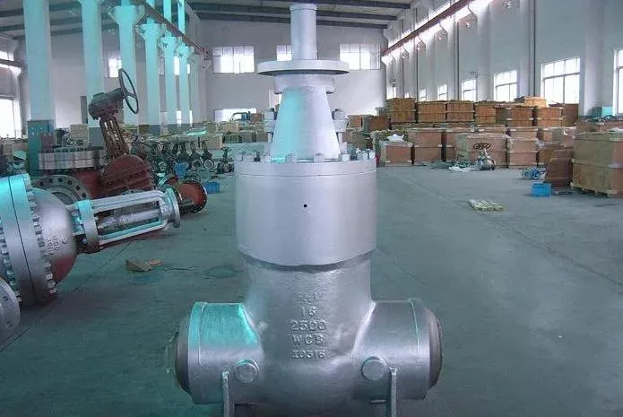
Pressure Seal API 6D Type
Pressure seal gate valves handle Class 600 through Class 4500 service, the high-pressure end of the spectrum. Available as flexible wedge or parallel slide designs, with cast or forged bodies in 2” to 24”. End connections are typically butt-weld or socket weld; flanged ends are possible but less common at these pressures.
The pressure seal bonnet is the defining feature: internal line pressure forces the bonnet gasket tighter against the seal ring. The higher the pressure, the tighter the seal. The opposite of a bolted bonnet, where bolt creep works against you over time.
Knife Type API 6D Gate Valve
Knife gate valves originated in the pulp and paper industry, where thick slurries would jam conventional gate valves. The thin, sharp-edged blade slices through fibrous and viscite media that would hang up on a wedge gate.
Like all gate valves, knife gates are strictly on/off. Never throttle with them; the partial-open flow will erode blade and seat in short order. They also open and close slowly by design to limit water hammer.
Knife gate valves are available in ductile iron through stainless steel, 2” to 24”, typically Class 150 or lower. Variants include soft-seated (elastomer, better shutoff), metal-seated (better for abrasive slurries), slide gate, and bonneted types.
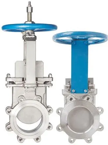 Metal seated knife gate valve
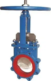 Soft seat knife gate valve.
A metal seated knife gate valve (left) and resilient, a soft-seated valve (right side).
The differences with standard design are:
| Feature | Standard Gate Valve | Knife Gate Valve |
|---|---|---|
| Connections | Flanged, butt weld, socket weld | Lugged or wafer (mainly) |
| Sealing | V-ring packing on shaft | Packing gland around gate |
| Flow direction | Bidirectional | Generally uni-directional |
| Profile | Bulky, refined | Smaller profile |
| Cost/Weight | Heavier, higher cost | Lighter, cheaper |
Gate Valve vs. Other Types of Valves
Gate Valve vs. Ball Valve
What is the difference between a gate and a ball valve?
| Feature | Gate Valve | Ball Valve |
|---|---|---|
| Closure element | Flat gate/wedge moves vertically | Spherical ball rotates 90° |
| Operation | Multi-turn (slow) | Quarter-turn (fast) |
| Flow path | Straight-through, full bore | Through ball bore |
| Pressure drop | Minimal when open | Low when open |
| Throttling | Not recommended (causes damage) | Possible with V-port or characterized trim |
| Sealing | Good, degrades with wear | Excellent (soft-seated) |
| Maintenance | More wear-prone, harder to repair | More durable, easier to maintain |
| Cost | Generally lower | Higher for full bore |
In practice, ball valves have largely replaced gate valves in new construction for sizes up to 12” because they are faster to operate, seal more reliably, and require less maintenance. Gate valves still hold their ground on large-bore pipelines (16”+), slurry service, and high-temperature applications where soft ball seats cannot survive.
Gate Valve vs. Globe Valve
What is the difference between a gate and a globe valve?
| Feature | Gate Valve | Globe Valve |
|---|---|---|
| Closure element | Flat gate/wedge moves vertically | Disk moves perpendicular to seat |
| Flow path | Straight-through, unobstructed | Tortuous path through baffle |
| Pressure drop | Minimal when open | Higher (due to flow path changes) |
| Throttling | Not recommended | Excellent |
| Flow control | On/off only | On/off and modulating |
| Operation speed | Slower | Moderate |
| Typical use | Long periods open or closed | Frequent operation, flow regulation |
The rule is simple: if you need to throttle or regulate flow, use a globe valve. If you need a low-pressure-drop isolation valve that sits open or closed for extended periods, use a gate valve. Globe valves have a higher pressure drop even when fully open because the flow path changes direction through the body; this is the tradeoff for precise flow control. Also note that globe valves are unidirectional (flow direction matters), while gate valves are bidirectional.
Gate Valve vs. Check Valve
These two serve completely different purposes, so comparing them is really about understanding when each applies.
| Feature | Gate Valve | Check Valve |
|---|---|---|
| Purpose | Manual on/off isolation | Automatic backflow prevention |
| Operation | Handwheel, gear, or actuator | Self-actuating (flow-driven) |
| Flow direction | Bidirectional | Unidirectional only |
| Operator input | Required to open/close | None; opens/closes with flow |
| Throttling | No | No |
A gate valve isolates. A check valve prevents reverse flow. They often work together. For example, on a pump discharge you will typically see a check valve (to prevent backflow when the pump trips) followed by a gate valve (for maintenance isolation). They are not interchangeable.
Gate Valve vs. Butterfly Valve
| Feature | Gate Valve | Butterfly Valve |
|---|---|---|
| Operation | Multi-turn (slow) | Quarter-turn (fast) |
| Size/weight | Large, heavy | Compact, light |
| Pressure drop | Minimal (full bore) | Some (disc in flow path) |
| Throttling | No | Yes (with proper disc design) |
| Cost (large sizes) | Higher | Significantly lower |
| Max pressure class | Class 2500+ | Typically Class 150-600 |
| Slurry service | Good | Poor (particles accumulate around disc) |
Butterfly valves have replaced gate valves in many low-to-medium-pressure applications (utility water, HVAC, cooling water) because they are lighter, cheaper, faster to operate, and take up far less space in a pipe rack. But they cannot match gate valves on high-pressure service or tight metal-to-metal shutoff. For Class 600+ or critical hydrocarbon isolation, gate valves remain the standard.
Gate Valve vs. Plug Valve
| Feature | Gate Valve | Plug Valve |
|---|---|---|
| Operation | Multi-turn (slow) | Quarter-turn (fast) |
| Flow path when open | Full bore, unobstructed | Through plug bore (some restriction) |
| Throttling | No | Limited (possible with special designs) |
| Lubrication | Not required | Lubricated types need periodic greasing |
| Size/weight | Larger, heavier | Compact, lighter |
| Typical service | Infrequent on/off isolation | Frequent switching, multi-port diverting |
Plug valves are common in chemical plants and gas distribution where quick operation and multi-port configurations are needed (e.g., 3-way or 4-way diverter service). Gate valves win on large-bore, high-pressure isolation where minimal pressure drop matters and operation is infrequent. In practice, the two rarely compete for the same application.
Gate Valve Diagram
The diagram below shows a typical API 600 gate valve assembly. The actual configuration depends on several design choices:
- Body: forged or cast steel
- Bonnet: bolted bonnet (standard) or pressure seal (Class 900+)
- Ends: flanged, butt-weld, socket weld, or threaded
- Wedge: solid, flexible, split, or parallel slide (see below)
- Stem: rising or non-rising (see below)
- Actuation: handwheel, gear, or powered (pneumatic, hydraulic, electric)
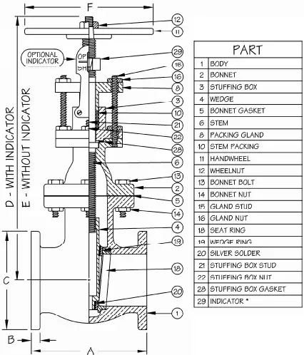 Gate valve parts
Gate valve diagram showing the key parts of a gate valve for piping
Gate valve parts
Gate valve diagram showing the key parts of a gate valve for piping
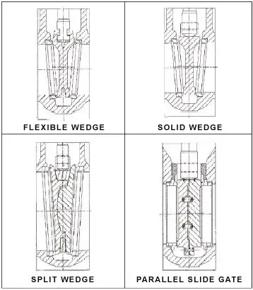
Gate Valve Wedge Types
The wedge is the closure element, the part that actually stops the flow. Its design has a direct impact on sealing, operability, and service life.

1. Solid Wedge
A single piece of metal. Simple, strong, and the cheapest to manufacture. Works well in general service but has one significant weakness: it cannot flex to accommodate thermal expansion. In high-temperature service, differential expansion between body and wedge can cause thermal binding: the wedge jams in the seats and the valve will not open. I have seen operators break handwheels trying to force open a thermally bound solid wedge valve on a steam line.
2. Flexible Wedge
The most common design in refinery service. A peripheral groove or cut allows the wedge to flex slightly as it seats, compensating for thermal expansion and minor seat misalignment. This is the standard choice for steam, hot oil, and any service with significant temperature swings. The tradeoff: the flex zone can develop fatigue cracks under severe thermal cycling.
3. Split Wedge (Parallel Disks)
Two separate disk halves, self-aligning against the seats. Eliminates thermal binding entirely because the disks float independently. Preferred where thermal binding is a real risk (high-temperature steam systems, for example). More complex and expensive than a solid or flexible wedge.
4. Slab Gate
A flat plate sliding between parallel seats. Not a wedge at all, strictly speaking, but it fills the same role. This is the standard design for API 6D pipeline gate valves because the full-bore, flat passage allows pigging and minimizes friction in viscous crude service.
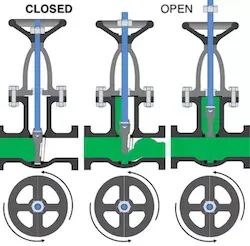
The image below shows how the wedge opens and closes by vertical movement (manual or actuated).
 Gate valves open and close function
The wedge seats between two angled (or parallel) faces perpendicular to the flow. When open, the bore is unobstructed.
Gate valves open and close function
The wedge seats between two angled (or parallel) faces perpendicular to the flow. When open, the bore is unobstructed.
The image below shows the four wedge types: solid wedge, flexible wedge, split wedge, and parallel slide.
 Wedge types for gate valves
Gate Valve Stem Types: Rising Stem vs Non-Rising
The stem connects the handwheel (or actuator) to the wedge. There are two main designs, and the choice between them matters more than most people think.

1. Rising Stem (OS&Y: Outside Screw and Yoke)
The stem physically rises out of the bonnet as the valve opens. You can see from across the pipe rack whether the valve is open or closed: stem up means open, stem down means closed. The threads are external, outside the flow stream, so they stay clean and lubricated.
Rising stem is the default choice for above-ground process plant service (API 600). The only drawback is vertical clearance: a 24” Class 300 gate valve needs over 10 feet of headroom when fully open.
2. Non-Rising Stem (NRS)
The stem stays in place; internal threads engage the gate and move it up or down. Compact. No external moving parts. But you cannot tell valve position by looking at it, and the threads are exposed to the process fluid, which causes accelerated wear in dirty or corrosive service.
NRS gate valves are standard for buried service (water mains, gas distribution) and anywhere headroom is limited (valve pits, underground vaults).
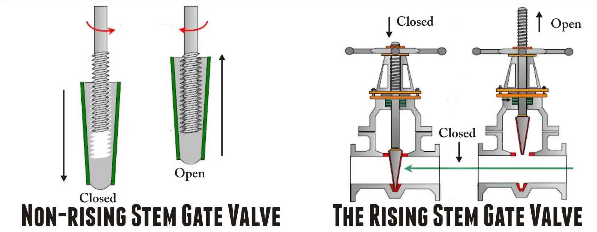
Rising and non rising stem of gate valves
3. Sliding Stem
A niche design where the stem translates linearly without rotating. Uncommon in standard gate valves but found in some specialty applications.
4. Rotating Rising Stem
Combines rising motion with rotation. The rotation helps reduce seat wear over time. Less common but worth considering for high-cycle applications where you need visual position indication.
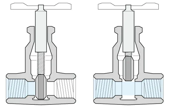
OS&Y vs. IS&Y Design
OS&Y (Outside Screw and Yoke): the stem rises visibly outside the body when the valve opens. The handwheel stays in a fixed position. You can confirm valve position from across the plant.
IS&Y (Inside Screw and Yoke): the stem threads are inside the body. The stem does not rise externally. Valve position is not visible without a position indicator.
 Gate valves OS&Y VS. IS&Y DESIGN
Gate Valve Materials
Body
The body of gate valves below 2 inches is generally made of forged steel (the most common body material grades are ASTM A105 for high-temperature service, ASTM A350 for low-temperature service, and, ASTM A182 F304/F316 for corrosive service).
The bodies of gate valves of bore sizes above 2 inches are, instead, made of cast steel (the main cast grades are ASTM A216 WCB for high-temperature service, ASTM A351 for low-temperature conditions, and ASTM A351 CF8 and CF8M - i.e. stainless steel 304 and 316 gate valves).
Trim
The removable and replaceable parts of the valve are collectively defined as “trim” (for a gate valve: seat, disc, backseat, and stem). The API 600 specification defines the following standard trim combinations:
| API TRIM # | BASE MATERIAL | MATERIAL FOR SEAT | MATERIAL FOR DISC | BACKSEATMATERIAL | MATERIAL FOR STEM |
|---|---|---|---|---|---|
| 1 | 410 | 410 | 410 | 410 | 410 |
| 2 | 304 | 304 | 304 | 304 | 304 |
| 3 | F310 | 310 | 310 | 310 | 310 |
| 4 | Hard 410 | Hard 410 | 410 | 410 | 410 |
| 5 | Hard faced | Stellite | Stellite | 410 | 410 |
| 5A | Hard faced | Ni-Cr | Ni-Cr | 410 | 410 |
| 6 | 410 and Cu-Ni | Cu-Ni | Cu-Ni | 410 | 410 |
| 7 | 410 and Hard 410 | Hard 410 | Hard 410 | 410 | 410 |
| 8 | 410 and Hardfaced | Stellite | 410 | 410 | 410 |
| 8A | 410 and Hardfaced | Ni-Cr | 410 | 410 | 410 |
| 9 | Monel | Monel | Monel | Monel | Monel |
| 10 | 316 | 316 | 316 | 316 | 316 |
| 11 | Monel | Stellite | Monel | Monel | Monel |
| 12 | 316 and Hardfaced | Stellite | 316 | 316 | 316 |
| 13 | Alloy 20 | Alloy 20 | Alloy 20 | Alloy 20 | Alloy 20 |
| 14 | Alloy 20 and Hardfaced | Stellite | Alloy 20 | Alloy 20 | Alloy 20 |
| 15 | 304 and Hardfaced | Stellite | Stellite | 304 | 304 |
| 16 | 316 and Hardfaced | Stellite | Stellite | 316 | 316 |
| 17 | 347 and Hardfaced | Stellite | Stellite | 347 | 347 |
| 18 | Alloy 20 and Hardfaced | Stellite | Stellite | Alloy 20 | Alloy 20 |
Material Selection
| TRIM | RECOMMENDED SERVICE |
|---|---|
| 13% Cr, Type 410 Stainless Steel | For oil and oil vapors and general services with heat treated seats and wedges. |
| 13% Cr, Type 410 plus Hardfacing | Universal trim for general service requiring long service life up to 1100°F (593°C).* |
| Type 316 Stainless | For liquids and gases that are corrosive to 410 Stainless Steel, up to 1000°F (537°C).* |
| Monel | For corrosive service to 842°F (450°C) such as acids, alkalies, salt solutions, etc. |
| Alloy 20 | For corrosive service such as hot acids -49°F to 608oF (-45°C to 320°C). |
| NACE | Specially treated 316 or 410 trim combined optionally with B7M Bolts and2HM nuts to meet NACE MR-01-75 requirements. |
| Full Stellite | Full hard-faced trim, suitable for abrasive & severe services up to 1200°F (650°C). |
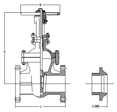
Gate Valve Dimensions
The tables show the dimensions and weights of API 600 gate valves (bolted bonnet / rising stem)
 Gate valve sizes
Class 150
Dimensions in inches (millimeters)
| Sizes | L | L1 (BW) | H (Open) | W |
|---|---|---|---|---|
| 2″ | 7 (180) | 8-1/2 (216) | 14-1/2 (368) | 8 (200) |
| 2-1/2″ | 7-1/2 (190) | 9-1/2 (241) | 17 (432) | 8 (200) |
| 3″ | 8 (200) | 11-1/8 (283) | 18 (457) | 8-7/8 (225) |
| 4″ | 9 (230) | 12 (305) | 22 (559) | 11 (279) |
| 5″ | 10 (254) | 15 (381) | 26 (660) | 12-3/4 (325) |
| 6″ | 10-1/2 (266) | 15-7/8 (403) | 30 (762) | 14 (356) |
| 8″ | 11-1/2 (290) | 16-1/2 (420) | 38-1/2 (978) | 14 (356) |
| 10″ | 13 (330) | 18 (457) | 46 (1168) | 18 (457) |
| 12″ | 14 (356) | 19 (502) | 55-1/4 (1403) | 20 (508) |
| 14″ | 15 (381) | 22 (559) | 60 (1524) | 21-1/2 (546) |
| 16″ | 16 (407) | 24 (610) | 74-7/8 (1902) | 24 (610) |
| 18″ | 17 (432) | 26 (660) | 79 (2007) | 27 (686) |
| 20″ | 18 (457) | 28 (711) | 87-1/2 (2223) | 28 (711) |
| 24″ | 20 (508) | 32 (813) | 105 (2667) | 31-1/2 (800) |
| 30″ | 24 (610) | 38 (965) | 130 (3302) | 43 (1092) |
| 36″ | 28 (711) | 44 (1118) | 162 (4115) | 51 (1295) |
| GEAR OPERATOR RECOMMENDED FOR SIZE 10″ AND ABOVE |
Class 300
Dimensions in inches (millimeters)
| SIZES | L/L1 | H (OPEN) | W |
|---|---|---|---|
| 2″ | 8-1/2 (216) | 16 (407) | 7-7/8 (200) |
| 2-1/2″ | 9-1/2 (241) | 17-3/8 (442) | 7-7/8 (200) |
| 3″ | 11-1/8 (283) | 19-3/4 (501) | 8-7/8 (225) |
| 4″ | 12 (305) | 23-3/8 (594) | 9-7/8 (251) |
| 5″ | 15 (381) | 23-3/4 (603) | 12-1/2 (318) |
| 6″ | 15-7/8 (403) | 32-1/8 (816) | 14 (356) |
| 8″ | 16-1/2 (420) | 41 (1041) | 15-3/4 (400) |
| 10″ | 18 (457) | 48-3/8 (1229) | 17-3/4 (451) |
| 12″ | 19-3/4 (501) | 57 (1448) | 20 (508) |
| 14″ | 30 (762) | 62-1/2 (1588) | 22 (559) |
| 16″ | 33 (838) | 69 (1753) | 25 (635) |
| 18″ | 36 (914) | 80-1/2 (2045) | 28 (711) |
| 20″ | 39 (991) | 91 (2311) | 35-1/2 (902) |
| 24″ | 45 (1143) | 120-1/2 (3061) | 43 (1092) |
| GEAR OPERATOR RECOMMENDED FOR SIZE 8″ AND ABOVE |
Class 600
Dimensions in inches (millimeters)
| SIZES | L/L1 | H (OPEN) | W |
|---|---|---|---|
| 2″ | 11-1/2 (290) | 16-1/2 (420) | 7-7/8 (200) |
| 2-1/2″ | 13 (330) | 18 (457) | 8-7/8 (225) |
| 3″ | 14 (356) | 20-1/8 (511) | 9-7/8 (251) |
| 4″ | 17 (432) | 25 (635) | 14 (356) |
| 5″ | 20 (508) | 30-1/2 (775) | 15-3/4 (400) |
| 6″ | 22 (559) | 33-5/8 (854) | 17-3/4 (451) |
| 8″ | 26 (660) | 42-3/8 (1076) | 20 (508) |
| 10″ | 31 (787) | 49 (1245) | 25 (635) |
| 12″ | 33 (838) | 68-1/2 (1740) | 27 (686) |
| 14″ | 35 (889) | 69 (1753) | 31-1/2 (800) |
| 16″ | 39 (991) | 74 (1880) | 35-1/2 (902) |
| 18″ | 43 (1092) | 84-1/4 (2140) | 43 (1092) |
| 20″ | 47 (1194) | 93-1/2 (2375) | 51 (1295) |
| 24″ | 55 (1397) | 110 (2794) | 51 (1295) |
| GEAR OPERATOR RECOMMENDED FOR SIZE 8″ AND ABOVE |
Class 900
Dimensions in inches (millimeters)
| SIZES | L/L1 | H (OPEN) | W |
|---|---|---|---|
| 2″ | 14-1/2 (368) | 26 (660) | 10-1/4 (260) |
| 3″ | 15 (381) | 26-3/8 (670) | 11-1/2 (292) |
| 4″ | 18 (457) | 30 (762) | 14 (356) |
| 6″ | 24 (610) | 40-3/4 (1035) | 20 (508) |
| 8″ | 29 (737) | 51 (1295) | 24 (610) |
| 10″ | 33 (838) | 61 (1549) | 27 (686) |
| 12″ | 38 (965) | 69-1/2 (1765) | 31-1/2 (800) |
| 14″ | 40-1/2 (1029) | 77 (1956) | 35-1/2 (902) |
| 16″ | 44-1/2 (1130) | 82-3/4 (2102) | 43 (1092) |
| GEAR OPERATOR RECOMMENDED FOR SIZE 6″ AND ABOVE |
Class 1500
Dimensions in inches (millimeters)
| SIZES | L/L1 | H (OPEN) | W |
|---|---|---|---|
| 2″ | 14-1/2 (368) | 21-1/2 (546) | 11-1/2 (290) |
| 3″ | 18-1/2 (470) | 27-1/8 (689) | 14 (356) |
| 4″ | 21-1/2 (546) | 31-1/2 (800) | 20 (508) |
| 6″ | 27-3/4 (705) | 45 (1143) | 24 (610) |
| 8″ | 32-3/4 (832) | 53-1/2 (1359) | 27 (686) |
| 10″ | 39 (991) | 65 (1651) | 35-1/2 (902) |
| 12″ | 44-1/2 (1130) | 74 (1880) | 43 (1092) |
| 14″ | 49-1/2 (1257) | 83-1/2 (2121) | 51 (1295) |
| 16″ | 54-1/2 (1384) | 88 (2235) | 63 (1600) |
| GEAR OPERATOR RECOMMENDED FOR SIZE 6″ AND ABOVE |
Class 2500
Dimensions in inches (millimeters)
| SIZES | L/L1 | H (OPEN) | W |
|---|---|---|---|
| 2″ | 17-3/4 (451) | 24-7/8 (632) | 12 (305) |
| 3″ | 22-3/4 (578) | 36 (914) | 20 (508) |
| 4″ | 26-1/2 (673) | 41-1/2 (1054) | 20 (508) |
| 6″ | 36 (914) | 57 (1448) | 24 (610) |
| 8″ | 40-1/4 (1022) | 63-3/8 (1610) | 24 (610) |
| GEAR OPERATOR RECOMMENDED FOR SIZE 6″ AND ABOVE |
Frequently Asked Questions
What is the difference between API 600 and API 602 gate valves?
API 600 covers cast steel gate valves in sizes NPS 1 and larger, with flanged or butt-welded ends for refinery and process plant service. API 602 covers compact forged steel gate valves in sizes NPS 4 and smaller, built for small-bore, high-pressure applications. API 602 valves have smaller facings, shorter end-to-end dimensions, and are rated per the socket-weld or threaded connection class.
Can a gate valve be used for throttling service?
No. Gate valves are strictly on/off isolation devices, not flow regulators. Operating a gate valve in a partially open position causes high-velocity flow across the gate disc, leading to vibration, erosion of the seating surfaces (wire drawing), and premature seal failure. For throttling, use a globe valve or control valve instead.
When should I specify a pressure seal bonnet instead of a bolted bonnet?
A pressure seal bonnet should be specified for gate valves in Class 900 and above (per API 600). Unlike bolted bonnets, pressure seal bonnets use internal pressure to tighten the body-bonnet seal ; the higher the pressure, the tighter the seal. This eliminates the risk of bolt relaxation and gasket creep at high pressures. Below Class 900, standard bolted bonnets with spiral wound gaskets are adequate.
What is the difference between a flexible wedge and a solid wedge gate valve?
A flexible wedge has a cut or groove in its center that allows slight deflection to accommodate thermal expansion and pipeline stresses, reducing the risk of seat binding. It is the preferred design for most oil & gas applications (steam, hot fluids). A solid wedge is a single-piece gate that is simpler and more reliable but prone to thermal binding in high-temperature service where the body and wedge expand at different rates.
Leave a Comment
Have a question or feedback? Send us a message.
Previous Comments
REQUIRE 3′ &4″ CAST STEEL BALL VALVE URGENTLY NEED PRICE : FOB/C&F NIGERIA !!! PEASE
Dear Sir We are an official partner for Saudi Electricity Co. So, We Need To know Price For one of your Company Product , Could You Send us an official Quotation with Price, Full DataSheets and Delivery Time about This Product with The Following Data .. – Shipping and Deliver : Riyadh – Saudi Arabia Kindly Reply us as soon as Possible that's So urgent .. ============== *PROUDCT DATA* ============== Item No : 901415094 WEDGE,BULK NOUN: ADDITIONAL DATA: PARENT EQUIPMENT FUNCTION-: LOW PRESSURE VALVE WEDGE CLASS 150 GATE SW END MAT ERIAL-: A217-CA15+STL USED IN SHUQAIQ S TEAM POWER PLANT S & S VALVES: P/N#SNSD-2013-1030DN40 SW,POS#3 Quantity : 1 EA Item No : 901415107 WEDGE,BULK NOUN: ADDITIONAL DATA: PARENT EQUIPMENT FUNCTION-: LOW PRESSURE VALVE WEDGE CLASS 600 GATE SW END MAT ERIAL-: A217-CA15+STL USED IN SHUQAIQ S TEAM POWER PLANT S & S VALVES: P/N#SNSD-2013-1030DN40 SWCLASS600,POS#3 Quantity : 1 EA Item No : 901415120 WEDGE,BULK NOUN: ADDITIONAL DATA: PARENT EQUIPMENT FUNCTION-: LOW PRESSUR E VALVE WEDGE CLASS 600 GATE SW END MAT ERIAL-: A217-CA15+STL USED IN SHUQAIQ S TEAM POWER PLANT S & S VALVES: P/N#SNSD-2013-1030DN25 SW,POS#3 Quantity : 1 EA Item No : 901415133 WEDGE,BULK NOUN: ADDITIONAL DATA: PARENT EQUIPMENT FUNCTION-: LOW PRESSUR E VALVE WEDGE CLASS 600 GATE SW END MAT ERIAL-: A217-CA15+STL USED IN SHUQAIQ S TEAM POWER PLANT S & S VALVES: P/N#SNSD-2013-1030WEDGEDN25,POS#3 Quantity : 1 EA Item No : 901415209 WEDGE,BULK NOUN: ADDITIONAL DATA: PARENT EQUIPMENT FUNCTION-: LOW PRESSUR E VALVE WEDGE CLASS 1500 GATE SW END MA TERIAL-: A217-CA15+STL USED IN SHUQAIQ STEAM POWER PLANT S & S VALVES: P/N#SNSD-2013-1030DN40,POS#3 Quantity : 1 EA Item No : 901415222 WEDGE,BULK NOUN: ADDITIONAL DATA: PARENT EQUIPMENT FUNCTION-: LOW PRESSUR E VALVE WEDGE CLASS 600 GATE SW END MAT ERIAL-: A217-CA15+STL USED IN SHUQAIQ S TEAM POWER PLANT S & S VALVES: P/N#SNSD-2013-1030DN25GATE,POS#3 Quantity : 1 EA Item No : 901498938 CAPACITOR:FIXED, 2 MICRO F,6000 VDC,ALUM CAPACITOR,FIXED: CAPACITANCE: 2 MICRO F; VOLTAGE: 6000 VDC; STYLE:ALUM CANISTER; TOLERANCE:MINUS/PLUS 10 SIZE:130 MM WD X 100 MM LG X 50 MM DP; STANDARD/SPECIFICATION:IEC 60384-4 ADDITIONAL DATA: ITEM ADDITIONAL DESCRIPTION: ; SYSTEM PARENT EQUIPMENT INFORMATION: USED FOR SHUQAIQ STEAM POWER PLANT. VISHAY (FM): P/N#ER60-205 Quantity : 1 EA Item No : 901499024 AMMETER:ANALOG,PANEL MOUNT SQUARE FACE,0 AMMETER,ANALOG: STYLE: PANEL MOUNT SQUARE FACE; RANGE: 0 TO 2000 A; STANDARD/SPECIFICATION: CE, UL LISTED; ADDITIONAL DATA: ITEM ADDITIONAL DATA: CLASS 1.5, CT RA TING 2000:1 A; SYSTEM PARENT EQUIPMENT DETAILS: USED FOR AL SHUQIQ POWER PLANT SUBSTATION. GANZ: P/N#72LA 2000A(AC Quantity : 2 EA Item No : 901499025 AMMETER:ANALOG,PANEL MOUNT SQUARE FACE,0 AMMETER,ANALOG: STYLE: PANEL MOUNT SQUARE FACE; RANGE: 0 TO 400 A; STANDARD/SPECIFICATION: CE, UL LISTED; ADDITIONAL DATA: ITEM ADDITIONAL DATA: CLASS 1.5, CT RA TING 400:1 A; SYSTEM PARENT EQUIPMENT DETAILS: USED FOR AL SHUQIQ POWER PLANT SUBSTATION. GANZ: P/N#72LA 400A(AC) Quantity : 2 EA Item No : 4602BF661 METER:FREQUENCY,ANALOG READOUT,PANEL MOU METER,FREQUENCY: READOUT: ANALOG; STYLE: PANEL MOUNT; RANGE: 55 TO 60 TO 65 HZ; ADDITIONAL DATA: DOUBLE REED, WITH TWO INDEPENDENT VIBRA TING REED MECHANISMS, 96 MM X 96 MM SIZ E, 3240F, EH726, FZ16-2 ROWS OF 21, IL 731- 100- 120 VAC, LB1-CONDITIONALLY TROPIC PROOF, FQ1S5C. UNIDENTIFIED MANUFACTURER – SOA: ZF-96-2 Quantity : 4 EA
Dear Sir, please post your RFQ in the RFQ section of the site
Nice Information Regarding Gate Valve
1. VALVE,GATE: SIZE: 2-1/2″ DESIGN RATING: 175 PSI (12.1 BAR) WWP CONNECTION: THD BODY MATERIAL: BRZ ASTM B62 TYPE: SOLID WEDGE STEM DESIGN: NON-RISING STEM OPERATED: HANDWHEEL STYLE: THD BONNET TRIM: BRZ ASTM B62 BONNET, SILICON BRZ ASTM B371 ALLOYC69430 SOFTGOODS: NON ASBESTOS ARAMID FIBERS W/GRAPHITE PACKINGTEXT:FIRE FITTING SYSTEM, HOSE MFG VINTAGE BRONZE POWHATAN RANSON W VAPART # 19-281 2. VALVE,GATE: SIZE: 3″ DESIGN RATING: 600 LB CONNECTION: RF FLG BODY MATERIAL: ASTM A217 WC6 – NORM.&TEMP. TYPE: FLEXIBLE WEDGE STEM DESIGN: RISING STEM, OUTSIDE SCREW PORT: FULL OPERATED: HANDWHEEL STYLE: BOLTED BONNET, OS&Y TRIM: 316L SS TRIM SOFTGOODS: 13-CR ASTM A182 GR F6 TRIM, STELLITED SEAT MANUFACTURING STANDARD: GRAPHITE GLAND PACKING MFG VITAS(S.P.A):00-GA-E-60146