Blind Flange Sizes (EN 1092-1)
EN 1092-1 Blind Flange Dimensions and Weights
What Is a “Type 05” EN 1092-1 Blind Flange?
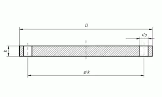
“Type 05” according to EN 1092-1 designates a blind flange: a solid disc with no bore, used to seal the end of a piping system or isolate a pipeline section. The EN 1092-1 standard specifies dimensions, tolerances, and material requirements for flanges prevalent in European and international piping systems.
A blind flange is a solid disc - no bore, no flow passage. It bolts to a mating flange with a gasket to seal the end of a pipeline, isolate a section for maintenance, or cap an unused nozzle. During hydrostatic testing, blinds close off the test section boundaries. Sizes range from DN 15 to DN 2000+ in pressure ratings PN 6 through PN 100.
Because blind flanges take the full line pressure across their entire face (unlike other flanges where pressure acts only on the bore area), they’re the thickest flange type for any given size and rating.
Dimensions and Weights of EN 1092-1 Blind Flanges
Blind Flange PN 6
PN 6 blind flange dimensions (EN 1092-1 type 05) with stud metric bolts and nuts requirements (all sizes are in millimeters unless otherwise specified)
| DN | k | D | b | d2 | Thread | Bolt Holes | Weight (KG) |
|---|---|---|---|---|---|---|---|
| 15 | 55 | 80 | 12 | 11 | M10 | 4 | 0,438 |
| 20 | 65 | 90 | 14 | 11 | M10 | 4 | 0,657 |
| 25 | 75 | 100 | 14 | 11 | M10 | 4 | 0,821 |
| 32 | 90 | 120 | 14 | 14 | M12 | 4 | 1,180 |
| 40 | 100 | 130 | 14 | 14 | M12 | 4 | 1,390 |
| 50 | 110 | 140 | 14 | 14 | M12 | 4 | 1,620 |
| 65 | 130 | 160 | 14 | 14 | M12 | 4 | 2,140 |
| 80 | 150 | 190 | 16 | 18 | M16 | 4 | 3,430 |
| 100 | 170 | 210 | 16 | 18 | M16 | 4 | 4,220 |
| 125 | 200 | 240 | 18 | 18 | M16 | 8 | 6,100 |
| 150 | 225 | 265 | 18 | 18 | M16 | 8 | 7,510 |
| 200 | 280 | 320 | 20 | 18 | M16 | 8 | 12,300 |
| 250 | 335 | 375 | 22 | 18 | M16 | 12 | 18,500 |
| 300 | 395 | 440 | 22 | 22 | M20 | 12 | 25,500 |
| 350 | 445 | 490 | 22 | 22 | M20 | 12 | 31,800 |
| 400 | 495 | 540 | 22 | 22 | M20 | 16 | 38,500 |
| 450 | 550 | 595 | 24 | 22 | M20 | 16 | 51,200 |
| 500 | 600 | 645 | 24 | 22 | M20 | 20 | 60,100 |
| 600 | 705 | 755 | 30 | 26 | M24 | 20 | 103,000 |
| 700 | 810 | 860 | 40 | 26 | M24 | 24 | 178,000 |
| 800 | 920 | 975 | 44 | 30 | M27 | 24 | 252,000 |
| 900 | 1020 | 1075 | 48 | 30 | M27 | 24 | 336,000 |
| 1000 | 1120 | 1175 | 52 | 30 | M27 | 28 | 435,000 |
| 1200 | 1340 | 1405 | 60 | 33 | M30 | 32 | 717,000 |
| 1400 | 1560 | 1630 | 68 | 36 | M33 | 36 | 1.094,000 |
| 1600 | 1760 | 1830 | 76 | 36 | M33 | 40 | 1.545,000 |
| 1800 | 1970 | 2045 | 84 | 39 | M36 | 44 | 2.131,000 |
| 2000 | 2180 | 2265 | 92 | 42 | M39 | 48 | 2.862,000 |
Blind Flange PN 10
PN 10 blind flange dimensions (EN 1092-1 type 05) with stud metric bolts and nuts requirements (all sizes are in millimeters unless otherwise specified)
| DN | k | D | b | d2 | Thread | Bolt Holes | Weight (KG) |
|---|---|---|---|---|---|---|---|
| 200 | 295 | 340 | 24 | 22 | M20 | 8 | 16,500 |
| 250 | 350 | 395 | 26 | 22 | M20 | 12 | 24,100 |
| 300 | 400 | 445 | 26 | 22 | M20 | 12 | 30,800 |
| 350 | 460 | 505 | 26 | 22 | M20 | 16 | 39,600 |
| 400 | 515 | 565 | 26 | 26 | M24 | 16 | 49,400 |
| 450 | 565 | 615 | 28 | 26 | M24 | 20 | 63,000 |
| 500 | 620 | 670 | 28 | 26 | M24 | 20 | 75,200 |
| 600 | 725 | 780 | 34 | 30 | M27 | 20 | 124,000 |
| 700 | 840 | 895 | 38 | 30 | M27 | 24 | 183,000 |
| 800 | 950 | 1015 | 48 | 33 | M30 | 24 | 297,000 |
| 900 | 1050 | 1115 | 50 | 33 | M30 | 28 | 374,000 |
| 1000 | 1160 | 1230 | 54 | 36 | M33 | 28 | 492,000 |
| 1200 | 1380 | 1455 | 66 | 39 | M36 | 32 | 842,000 |
Blind Flange PN 16
PN 16 blind flange dimensions (EN 1092-1 type 05) with stud metric bolts and nuts requirements (all sizes are in millimeters unless otherwise specified)
| DN | k | D | b | d2 | Thread | Bolt Holes | Weight (KG) |
|---|---|---|---|---|---|---|---|
| 15 | 65 | 95 | 16 | 14 | M12 | 4 | 0,813 |
| 20 | 75 | 105 | 18 | 14 | M12 | 4 | 1,140 |
| 25 | 85 | 115 | 18 | 14 | M12 | 4 | 1,380 |
| 32 | 100 | 140 | 18 | 18 | M16 | 4 | 2,030 |
| 40 | 110 | 150 | 18 | 18 | M16 | 4 | 2,350 |
| 50 | 125 | 165 | 18 | 18 | M16 | 4 | 2,880 |
| 65 | 145 | 185 | 18 | 18 | M16 | 4 | 3,643 |
| 80 | 160 | 200 | 20 | 18 | M16 | 8 | 4,610 |
| 100 | 180 | 220 | 20 | 18 | M16 | 8 | 5,650 |
| 125 | 210 | 250 | 22 | 18 | M16 | 8 | 8,130 |
| 150 | 240 | 285 | 22 | 22 | M20 | 8 | 10,500 |
| 200 | 295 | 340 | 24 | 22 | M20 | 12 | 16,200 |
| 250 | 355 | 405 | 26 | 26 | M24 | 12 | 25,000 |
| 300 | 410 | 460 | 28 | 26 | M24 | 12 | 35,100 |
| 350 | 470 | 520 | 30 | 26 | M24 | 16 | 48,000 |
| 400 | 525 | 580 | 32 | 30 | M27 | 16 | 63,500 |
| 450 | 585 | 640 | 40 | 30 | M27 | 20 | 96,600 |
| 500 | 650 | 715 | 44 | 33 | M30 | 20 | 133,000 |
| 600 | 770 | 840 | 54 | 36 | M33 | 20 | 226,000 |
| 700 | 840 | 910 | 58 | 36 | M33 | 24 | 285,000 |
| 800 | 950 | 1025 | 62 | 39 | M36 | 24 | 388,000 |
| 900 | 1050 | 1125 | 64 | 39 | M36 | 28 | 483,000 |
| 1000 | 1170 | 1255 | 68 | 42 | M39 | 28 | 640,000 |
Tolerances for EN 1092-1 Blind Flanges
EN 1092-1 specifies manufacturing tolerances for all critical dimensions. The key tolerances for blind flanges:
| Dimension | Tolerance | Notes |
|---|---|---|
| Outside diameter (D) | ±1% of D (min ±2 mm) | Tighter for small sizes |
| Thickness (b) | +0.4 mm per 10 mm thickness, -0 mm | Always positive tolerance - flanges can be thicker but not thinner than nominal |
| Bolt circle diameter (k) | ±0.5 mm to ±2 mm depending on size | Critical for bolt hole alignment with mating flange |
| Bolt hole diameter (d2) | +1 mm / -0 mm | Holes are oversized to allow for bolt alignment |
| Bolt hole position | ±0.5° angular | Holes must be equally spaced, straddling the vertical centerline |
| Face flatness | 0.2 mm for gasket contact area | Measured with a straight edge across the sealing face |
Note that thickness tolerance is one-sided (positive only) - a blind flange may be slightly thicker than the nominal dimension in the tables above, but never thinner. This is a safety margin, since blind flanges see full pressure load across the entire face diameter.
Leave a Comment
Have a question or feedback? Send us a message.
Previous Comments
Can you explain to me why some blind flanges have a flat face and some have a slightly raised face? if I have one that has the dame DN# an same PN rating but one is flat and the other has a slightly raised face are they the same part? Also what does it mean when the rating is stamped as PN10/16/25/40 instead of just PN16