NDT Methods: UT, RT, MT, PT, VT
Non-Destructive Testing (NDT)
NDT techniques detect defects in materials and welds without destroying the test piece. This allows inspection of every item (unlike destructive testing, which sacrifices samples) and continued use after testing. In oil and gas piping, NDT is governed primarily by ASME B31.3 (process piping), ASME Section V (examination methods), and ASME Section VIII (pressure vessels).
The terms NDT and NDE (Non-Destructive Examination) are used interchangeably in industry. ASME codes generally use “examination,” while API and ISO standards tend to use “testing” or “inspection.”
Detectable Flaws
| Defect Type | Description |
|---|---|
| Cracks | Surface or subsurface fractures from manufacturing, service, or fatigue |
| Inclusions | Foreign materials embedded during production |
| Porosity | Voids or gas pockets weakening the structure |
| Laminations | Layer separations in composites or rolled products |
| Weld defects | Incomplete penetration, lack of fusion, undercut, porosity |
| Corrosion | Material loss from chemical attack |
| Erosion | Surface wear from abrasive substances |
| Dimensional variations | Thickness deviations from spec |
Who Performs NDT?
NDT technicians require certification from recognized bodies such as ASNT (American Society for Nondestructive Testing). Certification levels (I, II, III) indicate increasing expertise and authority to interpret results.
Third-party inspection agencies (SGS, Lloyd’s, DNV, Bureau Veritas) provide independent NDT services for critical applications where unbiased results are required (oil & gas, aerospace, nuclear, and construction).
NDT vs. Destructive Testing
| Aspect | NDT | Destructive Testing |
|---|---|---|
| Effect on sample | No damage; item remains usable | Sample destroyed |
| Sample rate | Can test 100% of production | Sample-based only |
| Data type | Defect detection and location | Ultimate strength, failure mode |
| Application | Ongoing inspection, quality control | Design verification, material qualification |
Selecting the Right NDT Method
| Need | Recommended Method |
|---|---|
| Internal flaws in thick materials | UT (Ultrasonic) |
| Internal weld structure | RT (Radiographic) |
| Surface cracks on ferromagnetic steel | MT (Magnetic Particle) |
| Surface cracks on non-magnetic materials | PT (Penetrant Testing) |
| Thin-wall tubing inspection | ET (Eddy Current) |
| Quick initial assessment | VT (Visual Testing) |
| Accurate flaw sizing for fitness-for-service | TOFD |
| Cross-sectional weld imaging | Phased Array UT |
NDT allows inspection of every item without destroying the test piece, unlike destructive testing which sacrifices samples. The six main methods each detect different defect types: VT for surface defects, PT for surface-breaking cracks on non-magnetic materials, MT for surface and near-surface flaws on ferromagnetic steel, UT for internal flaws, RT for internal weld structure, and ET for thin-wall tubing inspection. Advanced techniques such as TOFD, phased array UT, and digital radiography offer improved accuracy, speed, and permanent records.
The 6 Key NDT Methods
| Method | Abbreviation | Detects | Materials |
|---|---|---|---|
| Visual Testing | VT | Surface defects | All |
| Liquid Penetrant | PT / LPT / DPI | Surface-breaking cracks | Non-porous only |
| Magnetic Particle | MT / MPI / MPT | Surface and near-surface | Ferromagnetic only |
| Ultrasonic | UT | Internal and surface | Most metals |
| Radiographic | RT / RX | Internal structure | Dense materials |
| Eddy Current | ET / ECT | Surface and subsurface | Conductive only |
Visual Testing (VT)
The simplest and cheapest NDT method, and the first step in any inspection regime. Inspectors examine surfaces with the naked eye or magnifying tools to identify visible defects. All welds must undergo VT as a minimum requirement per ASME B31.3 para. 344.2.
| Requirement | Details |
|---|---|
| Standard | ASME Section V, Article 9 |
| Surface preparation | Clean thoroughly before examination |
| Defect types | Cracks, porosity, undercut, misalignment, corrosion |
| Limitation | Surface defects only; cannot detect subsurface flaws |
| Light requirements | Minimum 1000 lux (100 fc) at the examination surface |
| Follow-up | If defects found, additional NDT methods determine extent |
Liquid Penetrant Testing (PT)
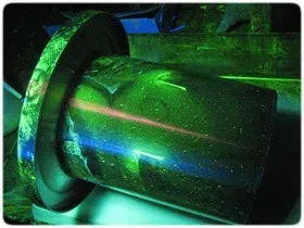
PT testing detects surface-breaking defects in non-porous materials (metals, plastics, ceramics) using capillary action to draw colored dye into cracks. It is the standard surface examination method for austenitic stainless steel, duplex, nickel alloys, and aluminum where MT cannot be used.
| Step | Action |
|---|---|
| 1. Clean | Remove all contaminants from surface |
| 2. Apply penetrant | Spray or brush colored dye onto surface |
| 3. Dwell | Allow time for penetrant to seep into defects (typically 10-30 minutes) |
| 4. Remove excess | Wipe off surface penetrant with solvent/emulsifier |
| 5. Apply developer | White powder draws penetrant out of defects |
| 6. Inspect | Colored indications reveal crack locations |
Penetrant types: Type I (fluorescent, viewed under UV-A light, higher sensitivity) and Type II (visible dye, red contrast, used in field conditions). Most piping fabrication shops use Type II visible dye for convenience; Type I fluorescent is specified for critical components such as high-pressure valves and nuclear piping.
| Pros | Cons |
|---|---|
| Simple, low-cost | Surface defects only |
| Works on non-magnetic materials | Not for porous materials |
| Detects cracks invisible to naked eye | Requires clean, smooth surface |
| Portable, no power needed (visible dye) | Temperature sensitive (typically 10-52 deg C) |
Magnetic Particle Testing (MT)
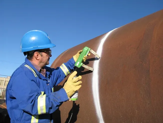
MT testing detects surface and near-surface flaws in ferromagnetic materials only (carbon steel, low-alloy steel, ferritic/martensitic stainless steel). The component is magnetized, and magnetic particles accumulate at flux leakage points caused by defects.
| Step | Action |
|---|---|
| 1. Magnetize | Apply magnetic field using yoke, prods, or coil |
| 2. Apply particles | Spray dry powder or wet suspension onto surface |
| 3. Inspect | Particles cluster at defect locations, forming visible indications |
| 4. Demagnetize | Remove residual magnetism (required by most specifications) |
Magnetization techniques: AC yoke (most common in field), DC prods (deeper penetration but risk arc strikes), and multi-directional units (detect flaws in all orientations in one shot). For weld inspection, two magnetization passes at 90 degrees are typically required to detect defects in both longitudinal and transverse orientations.
| Pros | Cons |
|---|---|
| Detects surface and near-surface defects | Ferromagnetic materials only |
| Fast, cost-effective | Cannot detect deep internal flaws |
| Portable equipment available | Component must be demagnetized after test |
| Works through thin coatings (up to ~50 microns) | Requires two passes for full coverage |
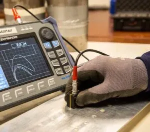
Ultrasonic Testing (UT)
UT uses high-frequency sound waves (typically 1-10 MHz) to detect internal flaws and measure wall thickness. A transducer probe sends ultrasonic pulses into the material; reflections from defects or back walls are analyzed to determine flaw location, size, and characteristics.
| Step | Action |
|---|---|
| 1. Setup | Apply couplant (gel/oil) and position probe on surface |
| 2. Calibrate | Set range and sensitivity using reference blocks with known reflectors |
| 3. Transmit | Probe sends ultrasonic waves into material |
| 4. Receive | Probe detects reflected waves from defects or back wall |
| 5. Analyze | Software calculates defect location, size, and depth |
Conventional UT techniques: Straight beam (0-degree, for thickness measurement and lamination detection) and angle beam (45, 60, or 70 degrees, for weld examination). Angle beam UT is the standard volumetric examination method for butt welds in process piping per ASME B31.3.
| Pros | Cons |
|---|---|
| Detects internal and surface flaws | Requires skilled operator |
| Accurate depth/size measurement | Surface must be accessible and smooth |
| Portable, no radiation hazard | Coarse-grained materials challenging (cast SS, Inconel) |
| Real-time results | Calibration required for each setup change |
| Single-sided access sufficient | No permanent image record (conventional UT) |
Radiographic Testing (RT)
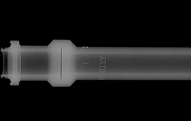
RT uses X-rays or gamma rays to create images of a component’s internal structure. Radiation passes through the material and exposes film or a digital detector on the opposite side. Defects appear as density variations in the image.
| Step | Action |
|---|---|
| 1. Setup | Position radiation source on one side, film/detector on opposite |
| 2. Expose | Activate source; radiation penetrates component |
| 3. Process | Develop film or process digital image |
| 4. Interpret | Trained interpreter examines image for defect indications per acceptance criteria |
Radiation sources: X-ray tubes (adjustable energy, better image quality, needs power supply) and gamma ray isotopes: Ir-192 (for steel up to ~75 mm) and Co-60 (for thicker sections). Gamma sources are portable and need no electricity, making them standard for field work on pipelines.
| Pros | Cons |
|---|---|
| Permanent record of inspection | Radiation safety requirements (exclusion zones) |
| Detects internal voids, inclusions, porosity | Access needed to both sides of the component |
| Good for weld inspection | Slower than UT (film processing time) |
| Works on most materials | Equipment cost, licensing, and storage |
| Image is intuitive to interpret | Poor at detecting planar defects oriented parallel to beam |
(Source: Peter Smith, Piping Materials Selection and Applications, 2004)
Eddy Current Testing (ET)
 Eddy current testing probe
Eddy current testing finds surface and subsurface defects in conductive materials only through electromagnetic induction. A probe coil generates alternating current that induces eddy currents in the test material; defects cause measurable impedance changes.
| Step | Action |
|---|---|
| 1. Setup | Position probe coil near material surface |
| 2. Generate | Alternating field induces eddy currents in material |
| 3. Detect | Defects/thickness changes alter impedance |
| 4. Analyze | Signal variations indicate defect location and size |
| Pros | Cons |
|---|---|
| No couplant required | Conductive materials only |
| Fast inspection speed | Limited penetration depth (typically < 5 mm) |
| Detects small surface cracks | Sensitive to lift-off variations |
| Excellent for tube/heat exchanger inspection | Interpretation requires experience |
ET testing is particularly effective for inspecting heat exchanger tubes, aircraft structures, and thin-wall tubing where rapid, automated inspection is needed. Internal Rotary Inspection Systems (IRIS) combine UT with a rotating mirror for tube inspection where ET sensitivity is insufficient.
Advanced NDT Methods
Advanced techniques offer improved accuracy, permanent digital records, and faster inspection speeds compared to conventional methods.
Time-of-Flight Diffraction (TOFD)
TOFD uses two angled ultrasonic probes (one transmitter, one receiver) positioned on opposite sides of a weld. Instead of measuring reflected pulse amplitude (like conventional UT), TOFD measures the arrival time of diffracted signals from flaw tips. This provides accurate through-wall flaw sizing independent of flaw orientation.
| Feature | Details |
|---|---|
| Standard | ASME Section V, Article 4; EN ISO 10863 |
| Accuracy | Flaw height sizing to +/- 1 mm |
| Coverage | Full weld volume in a single scan pass |
| Record | Permanent encoded digital image (D-scan) |
| Limitation | Dead zones at OD and ID surfaces (supplemented with PAUT or pulse-echo) |
Phased Array UT (PAUT)
Phased array probes contain multiple piezoelectric elements (typically 16-64) pulsed with controlled time delays. This allows electronic beam steering, focusing, and sweeping without moving the probe. PAUT produces cross-sectional images (S-scans) that are similar to RT images but without radiation.
| Feature | Details |
|---|---|
| Standard | ASME Section V, Article 4; ASME CC 2235 |
| Probe elements | 16 to 128 elements typical |
| Output | S-scan (sectorial), B-scan (side view), C-scan (plan view) |
| Speed | 3-5x faster than conventional angle beam UT |
| Acceptance | ASME, API, EN codes accept PAUT as RT alternative |
Digital Radiography (DR) and Computed Radiography (CR)
Digital radiography replaces conventional film with flat-panel detectors (DR) or phosphor imaging plates (CR). Benefits include instant image availability, adjustable contrast/brightness, reduced radiation dose, and elimination of chemical film processing. Digital images are stored electronically and can be reviewed remotely.
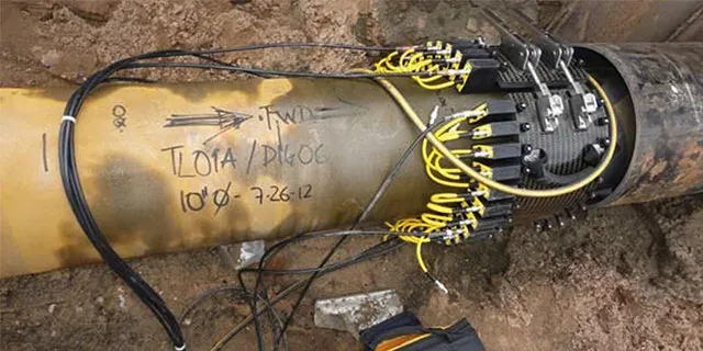
Automated Ultrasonic Testing (AUT)
AUT uses mechanized scanners to drive ultrasonic probes around a weld, producing encoded and repeatable data. AUT typically combines PAUT, TOFD, and conventional UT channels in a single scan pass. It is the standard inspection method for cross-country pipeline girth welds under API 1104 and is increasingly specified for shop-fabricated pressure vessel and piping welds.
NDT Method Comparison Table
| Criterion | VT | PT | MT | UT | RT | ET |
|---|---|---|---|---|---|---|
| Defect location | Surface | Surface only | Surface + near-surface | Internal + surface | Internal | Surface + near-surface |
| Ferromagnetic steel | Yes | Yes | Yes | Yes | Yes | Yes |
| Austenitic SS / Nickel | Yes | Yes | No | Difficult | Yes | Yes |
| Aluminum / Non-ferrous | Yes | Yes | No | Yes | Yes | Yes |
| Minimum detectable size | ~1 mm visible | ~1 micron width | ~0.5 mm | ~1 mm | ~2% of wall thickness | ~0.5 mm |
| Subsurface capability | No | No | Shallow (~3 mm) | Full thickness | Full thickness | Shallow (~5 mm) |
| Permanent record | Photos/reports | Photos | Photos | Digital (PAUT/TOFD) | Film or digital image | Strip chart/digital |
| Radiation hazard | No | No | No | No | Yes | No |
| Relative cost | Low | Low | Low-Medium | Medium | Medium-High | Medium |
| Speed | Fast | Slow (dwell time) | Fast | Medium | Slow | Fast |
| Personnel level (min.) | VT Level II | PT Level II | MT Level II | UT Level II | RT Level II | ET Level II |
NDT Selection Guide by Defect Type
Selecting the right NDT method depends on the defect being sought, the material, and access conditions.
| Defect Type | Primary Method | Secondary Method | Notes |
|---|---|---|---|
| Surface cracks (CS/alloy) | MT | VT | MT detects tighter cracks than VT |
| Surface cracks (SS/nickel) | PT | VT | MT not applicable to non-magnetic alloys |
| Subsurface cracks | UT (angle beam) | RT | UT better for planar flaws |
| Porosity | RT | UT | RT more sensitive to scattered porosity |
| Slag inclusions | RT | UT | Volumetric defects show clearly on RT |
| Lack of fusion | UT | TOFD/PAUT | Planar defect; RT often misses if parallel to beam |
| Incomplete penetration | RT | UT | Consistent orientation makes RT effective |
| Wall thinning / corrosion | UT (straight beam) | ET | UT measures remaining thickness precisely |
| Laminations in plate | UT (straight beam) | — | RT cannot detect laminations (parallel to beam) |
| Heat exchanger tube defects | ET | IRIS (UT) | ET is fast and automated for large tube bundles |
Personnel Qualification Levels
NDT personnel must be certified per ASNT SNT-TC-1A (employer-based, North America), ASNT CP-189 (central certification), or ISO 9712 (international). Certification is method-specific, so an inspector qualified in UT is not automatically qualified in RT.
| Level | Authority | Typical Requirements |
|---|---|---|
| Level I | Perform tests under direct supervision of Level II or III; cannot interpret or accept/reject | Classroom training + OJT hours (method-specific); pass general, specific, and practical exams |
| Level II | Set up equipment, perform tests, interpret results, accept/reject per procedures, train Level I | Additional training + OJT hours beyond Level I; pass all exams; most project specifications require Level II minimum |
| Level III | Develop procedures, establish techniques, interpret codes, manage NDT programs, train all levels | Extensive experience; pass ASNT Level III Basic and Method exams; typically requires engineering background |
ASME B31.3 Examination Requirements
ASME B31.3 specifies minimum examination requirements based on fluid service category. Project piping specifications and pipe class sheets may increase these minimums but never reduce them.
Examination Extent by Fluid Service
| Fluid Service | Butt Welds (RT or UT) | Branch Welds | Socket/Fillet Welds | Hardness Testing |
|---|---|---|---|---|
| Normal (Category D) | 5% random | VT 100% | VT 100% | Per WPS |
| Normal | 5% random | VT 100% | VT 100% | Per WPS |
| Category M (lethal) | 100% RT or UT | 100% MT or PT | 100% MT or PT | 100% |
| High-Pressure | 100% RT or UT | 100% MT or PT | 100% MT or PT | 100% |
| Severe Cyclic | 100% RT or UT | 100% MT or PT | 100% MT or PT | 100% |
Typical Project Examination by Pipe Class
In practice, EPC companies define examination percentages in project piping specifications that exceed B31.3 minimums based on pipe class criticality.
| Pipe Class Criticality | Butt Weld RT/UT | Socket/Fillet MT or PT | Visual |
|---|---|---|---|
| Utility (water, air) | 5-10% | 0-10% | 100% |
| Standard process | 10-20% | 10-20% | 100% |
| High-temperature / HP | 100% | 100% | 100% |
| Lethal / toxic service | 100% | 100% | 100% |
| Sour service (NACE) | 100% | 100% | 100% + hardness |
Acceptance Criteria Overview
NDT results are evaluated against acceptance criteria defined in the applicable code. The two most commonly referenced codes for piping and pressure vessels are ASME B31.3 and ASME Section VIII Division 1.
ASME B31.3 (Process Piping)
| Examination Method | Acceptance Standard | Key Limits |
|---|---|---|
| RT | ASME B31.3 Table 341.3.2; acceptance per ASME Section VIII UW-51 | No cracks; porosity limited by wall thickness charts; slag length limited |
| UT | ASME B31.3 para. 344.6.2; ASME Section V Article 4 | Reflectors exceeding reference level evaluated for acceptance |
| MT | ASME B31.3 para. 344.3.2 | Relevant linear indications > 1.5 mm rejected; no cracks |
| PT | ASME B31.3 para. 344.4.2 | Relevant linear indications > 1.5 mm rejected; no cracks |
| VT | ASME B31.3 Table 341.3.2 | Per workmanship standards: undercut depth, reinforcement height, misalignment |
Applicable Standards Reference
| Standard | Title / Scope |
|---|---|
| ASME Section V | Nondestructive Examination: methods, techniques, calibration |
| ASME B31.3 | Process Piping: examination requirements by fluid service |
| ASME Section VIII Div. 1 | Pressure Vessels: UW-51 (RT acceptance), UW-52 (spot RT) |
| ASNT SNT-TC-1A | Personnel Qualification and Certification (employer-based) |
| ASNT CP-189 | Standard for Qualification and Certification (central) |
| ISO 9712 | NDT Personnel Qualification and Certification (international) |
| ASTM E94 | Standard Guide for Radiographic Examination |
| ASTM E164 | Standard Practice for Contact Ultrasonic Testing of Weldments |
| ASTM E165 | Standard Practice for Liquid Penetrant Testing |
| ASTM E709 | Standard Guide for Magnetic Particle Testing |
| ASTM E1416 | Standard Practice for Radioscopic Examination of Weldments |
| ASTM E2698 | Standard Practice for Radiographic Examination Using Digital Detector Arrays |
| ASTM E2373 | Standard Practice for Use of the UT Time-of-Flight Diffraction Technique |
| EN ISO 10863 | Welding: Use of TOFD Technique |
| EN ISO 13588 | Welding: Use of Phased Array Technique |
| API 1104 | Welding of Pipelines: includes AUT acceptance criteria |
Practical Tips for NDT in Piping Projects
Plan NDT early in the project schedule. Build NDT hold points into the Inspection and Test Plan (ITP) before fabrication starts. Late NDT planning causes rework, schedule delays, and inflated costs.
Specify methods in the piping specification. Define RT/UT percentages, MT/PT requirements for branch connections and socket welds, and hardness testing requirements for each pipe class. Do not leave it to the fabricator to decide.
Coordinate RT scheduling with other disciplines. Radiation exclusion zones shut down nearby work. Schedule RT during off-hours or weekends. Some projects have switched entirely to PAUT/TOFD to avoid radiation disruptions.
Get surface preparation right. The number one cause of false PT/MT indications is inadequate surface cleaning. This wastes time on unnecessary repairs and re-examination.
Keep calibration blocks traceable. UT reference blocks must have current calibration certificates traceable to national standards. Expired calibration invalidates all examination results obtained with that block.
Document everything. NDT reports, film/digital images, operator certifications, calibration records, and procedure qualifications must be filed in the project data book. Missing documentation is treated the same as missing examination, and the weld must be re-examined.
Frequently Asked Questions
Which NDT method is best for detecting internal weld defects?
For internal defects (lack of fusion, porosity, slag inclusions), radiographic testing (RT) and ultrasonic testing (UT) are the primary methods. RT provides a permanent film record and detects volumetric defects well, but requires radiation safety precautions. UT is faster, more portable, detects planar defects (cracks) better than RT, and doesn't require evacuating the work area. For critical welds in piping, ASME B31.3 typically specifies RT or UT depending on the service class. Many modern projects use TOFD or phased array UT (PAUT) as RT replacements to eliminate radiation hazards while providing superior flaw detection and permanent digital records.
What is the difference between RT and UT for weld inspection?
RT (Radiographic Testing) passes X-rays or gamma rays through the weld to create an image on film or digital detector, and is best for volumetric defects (porosity, slag inclusions, incomplete penetration). UT (Ultrasonic Testing) sends sound waves through the material and analyzes reflections, and is better for planar defects (cracks, lack of fusion). RT provides a visual record that is intuitive to interpret but is slower and requires radiation safety zones. UT is faster, requires single-sided access, and can measure defect depth and height, but requires more operator skill and (in conventional form) does not produce an image. Many modern projects use TOFD or phased array UT as RT replacements, combining the advantages of both.
When is magnetic particle testing (MT) used instead of liquid penetrant testing (PT)?
MT is preferred for ferromagnetic materials (carbon steel, alloy steel, ferritic stainless); it detects both surface and near-surface defects, is faster than PT, and works through thin paint or coatings up to about 50 microns. PT is used for non-magnetic materials (austenitic stainless steel, duplex, aluminum, nickel alloys) where MT cannot work, and for detecting surface-breaking defects only. PT is also used when surface finish quality must be verified. Both methods are typically applied to welds after visual testing (VT). Rule of thumb: if the material is magnetic, use MT; if it is non-magnetic, use PT.
What NDT qualifications do inspectors need?
NDT personnel must be certified to ISO 9712 (international) or ASNT SNT-TC-1A / CP-189 (North American). Certification levels: Level I can perform tests under direct supervision; Level II can set up, perform, and interpret tests independently and accept/reject per written procedures; Level III can develop procedures, train others, interpret codes, and manage NDT programs. Most project specifications require Level II minimum for performing and interpreting inspections. Certification is method-specific, so an inspector must be qualified separately for each NDT method they use. Certifications have defined validity periods and require renewal through re-examination or continued activity documentation.
What percentage of welds must be examined per ASME B31.3?
ASME B31.3 examination percentages depend on fluid service category. Normal fluid service requires a minimum of 5% random RT or UT of butt welds, with 100% VT. Category M (high toxicity/lethal) and severe cyclic conditions require 100% RT or UT of butt welds plus 100% MT or PT of all other welds. High-pressure piping (Chapter IX) also requires 100% volumetric examination. Project specifications often exceed these minimums; for example, specifying 10-20% RT for standard process piping and 100% for high-temperature, sour service, or high-pressure classes. When a random examination reveals a defect, ASME B31.3 para. 341.3.4 requires progressive examination of additional welds by the same welder.
Leave a Comment
Have a question or feedback? Send us a message.
Previous Comments
Our company uses the most common method for NDT, such as Visual and Optical Testing (VT).
Type of crack
It was awesome to read that ultrasonic testing is portable, which makes it useful for rural areas. One of my uncles requires a non-destructive testing service, but I'm not sure which method will work best for his project. I will help him find a professional for more options, so thanks for the description.
Thank you for your appreciated comment. Should you need further information on some specific topics, kindly send us an email to [email protected]. To submit an RFQ for piping materials, please visit this page: https://projectmaterials.com/submit-rfq-mto. Best regards, Projectmaterials
Very informative post! In my opinion, ultrasonic testing is one of the most fascinating NDT methods because it is so multifaceted. I actually just read another blog post about ultrasonic testing and it is very advanced but very accurate like you mention.