Piping Isometrics: How to Read and Understand Them
What Is a Piping Isometric Drawing
A piping isometric drawing (commonly called an “iso”) is a three-dimensional representation of a pipeline drawn on a two-dimensional sheet. It uses isometric projection, where the three spatial axes (north-south, east-west, and vertical) appear at 120-degree angles to each other, creating the distinctive angled-line look that piping engineers recognize instantly.
Every isometric represents a single pipeline from one terminal point (an equipment nozzle, a battery limit tie-in, or a branch from another line) to another. The drawing captures every component needed to fabricate and install that line: pipes, elbows, tees, reducers, flanges, valves, gaskets, bolts, welds, supports, and instrument connections.
 piping isometrics
Isometrics are not drawn to scale. Dimensions are called out numerically at each change of direction or component location. This is intentional: the drawing needs to be readable and unambiguous, not geometrically precise. A 40-meter straight run might occupy the same line length as a 2-meter offset; what matters is the dimension callout, not the line length on paper.
The power of an isometric is that it communicates complex 3D routing in a single view, without needing CAD software or multiple orthographic projections. A fabricator in a pipe shop and a pipefitter on a construction site can both read the same drawing and understand exactly what needs to be built and where it goes.
A piping isometric converts a complex 3D pipe run into a flat drawing that anyone can read; showing pipe routing, dimensions, fittings, valves, and weld locations. Unlike P&IDs which show process logic, isometrics are construction documents: fabricators and pipefitters build from them. A single well-prepared isometric eliminates ambiguity and prevents costly rework.
Key Features of Isometric Drawings
| Feature | What It Means |
|---|---|
| 3D on 2D | Shows spatial relationships without needing CAD software to view |
| Not to scale | Dimensions are called out numerically, not measured off the drawing |
| Complete detail | Pipe size, schedule, material, fittings, valves, weld locations |
| Standardized symbols | Universal notation for elbows, tees, reducers, flanges |
| X-Y-Z axes | Three directions shown at 120-degree angles |
| Single line per pipeline | Each iso covers one line number from start to end |
Why Isometrics Matter
Isometrics serve multiple stakeholders throughout a project’s lifecycle:
| Stakeholder | How They Use Isometrics |
|---|---|
| Design engineers | Visualize routing, identify clashes, optimize layout |
| Procurement | Generate BOMs, quantify materials for purchasing |
| Fab shop | Cut lists, spool fabrication, weld preparation |
| Construction | Field installation sequence, fit-up verification |
| QA/QC | Weld tracking, NDE allocation, test boundaries |
| Commissioning | System identification, line walk verification |
| Maintenance | Locate components, plan shutdowns, order spares |
When isometrics are wrong or incomplete, projects pay the price in rework, delays, and cost overruns.
How to Read an Isometric Drawing (Step by Step)
Reading isometrics comes with practice, but here is the systematic approach used by experienced piping engineers and construction supervisors.
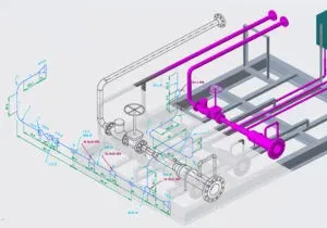
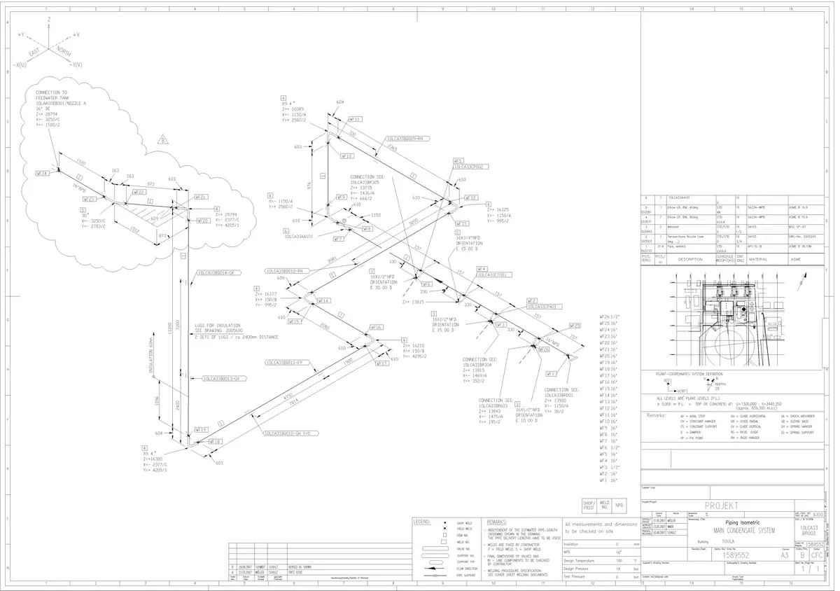
 Example of Isometric DWG
Step 1: Read the title block. The title block contains key information before you even look at the drawing: line number, pipe class, design pressure and temperature, fluid service, insulation type, painting/coating code, and the from/to equipment references. Missing any of these details means you are working blind.
Step 2: Orient yourself. Find the North arrow (usually in the upper right corner). Identify which direction is “up” in the plant. The three isometric axes appear at 30 degrees and 90 degrees from horizontal. The north arrow tells you how the drawing relates to the actual plant orientation.
Step 3: Identify the main run. The primary line (thickest lines) shows the main pipe routing. Branch connections come off this. Trace the line from the starting terminal point (equipment nozzle, tie-in, or continuation from another iso) to the ending terminal point.
Step 4: Decode the line designation. Typically shown as: 2"-P-1001-A1A-CS
- 2” = nominal pipe size
- P = process (fluid service code)
- 1001 = line number
- A1A = pipe class
- CS = carbon steel
Step 5: Read the fittings and components. Standard isometric symbols apply:
- Circles with lines = flanges
- Perpendicular lines = welds
- Angled segments = elbows (90-degree or 45-degree)
- T-shapes = tees
- Trapezoids = concentric or eccentric reducers
- Valve symbols with tags = valves (gate, globe, ball, check, etc.)
Step 6: Check dimensions and elevations. All dimensions are called out explicitly (never try to scale from the drawing). Key dimensions include:
- Face-to-face dimensions between flanges
- Centerline elevations (e.g., EL +5000 mm)
- Coordinates (northing, easting) at key nodes
- Weld-to-weld measurements
- Offsets and slopes (with gradient callouts)
Step 7: Review the BOM. The Bill of Materials lists every component needed to build that line. Cross-reference against the drawing to verify completeness. Each BOM entry includes item number, description, size, material specification, standard, and quantity.
Step 8: Identify welds. Each weld joint has a unique number. Shop welds (SW) are completed during spool fabrication in controlled conditions; field welds (FW) are completed during site erection. The weld summary may also specify NDE requirements (RT, UT, MT, PT) per the project inspection plan.
Step 9: Check notes and special requirements. Look for PWHT (post-weld heat treatment) flags, spring support locations, slope requirements, cold spring instructions, and any hold points for QC inspection.
Step 10: Coordinate with the P&ID. The isometric should match the P&ID in terms of components and connections. Every valve, instrument connection, drain, vent, and branch shown on the P&ID must appear on the isometric. Any discrepancy needs resolution before fabrication.
Common Isometric Symbols and Conventions
Isometric drawings use a standardized set of symbols recognized across the piping industry. While minor variations exist between companies and software tools, the core symbols are universal.
Pipe and Fitting Symbols
| Symbol | Component | Notes |
|---|---|---|
| Single line | Pipe run | Standard representation for all pipe sizes |
| 90-degree bend | 90-degree elbow | Long radius (LR) is default; short radius (SR) annotated separately |
| 45-degree bend | 45-degree elbow | Annotated with “45” to distinguish from 90-degree |
| T-intersection | Tee | Equal tee or reducing tee (sizes noted) |
| Trapezoid (symmetric) | Concentric reducer | Large end to small end shown by width change |
| Trapezoid (offset) | Eccentric reducer | Flat side noted (FOT = flat on top, FOB = flat on bottom) |
| Triangle at pipe end | Welding neck flange | Rating and face type annotated (e.g., 150# RF) |
| Circle at pipe end | Slip-on flange | Distinguished from WN by symbol shape |
| Perpendicular tick marks | Butt weld | ”FW” for field weld, “SW” for shop weld |
| ”X” on the line | Socket weld | Common on small-bore connections (NPS 2 and below) |
| Filled circle | Threaded connection | Small-bore instrument and utility connections |
| Cap symbol | Pipe cap | Flat or dished end closure |
Valve Symbols on Isometrics
| Symbol | Valve Type | Typical Application |
|---|---|---|
| Two triangles, points touching | Gate valve | On/off isolation |
| Two triangles with disc detail | Globe valve | Flow regulation |
| Circle with line | Ball valve | Quick shut-off |
| Single triangle with hinge | Check valve | Backflow prevention |
| Two triangles with butterfly | Butterfly valve | Large-diameter isolation |
Annotation Conventions
| Annotation | Meaning |
|---|---|
| North arrow | Plant orientation reference; matches the plot plan |
| EL +5000 | Elevation of pipe centerline (in mm or ft from datum) |
| N 1250, E 3400 | Plant coordinates at a reference point |
| BOP / TOP / CL | Bottom of pipe, top of pipe, centerline |
| SLOPE 1:100 | Pipe gradient (direction indicated by arrow) |
| MATCH LINE ISO-xxx | Continuation reference to another isometric drawing |
| FW / SW | Field weld / shop weld |
| PWHT | Post-weld heat treatment required at that joint |
| CS (cold spring) | Intentional gap or overlap for thermal expansion compensation |
Information Contained in an Isometric
A complete piping isometric is more than just a routing diagram. It is a self-contained construction package containing several categories of data.
Title Block Information
| Field | Content |
|---|---|
| Line number | Unique pipeline identifier (e.g., 6”-P-1001-B1A-I) |
| Pipe class | Material and rating designation per project specification |
| Design pressure/temperature | Operating envelope for the line |
| Fluid service | Process fluid (e.g., crude oil, cooling water, steam) |
| Insulation type and thickness | Heat conservation, personnel protection, or anti-condensation |
| Paint/coating system | Corrosion protection specification |
| From/To | Terminal equipment or tie-in references |
| Test pressure | Hydrotest or pneumatic test value |
| Revision history | Drawing revision number, date, and description of changes |
Bill of Materials (BOM)
The BOM is typically located at the bottom or right side of the isometric and lists every component:
| BOM Column | Example |
|---|---|
| Item number | 1, 2, 3… |
| Description | 6” LR 90-deg elbow, BW, Sch 40 |
| Material specification | ASTM A234 WPB |
| Size | 6” (DN 150) |
| Schedule/class | Sch 40 / Class 150 |
| Standard | ASME B16.9 |
| Quantity | 4 EA |
Weld Summary
Many isometrics include a weld summary table that lists:
- Weld number (unique identifier)
- Weld type (butt weld, socket weld, fillet weld)
- Size (pipe diameter at the joint)
- Shop or field designation
- NDE requirements (percentage RT, UT, MT, PT)
- PWHT requirement (yes/no)
Drawing Notes
Standard notes on isometrics typically cover:
- All dimensions in millimeters (or inches, per project standard)
- All elevations referenced to a specific datum (e.g., plant zero or mean sea level)
- Gasket and bolt specifications per the pipe class
- Welding procedure references (WPS numbers)
- Painting and insulation applied after hydrotest
- “Do not scale” warning
Isometric vs P&ID vs GA Drawing
Three documents describe the same piping system in fundamentally different ways. Understanding what each shows (and what it leaves out) matters for any piping professional.
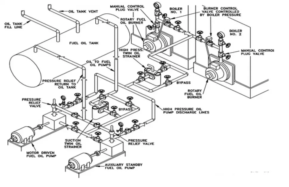
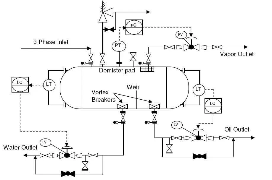 Example of P&ID diagram
| Aspect | Piping Isometric | P&ID | GA Drawing |
|---|---|---|---|
| Shows | Physical layout, dimensions, routing | Process logic, control loops, instruments | Equipment positions, overall dimensions, nozzle locations |
| Scale | Not to scale (dimensions called out) | Schematic (no spatial accuracy) | Drawn to scale |
| Audience | Fabricators, pipefitters, construction | Process engineers, operators, maintenance | All disciplines for coordination |
| Purpose | ”How to build it" | "How it works" | "Where everything sits” |
| Includes | Weld locations, support points, elevations | Valve failure positions, control schemes | Nozzle orientations, support details, weights |
| Missing | Process data, operating conditions | Actual dimensions, routing details | Individual piping routing, weld details |
| Level of detail | Very high (component level) | Medium (functional level) | Medium (interface level) |
Both the P&ID and isometric must reconcile. Every valve on the P&ID needs to appear on an isometric; every instrument connection needs piping detail. Discrepancies create field problems.
Orthographic vs. Isometric Drawings
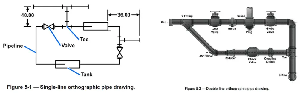 Orthographic view: single and double line (source: Frank Minnella)
| Type | View | Scale | Best For |
|---|---|---|---|
| Orthographic | Multiple 2D views (plan, elevation, section) | Drawn to scale | Precise measurements, detailed fabrication |
| Isometric | Single pseudo-3D view | Not to scale | Visualizing routing, understanding spatial relationships |
Orthographic drawings answer “what are the exact dimensions?” Isometric drawings answer “how does it all fit together?” Most piping projects use both: orthographics for equipment layouts and structural details, isometrics for piping systems.
Plan, Elevation, and Isometric Views
 Piping isometric drawing example
| View Type | Perspective | Shows | Used For |
|---|---|---|---|
| Plan | Top-down (bird’s eye) | Horizontal routing, equipment locations | Layout coordination, plot plans |
| Elevation | Side view (north, south, east, west) | Vertical routing, heights, levels | Multi-story coordination, rack design |
| Isometric | 3D on 2D (30-degree angles) | Complete routing in one view | Fabrication, BOMs, installation |
A complete piping package uses all three views. Plans show where pipes go horizontally; elevations show heights; isometrics show how individual lines are constructed.

Fabrication Isometrics vs Design Isometrics
Not all isometrics are the same. The industry distinguishes between two major categories, each serving a different purpose in the project lifecycle.
Design Isometric (Engineering Isometric)
The design isometric shows the complete pipeline from terminal point to terminal point. It is produced during detailed engineering and contains:
- Full routing with all components
- Overall dimensions and coordinates
- Complete BOM for the entire line
- All weld locations (shop and field)
- Pipe support locations (type and tag number)
- Instrument and branch connections
Design isometrics are issued in stages: IFR (Issued for Review), IFA (Issued for Approval), and finally IFC (Issued for Construction). Only IFC-status isometrics should be released to the fabrication shop.
Fabrication Isometric (Spool Drawing)
A fabrication isometric breaks the full pipeline into individual spool pieces (transportable, pre-fabricated pipe assemblies). Each spool drawing includes:
- Detailed cut lengths for each pipe piece
- Weld preparation details (bevel angles, root gaps)
- Precise fit-up dimensions (face-to-face, center-to-face)
- Spool weight for lifting and transport planning
- Match marks for field alignment
- Spool-specific BOM
| Aspect | Design Isometric | Fabrication Isometric |
|---|---|---|
| Scope | Entire pipeline | Single transportable spool |
| Issued to | Engineering, procurement, construction | Pipe fabrication shop |
| Dimensions | Overall routing and key coordinates | All cut lengths and fit-up details |
| BOM | Full line material list | Spool-specific material list |
| Weld detail | Location and numbering | Preparation, procedure, NDE requirements |
Software Used for Piping Isometrics
Modern EPC projects generate isometrics automatically from 3D piping models. The leading software platforms are:
| Software | Developer | Isometric Module | Key Strength |
|---|---|---|---|
| AVEVA E3D (formerly PDMS) | AVEVA | AVEVA Isodraft | Dominant in European and Middle Eastern EPCs |
| Smart 3D / SP3D (formerly PDS) | Hexagon PPM | SmartPlant Isometrics (SPI / I-Configure) | Strong in North American owner-operators |
| AutoCAD Plant 3D | Autodesk | Built-in Isometric Generator | Popular for smaller projects and brownfield work |
| IsoGen | AVEVA (standalone) | N/A (is the iso engine) | The underlying engine used by many platforms |
| Caesar II | Hexagon PPM | N/A (stress analysis) | Verifies that the routed isometric is structurally sound |
Auto-Generation Workflow
The typical workflow for generating isometrics from a 3D model:
- Piping designer models the line in the 3D environment per the P&ID and pipe class specification
- Clash detection is run to verify no interference with structural, electrical, or other disciplines
- Design review (model review walkthrough) is completed and comments resolved
- Isometric extraction generates the drawing automatically from the model data
- Quality check by a checker or lead engineer verifies accuracy
- Stress analysis using Caesar II confirms flexibility and support loads
- Issue for construction after all reviews and approvals are complete
How Isometrics Are Used in Construction and Fabrication
Piping isometrics are the primary working documents for both shop fabrication and field installation. Their role extends throughout the construction phase.
In the Fabrication Shop
- Material allocation: The BOM is used to draw materials from the warehouse (pipe, fittings, flanges)
- Cutting and beveling: Pipe lengths are cut per the spool drawing dimensions
- Fit-up: Components are assembled per the isometric routing and tacked in position
- Welding: Shop welds are completed per the applicable WPS (welding procedure specification)
- QC inspection: Weld numbers are tracked against the weld map; NDE is performed per the inspection and test plan
- Marking and shipping: Spools are tagged with spool numbers matching the isometric
In the Field
- Spool erection: Pre-fabricated spools are lifted into position using coordinates from the isometric
- Field welding: Remaining FW joints are completed to connect spools together and to equipment nozzles
- Support installation: Pipe supports shown on the isometric are installed at the correct locations
- Dimensional verification: Field engineers verify installed dimensions against the isometric
- Redline markup: Any field changes are recorded on the isometric for as-built documentation
- Hydrotest: Test boundaries shown on the isometric define the scope of each pressure test
Quality Checks on Piping Isometrics
Before an isometric is issued for construction, it should pass through a structured quality review. Common checks include:
| Check | What to Verify |
|---|---|
| P&ID reconciliation | Every component on the P&ID appears on the isometric |
| Pipe class compliance | All components match the pipe class specification (correct ratings, material grades, end connections) |
| Dimensional accuracy | Coordinates and elevations match the 3D model; dimensions are consistent |
| BOM completeness | Every component on the drawing is in the BOM; quantities match |
| Weld numbering | All welds are numbered; shop/field designation is correct |
| Slope and drainage | Sloped lines have correct gradient and direction |
| Support locations | All supports shown match the stress analysis output |
| Instrument connections | All instrument taps, tapping points, and branch connections from the P&ID are included |
| Continuation references | Match lines reference the correct adjacent isometric drawing numbers |
| Spec breaks | Changes in pipe class (spec breaks) are correctly shown with the right transition components |
Common Errors in Isometric Drawings
Even experienced piping designers make mistakes. Knowing the common errors helps checkers and field engineers catch problems before they become expensive.
| Error | Impact | Prevention |
|---|---|---|
| Missing components | Field shortages, construction delays | Rigorous P&ID reconciliation |
| Wrong dimensions | Spools don’t fit, rework required | Verify against 3D model coordinates |
| Incorrect pipe class | Wrong material installed | Cross-check line designation vs pipe class database |
| BOM mismatch | Extra or missing material ordered | Count components on drawing vs BOM |
| Wrong weld type | Socket weld shown instead of butt weld | Verify against pipe class connection table |
| Missing slope | Line doesn’t drain, liquid accumulates | Check P&ID for drainage requirements |
| Elevation errors | Clashes with structural steel, equipment | Verify against 3D model and structural drawings |
| Outdated revision | Fabrication from superseded drawing | Strict document control procedures |
| Missing gaskets/bolts | Cannot complete flange assembly | Auto-generate gaskets and bolts from pipe class |
| Incorrect flow direction | Check valves and some instruments installed backward | Verify flow arrows against P&ID |
Challenges in Making Isometrics
Creating accurate isometrics is not trivial. Common challenges include:
| Challenge | Reality |
|---|---|
| System complexity | A single line can have dozens of fittings, branches, and instrument connections |
| Multi-discipline coordination | Piping must avoid structural, electrical, and HVAC; everyone’s routing matters |
| Data quality | Bad input data = bad isometrics. “Garbage in, garbage out” applies here |
| Software proficiency | 3D modeling tools (Plant 3D, SP3D, E3D) have steep learning curves |
| Standardization | Every company uses slightly different symbols and conventions |
| Code compliance | ASME B31.1, B31.3, client specs; someone needs to know the rules |
| Brownfield constraints | Existing plant conditions (undocumented modifications, missing as-builts) make accurate isometrics harder |
The best isometric drafters combine software skills with field experience. They know what actually gets built, not just what looks good on paper.
Standards and Conventions
Piping isometric drawing standards are not governed by a single universal code. Instead, they follow a combination of industry practices, company standards, and client specifications.
| Standard/Convention | Scope |
|---|---|
| PIP (Process Industry Practices) | PIP PIC001 defines standard piping isometric drawing requirements widely used in North American refineries and petrochemical plants |
| ASME Y14.5 | Dimensioning and tolerancing standard (general, not piping-specific) |
| ISO 6412 | International standard for simplified representation of pipelines in isometric drawings |
| Client-specific standards | Major operators (Aramco, Shell, ExxonMobil, TotalEnergies) each have detailed piping drawing requirements in their engineering standards |
| Contractor standards | Large EPCs (Bechtel, Fluor, Technip, Saipem, Wood) maintain their own isometric drawing procedures |
In practice, the project Design Basis or Piping Design Criteria document specifies which conventions apply. This includes:
- Dimensioning units (mm vs inches)
- Elevation datum reference
- North arrow position and style
- BOM format and content
- Weld numbering scheme
- Revision control procedures
- Line designation coding convention
Hatches in Isometric Drawings
Hatching patterns indicate materials or conditions without lengthy text annotations.
 Hatches
| Pattern | Typical Use |
|---|---|
| Solid fill | Structural elements, equipment |
| Crosshatch | Specific materials (concrete, insulation) |
| Dotted/dashed | Hidden components, future work |
| Diagonal lines | Insulation thickness |
Key rules for hatching:
- Be consistent: same material = same hatch throughout the project
- Include a legend: never assume the reader knows your conventions
- Don’t over-hatch: cluttered drawings are unreadable
- Match project standards: client specs often dictate hatch patterns
Types of Isometric Views
For piping applications, true isometric is standard. Other projection types exist but are rarely used:
| View Type | Description | Piping Use |
|---|---|---|
| True Isometric | All three axes at 120 degrees, equal scaling | Standard for piping isometrics |
| Dimetric | Two axes equal, one different | Rarely used |
| Trimetric | All three axes different | Rarely used |
| Oblique | One face shown flat, depth at 45 degrees | Sometimes for simple sketches |
When someone says “isometric” in piping, they mean true isometric. The 30-degree angles from horizontal are universal in the industry.
Frequently Asked Questions
What is a piping isometric drawing?
A piping isometric drawing (or "iso") is a 3D representation of a piping system drawn on a 2D sheet using isometric projection, where the three spatial axes appear at 120-degree angles. It shows every component of a pipeline (pipe runs, fittings, valves, flanges, weld locations, dimensions, and elevations) in a single view. Unlike P&IDs, which show process logic, isometrics are construction documents that fabricators and pipefitters use to build the system. They are not drawn to scale; all dimensions are called out numerically.
What is the difference between a piping isometric and a P&ID?
A P&ID (Piping and Instrumentation Diagram) shows the process logic, control loops, instruments, and functional relationships of a piping system; it answers "how it works." A piping isometric shows the physical layout, routing, dimensions, fittings, weld locations, and materials needed to fabricate and install a specific pipeline; it answers "how to build it." Both documents must reconcile: every valve, instrument connection, drain, and vent on the P&ID must appear on the corresponding isometric drawing.
What software is used to create piping isometric drawings?
The most widely used platforms are AVEVA E3D (formerly PDMS) with AVEVA Isodraft, Hexagon Smart 3D (SP3D) with SmartPlant Isometrics (SPI/I-Configure), and Autodesk AutoCAD Plant 3D with its built-in isometric generator. These 3D modeling tools auto-generate isometrics from the piping model. Caesar II by Hexagon is used alongside for pipe stress analysis to verify that the routed design is structurally sound. For smaller projects or field modifications, isometrics may be drawn manually in 2D AutoCAD.
What is the difference between a fabrication isometric and a design isometric?
A design isometric (engineering isometric) shows the full pipeline routing from terminal point to terminal point, including all components, overall dimensions, coordinates, and the complete bill of materials. A fabrication isometric (spool drawing) breaks that pipeline into individual transportable spool pieces, with detailed cut lengths, weld preparation details, fit-up dimensions, spool weight, and shop-specific fabrication notes. Design isometrics are issued for engineering review and procurement; fabrication isometrics are issued directly to the pipe fabrication shop.
How do you read a piping isometric drawing?
Start by reading the title block to identify the line number, pipe class, design conditions, and service. Then orient yourself using the north arrow and coordinate axes. Trace the main pipe run from the starting equipment nozzle to the termination point, noting every fitting, valve, and branch connection. Check all dimensions and elevations (never scale from the drawing). Review the BOM (bill of materials) and cross-reference every component against the drawing. Identify all weld locations (shop vs field). Finally, reconcile the isometric against the P&ID to make sure nothing is missing.
Leave a Comment
Have a question or feedback? Send us a message.