Fillet Welds in Piping: Sizing, Types, Standards & Inspection
Fillet Weld
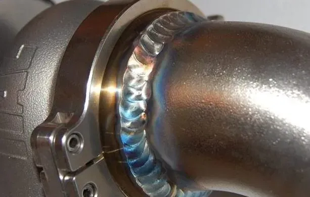
What Is a Fillet Weld?
A fillet weld joins two metal surfaces that meet at an angle (typically 90 degrees) by depositing weld metal to form a roughly triangular cross-section. Unlike a butt weld, which connects two pipe ends in the same plane, a fillet weld works where one surface sits against another: a pipe inserted into a socket, a flange slipped over a pipe, or a branch connection sitting on a header.
In piping, fillet welds are the standard way to attach socket weld fittings (elbows, tees, couplings, reducers) and slip-on flanges to pipe. They are also used on branch connections like sockolets and weldolets where the branch meets the header.
 fillet weld
Compared to butt welds, fillet welds require no bevel preparation and less fit-up precision. The trade-off is that they cannot be radiographically inspected. You can’t shoot an RT on a fillet weld, so inspection relies on visual, MT (magnetic particle), or PT (liquid penetrant) methods.
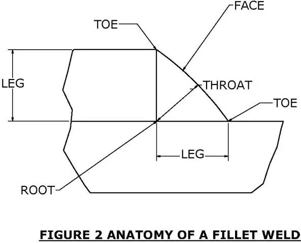
Fillet Weld Anatomy
Every fillet weld has the same basic geometry, and understanding it matters because the weld’s structural capacity depends on these dimensions:
 Fillet Welds Anatomy
- Legs: the two sides of the triangle, measured along each surface from the root. In most piping applications, both legs are equal. When they’re not, both dimensions must be specified (e.g., 6mm x 8mm).
- Throat: the shortest distance from the root to the face of the weld. This is the dimension that determines the weld’s load-carrying capacity. For equal-leg fillets, the theoretical throat = leg size x 0.707.
- Root: the deepest point where the two surfaces meet, inside the weld. Poor root fusion is a common defect.
- Toes: the points where the weld face meets the base metal on either side. Undercut and fatigue cracks typically start at the toes.
- Face: the exposed outer surface of the weld, which can be flat, convex, or concave depending on the specification and welding technique.
When a designer specifies a fillet weld size, they mean the leg length. A “6mm fillet” has 6mm legs and an approximate throat of 4.2mm (6 x 0.707). The throat is what resists shear, so it’s the number that goes into strength calculations.
Fillet Weld Sizing Rules
Correct fillet weld sizing is essential for joint integrity. Undersized welds fail under load; oversized welds waste material, increase distortion, and raise residual stress without adding proportional strength.
Throat and Leg Calculations
For an equal-leg fillet weld, the relationship between leg size (L) and theoretical throat (T) is:
T = L x 0.707 (or L x cos 45 degrees)
The effective throat is the minimum distance from the root to the weld face, minus any convexity. For concave fillets, the effective throat is less than the theoretical throat, which means a concave fillet must have larger legs to carry the same load as a flat fillet.
The actual throat includes root penetration beyond the theoretical root. Some welding processes (like GMAW with spray transfer) consistently produce deeper root penetration, which increases the actual throat beyond the theoretical value. However, codes generally require that the theoretical throat meet minimum requirements, and excess penetration is considered a bonus.
Sizing Per ASME B31.3
ASME B31.3 specifies that the minimum fillet weld leg size for socket weld connections must be at least 1.09 times the nominal pipe wall thickness (cx = 1.09 x tn). This formula makes sure the throat dimension provides adequate shear strength relative to the pipe wall.
For slip-on flanges, the same 1.09x rule applies to both the hub-side (external) and bore-side (internal) fillet welds.
Sizing Per AWS D1.1
While AWS D1.1 applies primarily to structural welding rather than pressure piping, it is relevant for pipe support attachments, structural steel connections to piping, and non-pressure welds in piping facilities. AWS D1.1 Table 5.8 specifies minimum fillet weld sizes based on the thicker part being joined:
| Base Metal Thickness (mm) | Minimum Fillet Leg Size (mm) |
|---|---|
| Up to 6mm | 3mm |
| 6mm to 13mm | 5mm |
| 13mm to 19mm | 6mm |
| Over 19mm | 8mm |
These minimums prevent rapid cooling and hydrogen cracking in the HAZ. For piping pressure joints, always use the ASME B31.3 sizing rules instead.
Key Takeaway: The throat dimension, not the leg size, determines fillet weld strength. For equal-leg fillets, throat = 0.707 x leg. Always size fillet welds per the applicable code: ASME B31.3 (1.09 x tn) for pressure piping, AWS D1.1 for structural attachments.
Types of Fillet Weld Joints
Fillet welds are used on three basic joint configurations. In piping work, the tee joint is by far the most common, but it helps to understand all three.
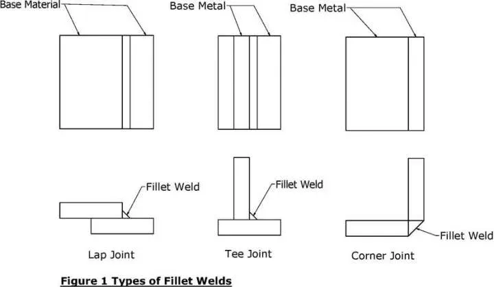
Tee Joint
The most relevant joint type for piping. One member sits perpendicular against another, forming a “T” shape. Every socket weld connection, every slip-on flange, and every branch fitting attachment is essentially a tee joint. The fillet weld fills the corner where the two surfaces meet. Depending on design loads and code requirements, the weld may be applied on one side or both sides.
Lap Joint
Two overlapping pieces welded along the edge of the overlap. Less common in process piping, but used in structural supports, pipe hangers, and saddle-type connections. The fillet runs along the edge of the overlapping plate.
Corner Joint
Two pieces meet at their edges to form a corner. Found mainly in duct work, box structures, and equipment fabrication rather than in pressure piping. Fillet welds fill the inside or outside corner.
Fillet Weld vs Butt Weld
The choice between fillet and butt weld connections isn’t arbitrary; it depends on pipe size, service conditions, and code requirements.
| Aspect | Fillet Weld | Butt Weld |
|---|---|---|
| Pipe size range | Typically NPS 1/2” to 2” (small bore) | NPS 2” and above (large bore) |
| Joint prep | No bevel needed | Requires bevel preparation |
| Fit-up | More forgiving | Tight tolerances required |
| Connection types | Socket weld fittings, slip-on flanges | Butt weld fittings, weld neck flanges |
| Radiographic testing | Not possible (geometry prevents RT) | Full RT/UT possible |
| Fatigue resistance | Lower (stress concentration at toes) | Higher (smooth profile when ground flush) |
| Corrosion traps | Socket creates crevice at pipe end | No crevice |
| Strength | Adequate for small bore service | Full-strength joint |
| Cost per joint | Lower (no bevel, simpler fit-up) | Higher (bevel prep, tighter tolerances) |
| Weld volume | Less filler metal required | More filler metal for thick walls |
| Code examination | VT, PT, MT only | VT, RT, UT, PT, MT all applicable |
In practice, most process piping specs draw the line at NPS 2”: socket weld with fillet welds below 2”, butt weld above 2”. Some specs set it at 1-1/2” for critical services. For severely cyclic, corrosive, or high-purity services (like hydrogen, oxygen, or pharmaceutical piping), butt weld connections may be required even on small bore lines to avoid the crevice geometry and improve inspectability.
Fillet Welds on Socket Weld Fittings
This is where fillet welds are most critical in piping systems. Socket weld fittings (elbows, tees, couplings, reducers, caps per ASME B16.11) have a recessed bore (the “socket”) that the pipe slides into. A circumferential fillet weld around the outside of the joint seals and secures the connection.
The 1/16” Expansion Gap
This is arguably the single most important rule for socket weld fillet welds: after inserting the pipe fully into the socket, pull it back approximately 1/16” (1.6mm) before tacking.
The reason is thermal expansion. If the pipe bottoms out in the socket and is welded tight, thermal cycling during operation will force the pipe to push against the socket bottom. That creates axial stresses right at the weld root, and over time (sometimes only a few hundred cycles) the weld cracks. It’s one of the most common failure modes in small-bore piping.
The practical procedure:
- Insert the pipe fully into the socket until it bottoms out.
- Mark the pipe at the face of the fitting with a soapstone or marker.
- Pull the pipe back approximately 1/16” (1.6mm) from the bottom.
- Tack weld in position.
- Complete the fillet weld.
Some fabrication shops use a spacer ring or a piece of wire of the right gauge to set the gap consistently.
Minimum Weld Size
Per ASME B31.3 (Process Piping), the minimum fillet weld leg size for socket weld connections must be at least 1.09 times the nominal pipe wall thickness (tn). Here are some practical values:
| Pipe Size (NPS) | Schedule | Wall Thickness (mm) | Min. Fillet Weld Leg (mm) |
|---|---|---|---|
| 1/2” | 80 (3000#) | 3.73 | 4.1 |
| 3/4” | 80 (3000#) | 3.91 | 4.3 |
| 1” | 80 (3000#) | 4.55 | 5.0 |
| 1-1/2” | 80 (3000#) | 5.08 | 5.5 |
| 2” | 80 (3000#) | 5.54 | 6.0 |
| 1/2” | 160 (6000#) | 4.75 | 5.2 |
| 3/4” | 160 (6000#) | 5.56 | 6.1 |
| 1” | 160 (6000#) | 6.35 | 6.9 |
These are minimums. Many project specifications call for larger fillets, and the welding procedure may produce a naturally larger weld.
Number of Passes
ASME codes don’t prescribe a minimum number of passes, but good practice (and many project specs) require at least two passes for socket weld fillets. There’s a practical reason: a single-pass fillet weld leaves a coarse grain structure in the heat-affected zone, and the weld toe acts as a natural stress concentrator. The second pass tempers the HAZ from the first pass and often smooths the toe profile, which significantly improves fatigue life.
For cyclic service (per ASME B31.3, Chapter IX), two passes should be considered mandatory.
Fillet Welds on Slip-On Flanges
Slip-on flanges require two fillet welds: one on the outside (hub face) and one on the inside (bore side). This double-fillet arrangement is a code requirement, not optional.
The outside fillet weld is the primary structural weld. The inside fillet (sometimes called the “seal weld” though it does more than seal) prevents crevice corrosion between the pipe OD and the flange bore, and adds structural strength.
Per ASME B31.3, the pipe should extend through the flange face by an amount equal to the wall thickness plus approximately 3mm (1/8”), then be fillet welded on both sides. The minimum fillet size for both welds follows the same 1.09x rule as socket weld connections.
Slip-on flanges are rated at about two-thirds the strength of weld neck flanges because of this fillet weld connection. For high-pressure or high-temperature service (above Class 300 or above 400F/200C), most engineering specs switch to weld neck flanges with butt welds.
Seal Welds vs Structural Fillet Welds
In piping work, the term “seal weld” gets used frequently, but it means something specific and different from a standard structural fillet weld.
A seal weld is a fillet weld applied over a threaded connection solely to prevent leakage through the thread spiral path. It is not designed to carry structural load; the threads still handle the mechanical forces. Seal welds are common on threaded instrument connections, drain and vent connections, and small-bore threaded fittings in services where even minor thread leakage is unacceptable (toxic, flammable, or high-pressure fluids).
A structural fillet weld is designed and sized to carry the full mechanical load of the joint. Socket weld connections and slip-on flange attachments use structural fillet welds. These welds are sized per ASME B31.3 (1.09 x tn), require qualified welding procedures (WPS per ASME IX), and must meet the full range of NDE requirements specified by the piping class.
| Characteristic | Seal Weld | Structural Fillet Weld |
|---|---|---|
| Primary purpose | Leak prevention | Load bearing + leak prevention |
| Applied over | Threaded connections | Socket weld / slip-on joints |
| Sizing requirement | No minimum code size | 1.09 x tn per ASME B31.3 |
| Load-bearing design | No (threads carry load) | Yes (weld carries full load) |
| WPS qualification | Required per ASME IX | Required per ASME IX |
| NDE requirements | VT minimum; PT/MT per spec | VT, PT/MT per piping class |
| PWHT | Per material requirements | Per material requirements |
Fillet Weld Symbols and Drawing Conventions
Reading welding symbols is required for anyone working with piping isometrics and fabrication drawings. The fillet weld symbol follows the AWS A2.4 / ISO 2553 system.
The basic symbol consists of a reference line, an arrow line, the tail, Weld Procedure Specification (WPS) information, and the fillet weld symbol including leg size.
Symbol Components
| Component | Description |
|---|---|
| Reference line | Always drawn horizontally; contains weld type information; connects arrow line and tail |
| Arrow line | Points to the weld location on the component |
| Arrow side | Underside of the reference line; weld symbols here are placed on the arrow side of components |
| Other side | Weld symbols above the reference line are placed on the side opposite the arrow |
| Tail | Optional element containing WPS information, procedures, and parameters |
| Fillet symbol | Represented as a triangle; leg size placed to the left of the symbol |
Most fillet welds in piping have equal legs. When legs are unequal, both dimensions are noted (e.g., 6 x 8). For socket weld connections, the symbol typically appears with the triangle on the arrow side, with the leg size shown to the left.
Special Indicators
A circle at the juncture of the reference line and arrow line means “weld all around,” so the fillet goes 360 degrees around the joint. This is standard for all socket weld and slip-on flange fillet welds in piping.
A darkened flag at the same juncture means the weld is to be performed in the field (as opposed to shop fabrication).
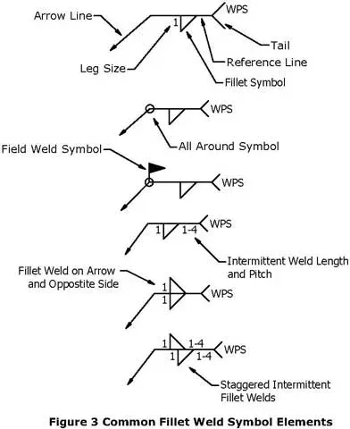
Fillet welds don’t have to be continuous. For non-pressure applications (structural attachments, pipe supports), intermittent fillet welds save time and reduce distortion. The length and pitch are shown to the right of the symbol (e.g., “50-100” means 50mm weld length at 100mm center-to-center spacing). In pressure piping, though, fillet welds are almost always continuous.
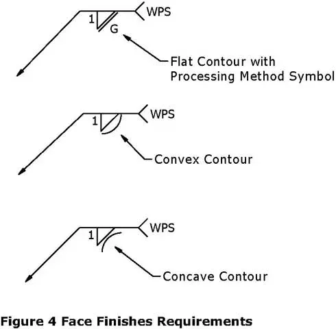
The weld face profile can be specified as flat, convex, or concave. If finishing is required, it’s indicated by a letter: C (chipped), G (ground), H (hammered), M (machined), R (rolled), or P (peened).
AWS A2.4 vs ISO 2553
Most piping projects in North America and the Middle East use the AWS A2.4 convention, where the arrow-side symbol is placed below the reference line and the other-side symbol above it. ISO 2553 (common in Europe) reverses this convention. Always confirm which standard applies to the project before interpreting weld symbols on drawings.
Fillet Weld Applications in Piping: Comparison Table
The following table summarizes where fillet welds are used in piping systems, along with the applicable standards and typical NDE requirements.
| Application | Joint Type | Weld Configuration | Applicable Standard | Typical NDE |
|---|---|---|---|---|
| Socket weld elbows, tees, couplings | Tee joint | Single circumferential fillet | ASME B31.3, B16.11 | VT + PT or MT |
| Slip-on flanges (hub side) | Tee joint | External circumferential fillet | ASME B31.3, B16.5 | VT + PT or MT |
| Slip-on flanges (bore side) | Tee joint | Internal circumferential fillet | ASME B31.3, B16.5 | VT (PT if accessible) |
| Sockolets / weldolets on headers | Tee joint | Circumferential fillet or partial-pen + fillet | ASME B31.3, MSS SP-97 | VT + PT or MT |
| Seal welds on threaded connections | Tee joint | Single fillet over threads | ASME B31.3 | VT minimum |
| Pipe support attachments | Tee / lap | Intermittent or continuous fillet | AWS D1.1 | VT |
| Reinforcement pads on branches | Lap joint | Circumferential fillet at pad edge | ASME B31.3 | VT + PT or MT |
| Trunnion supports on pipe | Tee joint | Continuous fillet around trunnion base | ASME B31.3 / project spec | VT + MT |
Common Fillet Weld Defects
Fillet welds on small-bore piping might seem straightforward, but they account for a disproportionate share of weld repairs and in-service failures. Here are the defects that come up most often:
Undercut occurs when the arc melts a groove into the base metal at the weld toe without filling it. It reduces the effective wall thickness and creates a sharp notch, exactly where fatigue cracks like to start. Undercut deeper than 0.8mm (1/32”) or 10% of base metal thickness is typically rejectable per ASME B31.3. High amperage and excessive weave width are the usual causes.
Lack of fusion at the root means the weld metal didn’t fully bond to both base metal surfaces at the deepest part of the joint. This is hard to detect since you can’t radiograph a fillet weld, and it only shows up on destructive examination or when the joint leaks. Low heat input and improper electrode angle are common causes.
Porosity (gas pockets trapped in the weld metal) is often caused by moisture, contaminated base metal, or inadequate gas shielding. A few scattered pores are usually acceptable; clustered or linear porosity is not.
Cracking in fillet welds falls into two categories. Hot cracking happens during solidification (usually in stainless steels with high sulfur content). Cold cracking (hydrogen-induced) shows up hours or days after welding, especially in carbon and alloy steel fittings when preheat was skipped or hydrogen control was poor.
Excessive convexity makes the weld look “fat” and actually hurts fatigue performance by concentrating stress at the toes. A slightly concave or flat profile is better for fatigue resistance.
Insufficient leg size is caught by gauging with a fillet weld gauge. An undersized fillet means the throat is too thin, and the joint’s load capacity is below design. This is a rejectable condition that requires adding another pass.
Overlap (cold lap) occurs when weld metal flows onto the base metal surface without fusing to it. The overlapping metal creates a notch effect similar to undercut and can mask lack-of-fusion beneath. It is caused by excessive weld pool size, insufficient travel speed, or incorrect electrode angle.
Inspection and NDE Requirements
Since fillet welds can’t be radiographed (the joint geometry makes RT impractical), inspection relies on other methods:
Visual examination (VT) is mandatory for all fillet welds per ASME B31.3. The inspector checks for complete fusion at the toes, correct weld size (using a fillet weld gauge), acceptable profile, absence of cracks, and that any undercut is within limits. A trained eye catches most problems.
Liquid penetrant testing (PT) reveals surface-breaking defects that visual inspection might miss: fine cracks, pinhole porosity, and tight lack-of-fusion at the toes. It’s standard practice for stainless steel and alloy fillet welds and commonly specified for all fillet welds in critical services.
Magnetic particle testing (MT) does the same job as PT but works only on ferromagnetic materials (carbon steel, low-alloy steel). It’s faster than PT and slightly more sensitive for subsurface defects near the surface. Many specs call for MT on carbon steel socket welds and PT on stainless.
Ultrasonic testing (UT) is not commonly applied to small-bore fillet welds due to geometric limitations. However, specialized UT techniques with miniature angle-beam probes can assess fillet welds on larger connections (NPS 4” and above sockolets, reinforcement pads). Time-of-flight diffraction (TOFD) and phased array UT (PAUT) have expanded the capability for fillet weld inspection on critical joints.
Hardness testing may be required after welding alloy steel fittings (Cr-Mo grades like ASTM A182 F11, F22) to verify that the post-weld heat treatment was effective and the HAZ hardness is within limits (typically 248 HV max for sour service per NACE MR0175).
NDE Extent by Examination Class
ASME B31.3 Table 341.3.2 defines examination extent based on fluid service category:
| Examination Type | Normal Fluid Service | Category D Fluid Service | Category M (Lethal) | High-Pressure Piping |
|---|---|---|---|---|
| Visual (VT) | 100% | 100% | 100% | 100% |
| PT or MT | Per piping class (5-20% typical) | Not required | 100% | 100% |
| Hardness (alloy) | Per WPS/project spec | Per WPS | 100% | 100% |
Fillet Weld Pre-Heat and PWHT
Pre-heat and post-weld heat treatment (PWHT) requirements depend on the base material and wall thickness, not the weld type. But fillet welds on small-bore fittings often get overlooked in the field (“it’s just a small weld”), so the requirements bear repeating:
Carbon steel (A105 fittings, A106 pipe): preheat generally required above 19mm (3/4”) wall thickness per ASME B31.3 Table 330.1.1. Most socket weld piping falls below this threshold, but thick-wall 6000# fittings on NPS 3/4” to 1” pipe can be close. Check the WPS.
Cr-Mo alloy steel (A182 F11, F22 fittings): preheat is always required, typically 150-200C minimum. PWHT is also mandatory. Skipping PWHT on a chrome-moly socket weld is a code violation and will result in a hard, brittle HAZ that’s susceptible to hydrogen cracking and stress corrosion in sour environments.
Stainless steel (A182 F304, F316 fittings): generally no preheat and no PWHT. In fact, PWHT is normally prohibited for austenitic stainless to avoid sensitization. The exception is for specific corrosion environments where solution annealing or stabilization heat treatment is specified.
Duplex stainless steel (A182 F51, F53): no PWHT, but heat input must be carefully controlled (both minimum and maximum) to maintain the correct ferrite/austenite balance. Too little heat input and you get excessive ferrite; too much and you risk sigma phase.
Applicable Standards Reference
The following standards govern fillet weld design, fabrication, and inspection in piping systems:
| Standard | Scope | Key Fillet Weld Provisions |
|---|---|---|
| ASME B31.3 | Process Piping | Minimum fillet weld size (1.09 x tn), expansion gap, examination requirements, preheat/PWHT tables |
| ASME B31.1 | Power Piping | Similar fillet weld requirements for power plant piping systems |
| ASME B16.11 | Forged Fittings | Defines socket weld fitting dimensions (socket depth, bore, wall thickness) that determine weld geometry |
| ASME B16.5 | Pipe Flanges | Defines slip-on flange dimensions; dual fillet weld requirement |
| ASME Section IX | Welding Qualification | WPS and welder qualification rules for fillet welds (QW-462.4 specimen requirements) |
| AWS A2.4 | Welding Symbols | Standard symbols and conventions for specifying fillet welds on drawings |
| AWS D1.1 | Structural Welding (Steel) | Minimum fillet sizes for structural attachments, workmanship standards |
| ISO 2553 | Welding Symbols (International) | International equivalent of AWS A2.4; different arrow-side/other-side convention |
| NACE MR0175 / ISO 15156 | Sour Service | Maximum hardness limits (248 HV) for fillet welds in H2S-containing environments |
| ASME B31.3 Chapter IX | High-Cycle Fatigue | Additional requirements for fillet welds in severely cyclic service |
Frequently Asked Questions
What is the minimum fillet weld size for socket weld fittings per ASME B31.3?
Per ASME B31.3, the minimum fillet weld leg size for socket weld connections must be at least 1.09 times the nominal pipe wall thickness (cx = 1.09 x tn). For example, a 1-inch Schedule 80 pipe with a 4.55mm wall thickness requires a minimum fillet weld leg of 5.0mm. These are code minimums; many project specifications call for larger fillets, and the welding procedure may naturally produce a larger weld. Always verify the required size against the project piping class specification.
Why is a 1/16-inch gap required on socket weld fittings?
The 1/16 inch (1.6mm) expansion gap between the pipe end and the socket bottom prevents thermal stress cracking. Without this gap, thermal cycling during operation forces the pipe to push against the socket bottom, creating axial stresses at the weld root. Over time (sometimes only a few hundred cycles) this causes fatigue cracking. The gap is maintained by inserting the pipe fully, marking the position, pulling back 1/16 inch, and then tack welding. Some shops use spacer rings or wire gauges for consistent gap setting.
What is the difference between a fillet weld and a butt weld in piping?
A fillet weld joins two surfaces meeting at an angle (typically 90 degrees) and forms a triangular cross-section. It requires no bevel preparation and is used on socket weld fittings and slip-on flanges, typically for pipe sizes NPS 2 inches and below. A butt weld joins two pipe ends aligned in the same plane after bevel preparation, creating a full-penetration joint. Butt welds are used on butt weld fittings and weld neck flanges for NPS 2 inches and above. The key advantage of butt welds is that they allow full radiographic and ultrasonic inspection, while fillet welds can only be examined by surface methods (VT, PT, MT).
What is a seal weld and how does it differ from a structural fillet weld?
A seal weld is a fillet weld applied over a threaded connection solely to prevent leakage through the thread spiral path. It is not designed to carry structural load; the threads still handle the mechanical forces. A structural fillet weld, by contrast, is sized per ASME B31.3 (minimum 1.09 x tn) and designed to carry the full mechanical load of the joint, as in socket weld and slip-on flange connections. Seal welds are commonly applied on instrument connections, drain valves, and vent connections in services where thread leakage is unacceptable.
Can fillet welds be radiographed (RT)?
No. The triangular geometry of fillet welds makes conventional radiographic testing (RT) impractical. There is no uniform thickness for X-rays to pass through, and the resulting image cannot be meaningfully interpreted. Inspection of fillet welds relies on visual examination (VT), liquid penetrant testing (PT), magnetic particle testing (MT), and in some cases ultrasonic testing (UT) with specialized probes. PT is the standard method for stainless steel and alloy steel fillet welds, while MT is preferred for carbon steel. For more information, see Non-Destructive Tests (NDT) Types.
Leave a Comment
Have a question or feedback? Send us a message.