Industrial Pumps for Oil & Gas: API 610, Centrifugal & Positive Displacement
What Is an Industrial Pump
An industrial pump converts mechanical energy (from an electric motor, diesel engine, steam turbine, or gas turbine) into hydraulic energy to move fluids through a piping system. In practical terms, it creates flow and overcomes system resistance (head).
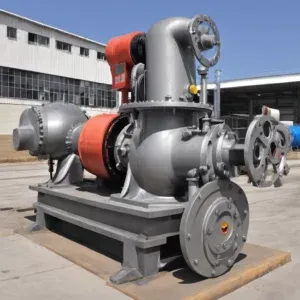 Industrial Pump
Industrial pumps are found in virtually every process plant: water treatment, oil and gas production, chemical manufacturing, food and beverage, pharmaceuticals, mining, and power generation. Applications range from wellhead water injection at 10,000+ psi to low-head cooling water circulation in power plants. In the oil and gas sector alone, a single refinery may have hundreds of pumps in service at any given time, making them one of the most important (and maintenance-intensive) equipment categories.
Key Parts and Components
Every industrial pump, whether centrifugal or positive displacement, shares a common anatomy. The table below covers the main components.
| Component | Function | Notes |
|---|---|---|
| Casing | Contains the fluid, sustains operating pressure, directs flow from suction to discharge | Volute type (most common) or diffuser type |
| Impeller | Rotating vaned element that imparts kinetic energy to the fluid | Material depends on service: cast iron, SS 316, duplex, Hastelloy, etc. |
| Shaft | Transmits torque from the driver to the impeller | Must resist torsional and bending stresses |
| Bearings | Support the shaft, absorb radial and axial loads | Grease- or oil-lubricated; key to long-term reliability |
| Seal | Prevents fluid leakage along the shaft | Packing (traditional) or mechanical seal (modern, better for high pressure and hazardous service) |
| Suction nozzle | Fluid inlet | Smooth approach needed to avoid turbulence |
| Discharge nozzle | Fluid outlet | Directs pumped fluid into the discharge piping |
| Coupling | Connects pump shaft to motor shaft | Compensates for minor misalignment; absorbs shock |
| Baseplate | Stable foundation for pump and driver | Maintains alignment; simplifies installation |
| Motor / Driver | Provides mechanical energy | Electric motor, diesel engine, or steam turbine |
Types of Industrial Pumps
The two fundamental pump categories are centrifugal and positive displacement. Every pump on the market falls into one of these families.
1. Centrifugal Pumps
A centrifugal pump spins an impeller to convert mechanical energy into kinetic energy in the fluid. The casing then converts that velocity into pressure. Simple principle, enormous range of applications, from crude oil transfer to cooling water circulation.
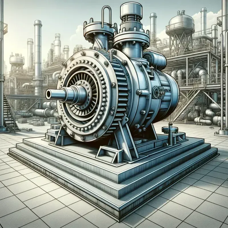 Centrifugal pump for oil and gas
In oil and gas, centrifugal pumps cover upstream water injection and produced water handling, midstream pipeline transfer of crude and condensate, and downstream refinery circulation and cooling duties.
Why centrifugal pumps dominate the industry: they handle high flow rates with fewer moving parts than PD pumps, which means less maintenance and lower energy cost per barrel moved. The tradeoff is that they struggle with high-viscosity fluids and lose efficiency quickly when operated far from the BEP.
When selecting a centrifugal pump, pay attention to fluid properties (viscosity, corrosiveness, solids), operating conditions (flow, head, temperature), available space (horizontal vs. vertical configuration), and the applicable standard (API 610 for O&G, ANSI B73.1 for chemical service).
The two main challenges are cavitation (covered in detail below) and wear/corrosion when handling abrasive or aggressive fluids, both addressed through proper material selection and operating the pump within its design envelope.
2. Positive Displacement Pumps
PD pumps trap a fixed volume of fluid per cycle and push it forward regardless of downstream pressure. This makes them the go-to choice for high-viscosity fluids, precise dosing, or situations where you need a constant flow rate independent of pressure.
Rotary types:
| Type | How It Works | Typical Use | API Standard |
|---|---|---|---|
| Gear pump | Two interlocking gears trap and move fluid | Lube oil, fuel oil, high-viscosity fluids | API 676 |
| Screw pump | One or more helical screws advance fluid axially | Crude oil transfer, multiphase boosting | API 676 |
| Lobe pump | Rotating lobes move fluid gently | Food/beverage, sanitary applications | API 676 |
Reciprocating types:
| Type | How It Works | Typical Use | API Standard |
|---|---|---|---|
| Piston/plunger pump | Piston reciprocates in a cylinder | High-pressure injection, hydraulic systems | API 674 |
| Diaphragm pump | Flexible diaphragm flexes to create suction/discharge | Hazardous chemicals, slurries (fluid never contacts the drive side) | API 675 |
| Metering pump | Precision reciprocating PD pump with adjustable stroke | Chemical injection (corrosion inhibitors, biocides, scale inhibitors) | API 675 |
3. Submersible Pumps
Submersible pumps sit inside the fluid they pump, so there is no suction lift and no cavitation from elevation difference. Common in well water extraction, sewage handling, and drainage. In oil and gas, Electric Submersible Pumps (ESPs) are a key artificial lift method for high-volume wells.
4. AODD (Air-Operated Double Diaphragm) Pumps
These use compressed air to alternately flex two diaphragms. They are self-priming, can run dry without damage, and handle chemicals, viscous liquids, and slurries well. You see them everywhere in chemical plants for utility and transfer duties.
5. Multiphase Pumps
Multiphase pumps transport a mixed stream of gas, oil, water, and sometimes sand as a single fluid, without a separator at the wellhead. This eliminates the need for test separators, individual flowlines, and associated topsides equipment, which is a major cost saving on offshore platforms and remote onshore fields.
The key design parameter is Gas Volume Fraction (GVF), the ratio of gas to total fluid. A good multiphase pump handles anywhere from near-100% liquid to near-100% gas.
| Type | Principle | Best For |
|---|---|---|
| Twin-screw | Two intermeshing screws trap and advance the mixture | Consistent flow rate regardless of pressure; handles high GVF and slugging |
| Helico-axial | Combined axial and centrifugal action via helical rotor | High flow rates, moderate pressure boost |
| Progressive cavity | Single helical rotor in elastomer stator creates advancing cavities | Highly viscous fluids, high GVF, lower flow rates |
Centrifugal vs. Positive Displacement vs. Reciprocating: Comparison
Choosing the right pump family is the first and most consequential decision in the selection process. The table below provides a direct comparison.
| Parameter | Centrifugal | Rotary PD (Gear/Screw) | Reciprocating PD (Piston/Diaphragm) |
|---|---|---|---|
| Flow behavior | Variable (depends on head) | Nearly constant (independent of pressure) | Pulsating (requires dampeners) |
| Typical flow range | 1 to 100,000+ m3/h | 0.1 to 5,000 m3/h | 0.01 to 500 m3/h |
| Pressure range | Low to moderate (up to ~250 bar multistage) | Moderate (up to ~50 bar) | Very high (up to 1,000+ bar) |
| Viscosity handling | Poor above ~200 cP | Excellent (up to 1,000,000 cP) | Good (up to ~10,000 cP) |
| Efficiency at off-design | Drops rapidly away from BEP | Relatively stable | Relatively stable |
| Solids tolerance | Limited (wear issues) | Moderate (twin-screw can handle some solids) | Good (diaphragm type best for slurries) |
| Self-priming | No (needs priming) | Yes | Yes |
| Maintenance complexity | Low (fewer moving parts) | Moderate | Higher (valves, packing, diaphragms) |
| Best for | High flow, low viscosity, continuous duty | Viscous fluids, lube oil, fuel oil | High pressure injection, precise metering |
API 610 Centrifugal Pump Types
API 610 (also published as ISO 13709) is the governing specification for centrifugal pumps in petroleum, petrochemical, and natural gas service. If you are buying a centrifugal pump for an oil refinery, gas plant, or offshore platform, API 610 is the standard you will reference.
The standard classifies centrifugal pumps into three families and 17 specific configurations. Understanding these designations is essential for specifying the correct pump for each service.
Overhung (OH) Types
In overhung pumps, the impeller is mounted on the end of the shaft, cantilevered beyond the bearing housing. These are the most common pump types for general process duty.
| Type | Name | Description | Typical Application |
|---|---|---|---|
| OH1 | Foot-mounted, flexibly coupled | Standard horizontal end-suction pump on a baseplate | General process, cooling water, condensate |
| OH2 | Centerline-mounted, flexibly coupled | Casing supported at the shaft centerline for thermal stability | Hot services (above 175 degC): hot oil, boiler feed water |
| OH3 | Vertical in-line, flexibly coupled | Suction and discharge nozzles in-line; saves floor space | Space-constrained installations, moderate duty |
| OH4 | Rigidly coupled, close-coupled | Impeller mounted directly on the motor shaft; no coupling | Low-cost, compact applications; utility water |
| OH5 | Close-coupled, with integral bearing | Similar to OH4 but with an integrated bearing frame | Moderate-duty chemical process |
Between Bearings (BB) Types
In BB pumps, the impeller(s) sit between two bearing housings. This provides superior rotor stability and allows for multistage designs at higher pressures and speeds.
| Type | Name | Description | Typical Application |
|---|---|---|---|
| BB1 | Axially split, single stage | Horizontally split casing for easy maintenance access | Large-volume crude transfer, pipeline service |
| BB2 | Radially split, single stage | Barrel-type casing for high-pressure containment | High-pressure process, hydrocarbon service |
| BB3 | Axially split, multistage | Horizontally split with multiple impellers in series | Moderate-pressure multistage (boiler feed water) |
| BB4 | Radially split, single-casing multistage | Single barrel casing with multistage rotor | High-pressure injection (water injection, pipeline) |
| BB5 | Radially split, double-casing multistage | Inner cartridge inside an outer barrel | Very high pressure; boiler feed, high-head injection |
Vertically Suspended (VS) Types
VS pumps hang vertically into a pit, sump, tank, or vessel. The motor sits above the mounting plate, and the pump extends downward into the fluid.
| Type | Name | Description | Typical Application |
|---|---|---|---|
| VS1 | Vertical sump, single-casing | Single-casing pump suspended in a wet pit | Cooling water intake, drainage |
| VS2 | Vertical sump, diffuser type | Diffuser-type casing for higher head | Deep-well pumps, large cooling water systems |
| VS3 | Vertical sump, double-casing | Double-casing (barrel) for high-pressure containment | High-pressure well pumps |
| VS4 | Vertical sump, line-shaft driven | Long line shaft connects motor above to pump below | Deep-set pump in wells, dewatering |
| VS5 | Vertical sump, cantilever | No submerged bearings; shaft cantilevers from above | Corrosive or abrasive sumps where submerged bearings would fail |
| VS6 | Vertical sump, submersible motor driven | Motor submerged with the pump | ESP (Electric Submersible Pump), borehole applications |
| VS7 | Vertical sump, axial flow | Axial (propeller) type for very high flow, low head | Large circulating water systems, flood control |
Key Takeaway: API 610 defines 17 pump configurations across three families (OH, BB, VS). Selecting the right configuration depends on the service conditions: OH types for general process duty, BB types for high-pressure or multistage service, and VS types for submerged or vertical installations. Always match the configuration to the temperature, pressure, and installation constraints of your specific application.
Pump Curves and Performance Parameters
Understanding Pump Curves
Every centrifugal pump ships with a set of performance curves. You need to read them; the datasheet alone is not enough.
| Curve | What It Shows | Why It Matters |
|---|---|---|
| Head vs. Flow (H-Q) | Discharge head at each flow rate | Core selection tool; overlay this on your system curve |
| Efficiency | Pump efficiency across the flow range | Peaks at the Best Efficiency Point (BEP); stay close to it |
| Power | Brake horsepower at each flow rate | Determines motor sizing |
| NPSHr | Required NPSH at each flow rate | Must stay below NPSHa to avoid cavitation |
The system curve is a plot of total system resistance (static head plus friction losses) against flow rate. Where the system curve intersects the pump’s H-Q curve is your operating point. That operating point must fall between 80% and 110% of BEP for reliable long-term operation.
The pump affinity laws govern how changes in impeller speed affect performance: flow changes proportionally with speed, head changes with the square of speed, and power changes with the cube of speed. This is why variable frequency drives (VFDs) are so effective at saving energy: a 20% speed reduction cuts power consumption by nearly 50%.
Key Performance Parameters
| Parameter | Symbol | Definition | Unit |
|---|---|---|---|
| Flow rate | Q | Volume of fluid delivered per unit time | m3/h, GPM |
| Total Dynamic Head | TDH | Total energy added to the fluid (suction to discharge) | meters, feet |
| Best Efficiency Point | BEP | Flow rate at which the pump operates at peak efficiency | m3/h, GPM |
| Brake Horsepower | BHP | Power input to the pump shaft from the driver | kW, HP |
| Pump Efficiency | eta | Ratio of hydraulic power output to mechanical power input | % |
| Specific Speed | Ns | Dimensionless number relating speed, flow, and head; indicates impeller geometry | - |
| Minimum Continuous Stable Flow | MCSF | Lowest flow at which the pump can operate without recirculation damage | m3/h, GPM |
NPSH: Net Positive Suction Head
NPSH is one of the most important, and most commonly misunderstood, parameters in pump engineering. Getting it wrong causes cavitation, which destroys impellers and costs far more than the engineering time to calculate it properly.
NPSHa (Available)
NPSHa is the energy available in the fluid at the pump suction flange, above the vapor pressure. It is a property of the system, not the pump, and is calculated as:
NPSHa = (P_surface - P_vapor) / (rho x g) + H_static - H_friction
Where:
- P_surface = absolute pressure at the liquid surface (atmospheric for open tanks, vessel pressure for closed systems)
- P_vapor = vapor pressure of the liquid at pumping temperature
- rho = fluid density
- g = gravitational acceleration
- H_static = elevation of the liquid surface above (+) or below (-) the pump suction centerline
- H_friction = friction losses in the suction piping (including strainers, valves, bends)
NPSHr (Required)
NPSHr is the minimum suction head the pump needs to avoid cavitation. It is a property of the pump, determined by the manufacturer through testing (per HI 1.6 or API 610 test protocol). NPSHr increases with flow rate: it is lowest near shutoff and highest at maximum flow.
NPSH Margin
The fundamental rule: NPSHa must always exceed NPSHr at the operating point, with a safety margin. API 610 specifies a minimum margin, but experienced engineers add more to account for:
- Strainer fouling (increases suction friction losses over time)
- Process upsets (temperature excursions raise vapor pressure, lowering NPSHa)
- Pump degradation (NPSHr increases as impeller wear rings open up)
- Measurement uncertainty (suction piping pressure losses are estimates)
Cavitation
Cavitation occurs when local pressure inside the pump drops below the liquid’s vapor pressure. Vapor bubbles form, travel to higher-pressure zones, and collapse violently, pitting the impeller and eroding the casing.
Common causes: excessive suction lift, high fluid temperature, partially blocked suction strainers, or sharp bends in the suction piping.
Symptoms: crackling noise (sounds like gravel in the pump), fluctuating discharge pressure, vibration spikes, and visible pitting on the impeller eye.
Prevention: maintain adequate NPSHa (with margin), minimize suction piping losses, keep fluid temperature stable, and use a VFD to avoid running the pump far off its BEP. If the layout cannot provide enough NPSHa, consider using an inducer (a small axial impeller installed ahead of the main impeller) or switching to a pump with a lower NPSHr.
Pump Sealing Systems
The shaft seal is the most maintenance-intensive component on a centrifugal pump. In oil and gas service, the seal must contain hazardous fluids at elevated temperatures and pressures while allowing the shaft to rotate at thousands of RPM. API 682 defines mechanical seal requirements for API 610 pumps.
Mechanical Seals (API 682)
| Arrangement | Description | Application |
|---|---|---|
| Arrangement 1 | Single mechanical seal | Non-hazardous services; water, cooling fluids |
| Arrangement 2 | Dual unpressurized (tandem) seals with buffer fluid | Moderate-risk services; the buffer fluid absorbs minor leakage and enables leak detection |
| Arrangement 3 | Dual pressurized seals with barrier fluid | Hazardous, toxic, or flammable fluids; barrier fluid at higher pressure than process prevents any process leakage |
API 682 also defines seal piping plans (Plan 11, 13, 21, 23, 32, 52, 53A/B/C, 54, etc.) that specify the auxiliary systems for cooling, flushing, quenching, and pressurizing the seal chamber.
Traditional Packing
Braided packing rings compressed by a gland into a stuffing box. Still used on some water and utility services where minor controlled leakage is acceptable. Not suitable for hazardous or high-temperature service. Requires regular adjustment and is being phased out in favor of mechanical seals on most new installations.
Sealless Pumps (API 685)
For the most hazardous services, sealless pumps eliminate the shaft seal entirely:
- Magnetic-drive (mag-drive): An outer magnet set on the motor side drives an inner magnet set on the impeller side through a containment shell. No dynamic seal. Limited by temperature (containment shell material) and power (eddy current losses in the shell).
- Canned-motor: The motor rotor is enclosed in a sealed can, directly coupled to the impeller. The process fluid lubricates the bearings. Higher efficiency than mag-drive but more complex to maintain.
Materials of Construction
Material selection drives pump life and maintenance cost more than almost any other factor. Get it wrong and you are replacing impellers every turnaround; get it right and the pump runs for a decade between overhauls.
API 610 Material Classes
API 610 defines standard material classes (previously called “material class” and now aligned with ISO 13709 designations) for wetted pump components. The table below summarizes the most commonly specified classes.
| Material Class | Casing | Impeller | Shaft | Typical Service |
|---|---|---|---|---|
| S-1 (C-6) | Carbon steel | Carbon steel | Carbon steel or 4140 | Non-corrosive hydrocarbons at moderate temperature |
| S-3 (C-6) | Carbon steel | 12% Cr steel | 4140 or 410 SS | Mildly corrosive hydrocarbons, produced water |
| S-4 (C-6) | Carbon steel | CF8M (316 SS cast) | 316 SS | Moderately corrosive services |
| S-6 (A-8) | 316 SS | 316 SS | 316 SS | Corrosive chemicals, acids, seawater |
| S-8 (D-1) | Duplex SS | Duplex SS | Duplex SS | Severe chloride corrosion, offshore seawater |
| A-7 | Alloy 20 (CN7M) | Alloy 20 | Alloy 20 | Sulfuric acid service |
| C-6 | Ni-Al Bronze | Ni-Al Bronze | Monel | Seawater fire-fighting pumps |
General Materials Guide
| Material | Key Properties | Typical Applications |
|---|---|---|
| Cast Iron | Good mechanical strength, cost-effective, limited corrosion resistance | Water, sewage, non-corrosive fluids; general service centrifugal pumps |
| Carbon Steel | Higher strength and thermal stability than cast iron; requires corrosion protection | High temperature/pressure applications; pipeline and boiler feed water pumps |
| Stainless Steel (304/316) | Excellent corrosion resistance; Type 316 adds molybdenum for chloride environments | Corrosive liquids, sanitary applications; chemical/food processing, pharmaceuticals |
| Duplex Stainless Steel | High strength, superior chloride-induced corrosion resistance | Severe corrosive environments; offshore and subsea applications |
| Nickel Alloys (Hastelloy, Inconel, Monel) | Exceptional corrosion resistance in acidic/alkaline environments; high temperature resistance | Chemical processing, nuclear power, aerospace |
| Titanium | Exceptional corrosion resistance, lightweight, high strength-to-weight ratio; expensive | Desalination plants, offshore platforms, chemical processing |
| Plastics/Composites (PP, PVDF, FRP) | Excellent corrosion resistance, lightweight; lower temperature/pressure limits | Highly corrosive fluids; chemical processing, wastewater treatment |
| Ceramics/Tungsten Carbide | Extreme hardness and wear resistance; brittle, can be costly | Abrasive fluids, slurry applications; seals, bearings, impeller trim |
When choosing materials, check the fluid’s chemical compatibility first (use NACE MR0175/ISO 15156 for sour service with H2S), then consider operating temperature and pressure, abrasive content, and any regulatory requirements (e.g., FDA compliance for food-grade pumps). Always balance upfront cost against expected service life; a duplex impeller costs more than carbon steel but may last three times as long in seawater service.
Pump Selection Guide
Step-by-Step Selection Process
Pump selection boils down to five questions:
- What are the fluid properties? Viscosity, temperature, corrosiveness, and solids content narrow the pump type immediately. High viscosity or solids? Think positive displacement. Clean, low-viscosity liquid at high flow? Centrifugal.
- What flow rate and head do you need? Plot your system curve (static head + friction losses at various flows) and overlay candidate pump curves.
- What is the available NPSH? Calculate NPSHa from your piping layout and verify the pump’s NPSHr sits well below it, with margin.
- What is the operating environment? Ambient temperature, hazardous area classification, and space constraints all affect pump configuration and material choices.
- What does the total cost of ownership look like? A cheaper pump that eats seals every six months is not cheaper. Factor in energy, spare parts, and downtime.
Which Pump for Which Service
| Service | Recommended Pump Type | Why |
|---|---|---|
| Crude oil transfer (pipeline) | Centrifugal (BB1 or BB3) | High flow, moderate head, continuous duty |
| Water injection (high pressure) | Centrifugal multistage (BB4 or BB5) | Very high head, continuous duty, seawater compatible |
| Lube oil circulation | Gear pump (PD) or screw pump | Viscous fluid, constant flow needed |
| Chemical injection (corrosion inhibitor) | Metering/diaphragm pump | Precise dosing, low flow, hazardous fluid |
| Cooling water | Centrifugal (VS1 or OH1) | High flow, low head, low cost |
| Condensate return | Centrifugal (OH2) | Moderate flow, high temperature |
| Slurry/produced sand | Centrifugal with hard trim or diaphragm PD | Abrasion resistance is the priority |
| Wellhead multiphase | Twin-screw or helico-axial | Handles gas/oil/water mixture, variable GVF |
| Boiler feed water | Centrifugal multistage (BB3 or BB5) | High pressure, high temperature, critical service |
| Sour hydrocarbon (H2S) | Centrifugal with NACE materials + Arr. 3 seal | Hazardous fluid, zero-leak requirement |
Key Takeaway: Pump selection for oil and gas service must balance hydraulic requirements (flow rate, head, NPSH), fluid properties (viscosity, corrosiveness, solids content), and compliance with industry standards like API 610 for centrifugal pumps. Always target operation near the Best Efficiency Point (BEP) for reliability and longevity, and select materials per NACE MR0175 for sour service.
Industry Standards Reference
Pump Standards
| Standard | Title | Scope |
|---|---|---|
| API 610 (ISO 13709) | Centrifugal Pumps for Petroleum, Petrochemical, and Natural Gas Industries | Design, materials, manufacturing, testing for centrifugal pumps in high-temperature/high-pressure O&G service |
| API 674 | Positive Displacement Pumps - Reciprocating | Reciprocating PD pumps (plunger, piston) for petroleum and petrochemical service |
| API 675 | Positive Displacement Pumps - Controlled Volume (Metering) | Metering/dosing pumps for precise chemical injection |
| API 676 | Positive Displacement Pumps - Rotary | Rotary PD pumps (gear, screw, lobe) for petroleum and petrochemical service |
| API 682 | Pumps - Shaft Sealing Systems | Mechanical seal requirements for API 610 pumps; defines arrangements, materials, and piping plans |
| API 685 | Sealless Centrifugal Pumps | Sealless (mag-drive / canned motor) centrifugal pumps for hazardous process service |
| ANSI/ASME B73.1 | Horizontal End Suction Centrifugal Pumps for Chemical Process | Single-stage, end-suction horizontal pumps, the workhorse of chemical plants |
| ANSI/ASME B73.2 | Vertical In-line Centrifugal Pumps for Chemical Process | Same scope as B73.1 but vertical in-line configuration |
| ANSI/HI | Hydraulic Institute Standards | Broad guidelines covering design, installation, operation, and maintenance for all pump types |
| ISO 5199 | Centrifugal Pumps - Class II | Intermediate-duty centrifugal pumps for general industrial service |
| ISO 2858 | End-suction Centrifugal Pumps (16 bar) | Dimensional interchangeability standard for end-suction pumps |
| ISO 9905 | Centrifugal Pumps - Class I | Stringent requirements for heavy-duty industrial centrifugal pumps |
In practice, if you work in oil and gas, API 610 is the default centrifugal pump spec and API 674/675/676 cover PD pumps. For chemical plants, you will more often see ANSI/ASME B73.1. ISO standards appear on projects outside North America or when the client specifies them.
Installation and Commissioning Guidelines
Proper installation is as important as proper selection. A well-chosen pump installed poorly will fail just as fast as a poorly chosen pump.
Installation Checklist
- Foundation and baseplate: Grout the baseplate on a level foundation. The foundation mass should be at least 3 times the combined weight of pump, driver, and baseplate to dampen vibration.
- Alignment: Perform both angular and parallel alignment using dial indicators or laser alignment tools. Record readings. API 610 specifies maximum allowable misalignment values.
- Piping connections: The piping must not impose strain on the pump nozzles. Support the piping independently. Use expansion joints or loops where thermal growth is expected. Eccentric reducers (flat side up) on horizontal suction lines prevent air pockets.
- Suction piping: Keep suction piping as short and straight as possible. Provide at least 5 pipe diameters of straight run before the pump suction nozzle. Avoid high points that trap gas.
- Baseplate leveling: Level the baseplate to within 0.05 mm/m (0.001 in/ft) before grouting.
- Coupling installation: Follow the coupling manufacturer’s instructions for gap and alignment tolerances. Install the coupling guard before starting the pump.
Commissioning Steps
- Pre-commissioning checks: Verify rotation direction (bump the motor briefly), check bearing lubrication levels, confirm all temporary strainer/startup strainers are installed, and verify all instrumentation is functional.
- Initial startup: Fill the pump casing and suction line completely (vent all air). Open the suction valve fully. Open the discharge valve slightly (about 20-30% for centrifugal pumps, or per manufacturer recommendation). Start the motor.
- Post-start monitoring: Check for vibration, bearing temperature, seal leakage, suction and discharge pressures, and motor current. All parameters should stabilize within the first few minutes.
- Hot alignment check: After the pump reaches normal operating temperature (typically 2-4 hours of running), shut down briefly and re-check alignment. Adjust if needed. This is the final alignment.
- Performance verification: Compare actual operating parameters (flow, head, power, vibration) against the datasheet. Document all readings for future reference.
How to Order a Pump
When you send an RFQ to a pump vendor, the more complete your data, the faster and more accurate the proposal. Incomplete data sheets are the number-one cause of wrong pump selections. At minimum, provide the following:
| Parameter | Details to Provide |
|---|---|
| 1. Type of Pump | Centrifugal, positive displacement, submersible, etc. |
| 2. Fluid Characteristics | Type (water, oil, chemical, slurry); temperature (min/max/operating); viscosity; corrosiveness (pH, chemical composition); solids content (size, concentration); specific gravity |
| 3. Flow Rate | Required flow rate in GPM or m3/h (rated, normal, minimum, maximum) |
| 4. Total Dynamic Head (TDH) | Total lift height including static lift and friction losses (feet or meters) |
| 5. Pressure Requirements | Suction pressure (at pump inlet); discharge pressure (at pump outlet plus system requirements) |
| 6. Power Supply | Voltage, phase, frequency to verify motor compatibility |
| 7. Operating Environment | Ambient temperature; hazardous area classification (explosion-proof ratings); outdoor/indoor location |
| 8. Connection Type | Flanged, threaded, etc.; size for suction and discharge ports |
| 9. Material of Construction | Preferred materials for pump casing, impeller, shaft, and seals |
| 10. Sealing Requirements | Mechanical seals or packing; specific seal arrangement (API 682 Arr. 1/2/3); seal piping plan |
| 11. Regulatory/Certification | Industry or governmental standards (API 610, API 674/675/676, ANSI, ISO, NACE MR0175) |
| 12. Additional Features | Control/monitoring (sensors, controllers, remote monitoring); special coatings/treatments; accessories (baseplates, coupling guards, vibration monitors) |
| 13. Documentation/Support | Required documentation (manuals, performance curves, CAD drawings); after-sales support services |
Missing even one of these parameters (especially fluid temperature or viscosity) can result in a pump that looks right on paper but fails in the field.
Frequently Asked Questions
What is the difference between centrifugal and positive displacement pumps?
Centrifugal pumps use a rotating impeller to convert mechanical energy into kinetic energy and then pressure, delivering high flow rates at moderate pressures. Positive displacement (PD) pumps trap a fixed volume of fluid per cycle and push it forward, delivering constant flow regardless of discharge pressure. Centrifugal pumps are best for clean, low-viscosity fluids at high flow rates; PD pumps excel with viscous fluids, precise metering, and high-pressure applications.
What is NPSH and why does it matter for pump selection?
NPSH stands for Net Positive Suction Head. NPSHa (available) is the absolute pressure at the pump suction minus the fluid vapor pressure, determined by your system layout. NPSHr (required) is the minimum suction head the pump needs to avoid cavitation, determined by pump design. NPSHa must always exceed NPSHr with a safety margin (typically 1-2 meters or per API 610 requirements). Insufficient NPSH causes cavitation, which damages the impeller and reduces pump life dramatically.
What are the API 610 pump type designations (OH, BB, VS)?
API 610 classifies centrifugal pumps into three families: OH (Overhung) types OH1-OH5 where the impeller is cantilevered beyond the bearings; BB (Between Bearings) types BB1-BB5 where the impeller sits between two bearing housings for better stability; and VS (Vertically Suspended) types VS1-VS7 for submerged or vertical applications. Each designation defines a specific configuration suited to particular services, pressures, and installation requirements.
What seal types are used in API 610 pumps?
API 610 pumps primarily use mechanical seals per API 682. The main arrangements are: Arrangement 1 (single seal) for non-hazardous services, Arrangement 2 (dual unpressurized/tandem seal) for moderate-risk services where leakage monitoring is needed, and Arrangement 3 (dual pressurized seal) for hazardous and toxic services where zero leakage is required. Sealless alternatives (magnetic-drive and canned-motor pumps per API 685) are available for highly toxic or dangerous fluids.
How do I select the right pump for an oil and gas application?
Start with fluid properties (viscosity, temperature, corrosiveness, solids content) to narrow the pump type. Plot your system curve (static head plus friction losses) to determine required flow and head. Calculate NPSHa to verify the pump will not cavitate. Check API 610 material classes for compatibility with the process fluid. Select a pump that operates between 80-110% of its Best Efficiency Point (BEP) at normal conditions, and size the motor with adequate margin. Always consider total cost of ownership (energy, spare parts, and downtime), not just purchase price.
Leave a Comment
Have a question or feedback? Send us a message.