API Choke Valves
Choke Valve
What Is a Choke Valve?
Definition: A choke valve is a flow-control device that regulates fluid flow and reduces pressure by restricting the flow path through a variable or fixed orifice. Choke valves are critical in upstream oil and gas operations for controlling well flow rates, managing pressure differentials, and protecting downstream equipment.
API choke valves control pressure and flow in upstream oil and gas operations, from wellheads and Christmas trees to test separators and production manifolds. Built to API 6A, they handle high pressures, corrosive well fluids, and multi-phase flow (oil, gas, water, and sand all at once).
 Choke Valve
The two broad categories are positive chokes (fixed orifice, no moving parts in the flow path) and adjustable chokes (variable orifice controlled by needle, plug, or external sleeve). This article focuses on oil and gas choke valves, though you will find them in chemical plants, power generation, and water treatment as well.

Function of Choke Valves
In practical terms, a choke valve does three things on a wellsite: it sets the production flow rate, it drops pressure from reservoir levels down to what your surface equipment can handle, and it gives you a way to shut things down fast when something goes wrong.
Beyond that, choke valves help manage multi-phase flow (oil, gas, water, and sometimes sand), reduce cavitation risk by controlling velocity, and maintain the backpressure needed for proper separator performance. In gas-lift systems, they meter the injection gas; during production testing, they hold a steady flow rate so the test separator can give you accurate water cut and GOR readings.
 API choke valves
Applications
The table below lists typical choke valve applications by industry:
| Industry | Typical Applications |
|---|---|
| Oil & Gas | Wellhead flow/pressure control, flowback after frac, underbalanced drilling, production testing, gas lift, manifold systems |
| Chemical / Petrochemical | Reactor feed control, corrosive fluid handling |
| Water Treatment | Pipeline pressure management, treatment plant flow control |
| Power Generation | Steam flow to turbines, cooling water regulation |
| Mining | Slurry flow regulation, dust suppression water systems |
| Maritime / Offshore | Ballast water management, fire protection systems |
Components of Choke Valves
The internals vary by mechanism type (orifice, piston, plug, cage, sleeve, rotary), but the general component breakdown for an API 6A choke valve is:
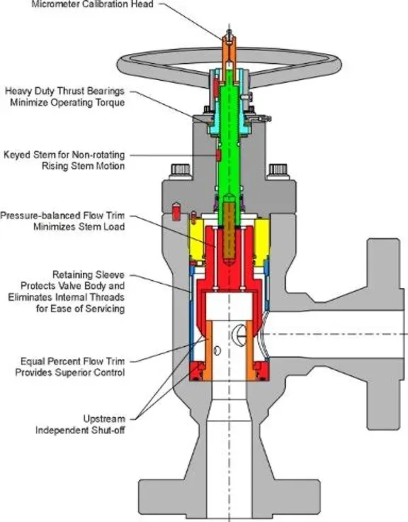 Choke valve parts (Source: Cesare Bonetti)
| Component | Function |
|---|---|
| Body | Main pressure-containing structure; connects to pipeline or wellhead. |
| Bonnet | Removable closure that gives access to internals for maintenance. |
| Stem (or Shaft) | Moves the disc or plug to change the flow area. |
| Seat | Mates with the disc/plug to form the sealing surface. |
| Disc or Plug | The throttling element; its position sets the flow rate. |
| Actuator | Drives the stem. Can be manual (handwheel), pneumatic, hydraulic, or electric. |
| Seals and Gaskets | Prevent external leaks; material selected for the service fluid. |
| Trim | All wetted parts (seat, disc, stem), material chosen for erosion and corrosion resistance. |
| Flow Bean / Choke Bean | Fixed-orifice insert used in positive choke valves; swapped out for a different size to change flow rate. |
| Position Indicator | On adjustable chokes, shows the current opening percentage. |
Learn more about the typical components of valves.
Opening/Closing Mechanisms
Orifice (Needle)
A fixed or changeable orifice plate sets the flow rate: smaller hole, less flow. Simple, reliable, and the go-to choice when flow conditions are stable and you just need a predictable restriction.
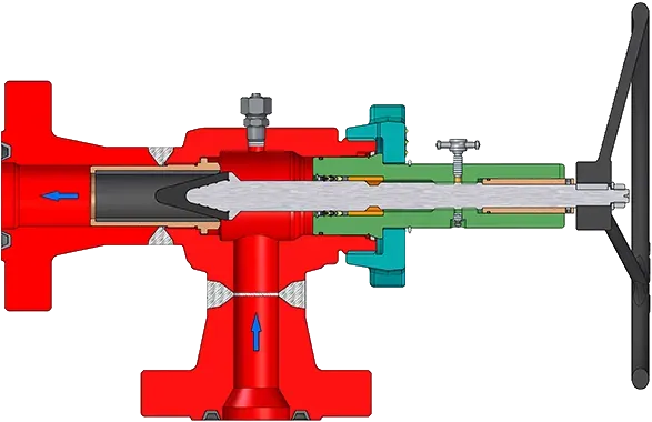 Orifice Choke Valve (Source: JVS Engineers)
Plug & Cage
A conical or cylindrical plug moves within the valve body to vary the flow area. The tapered profile gives fine control, which makes it the standard choice where operators need to adjust flow rates frequently.
 Plug Choke Valve (Source: Quam Valvole)
Piston
A piston slides within a cylindrical chamber to alter the flow path. Durable in high-pressure service and handles slurries and high-viscosity fluids well because the sealing surfaces stay out of the direct flow stream.
Cage
A cage surrounds the plug or piston, stabilizing it and reducing vibration. The cage has multiple ports that align with the plug position. This is the mechanism of choice when you have turbulent flow or need consistent control across a wide range of flow rates. The cage also extends trim life by supporting the moving parts.
Sleeve
A movable sleeve covers or uncovers ports in the valve body. The streamlined flow path minimizes turbulence and erosion, so sleeve chokes tend to last longer in sandy or erosive service.
Rotary Disc
A disc rotates inside the body to open or close the flow path. Fast-acting, and less prone to clogging when the fluid carries solids.
 Rotary Disc Choke Valve (Source: Quam Valvole)
Ball
A rotating ball with a bore through it aligns with the flow path to throttle or shut off flow. Tight-sealing and quick to operate, it works for both clean and dirty service.
Applicable Standards
The primary standard is API Spec 6A (ISO 10423), which covers wellhead and Christmas tree equipment, including choke valves for drilling and production. For choke and kill systems specifically, refer to API Spec 16C.
| Standard | Scope |
|---|---|
| API 6A / ISO 10423 | Wellhead and Christmas tree equipment (primary choke valve standard) |
| API 16C | Choke and kill systems for drilling |
| ASME B16.34 | Pressure-temperature ratings, materials, and testing for flanged/threaded/welded valves |
| ASME B16.5 | Flanged fittings dimensions and ratings |
| ASME B31.3 | Process piping design, installation, inspection |
| ASME B31.4 | Pipeline systems for liquids and slurries |
| ASME B31.8 | Gas transmission and distribution piping |
| ISO 5208 | Pressure testing of industrial valves |
| EN ISO 10423 | European adoption of ISO 10423 (equivalent to API 6A) |
| ISO 17078-2 | Flow-control devices for side-pocket mandrels |
| ISO 14313 | Pipeline valve design, manufacturing, and testing |
ASME does not have a choke-valve-specific standard, but choke valves with flanged connections or installed in process/pipeline systems must comply with the relevant ASME B16 and B31 codes listed above.
Types of Choke Valves
API 6A choke valves range from simple manual units for low-medium pressure wells to fully automated or hydraulic types for continuous process control and unmanned locations.
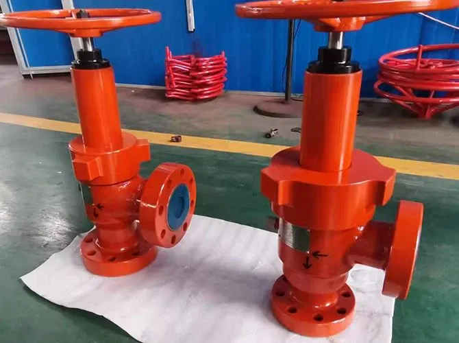
Standard Choke Valves
The workhorse of the oil patch. Manual operation, orifice-type mechanism, handles crude, gas, and water across low-to-medium pressures. You will find these on virtually every conventional onshore wellhead.
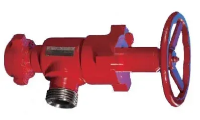 API choke valve
Positive Choke Valves
A positive choke (also called a fixed choke) uses a replaceable bean or orifice insert with no moving parts in the flow path. You pick a bean size, bolt it in, and get a set flow rate. Because nothing moves, positive chokes resist erosion far better than adjustable types, a real advantage on sandy wells. The trade-off: any flow rate change means shutting down and swapping the bean.
Multi-Stage Choke Valves
When you need to drop 10,000+ psi across a single valve, a single-stage choke will cavitate and erode in short order. Multi-stage chokes distribute the pressure reduction across a series of orifices, so no single point sees the full differential. The result: lower velocities at each stage, less noise, less cavitation, and much longer trim life.
 Multistage Choke Valve Detail
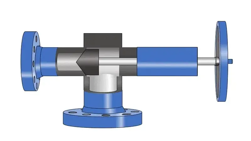
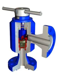
Adjustable Choke Valves
An adjustable choke lets operators change the orifice size on the fly (by handwheel or actuator) without shutting down. This is the standard choice for production testing, wells with changing reservoir pressure, or any situation where you need real-time flow management.
 Adjustable Choke Valve
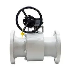
Hydraulic Choke Valves
Hydraulic actuators give you remote operation, which is what you need subsea, on unmanned platforms, or anywhere you cannot (or should not) put an operator next to the valve. Response is fast, and the hydraulic drive handles the high stem forces needed at 10,000-15,000 psi working pressures.
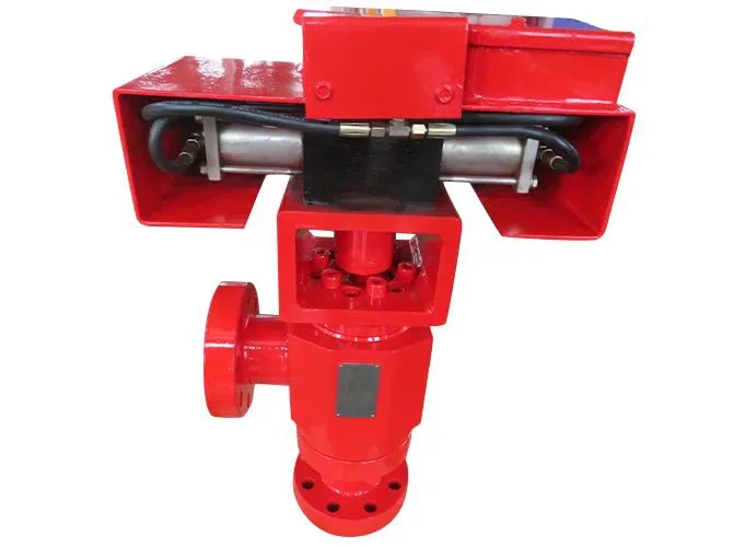 Hydraulic Choke Valve
Automated Choke Valves
Automated chokes incorporate sensors and a control unit that adjusts the orifice based on real-time process data, typically downstream pressure or flow rate. They are standard on modern facilities with DCS/SCADA integration and are required in ESD (emergency shutdown) systems where reaction time matters more than an operator running to a handwheel.
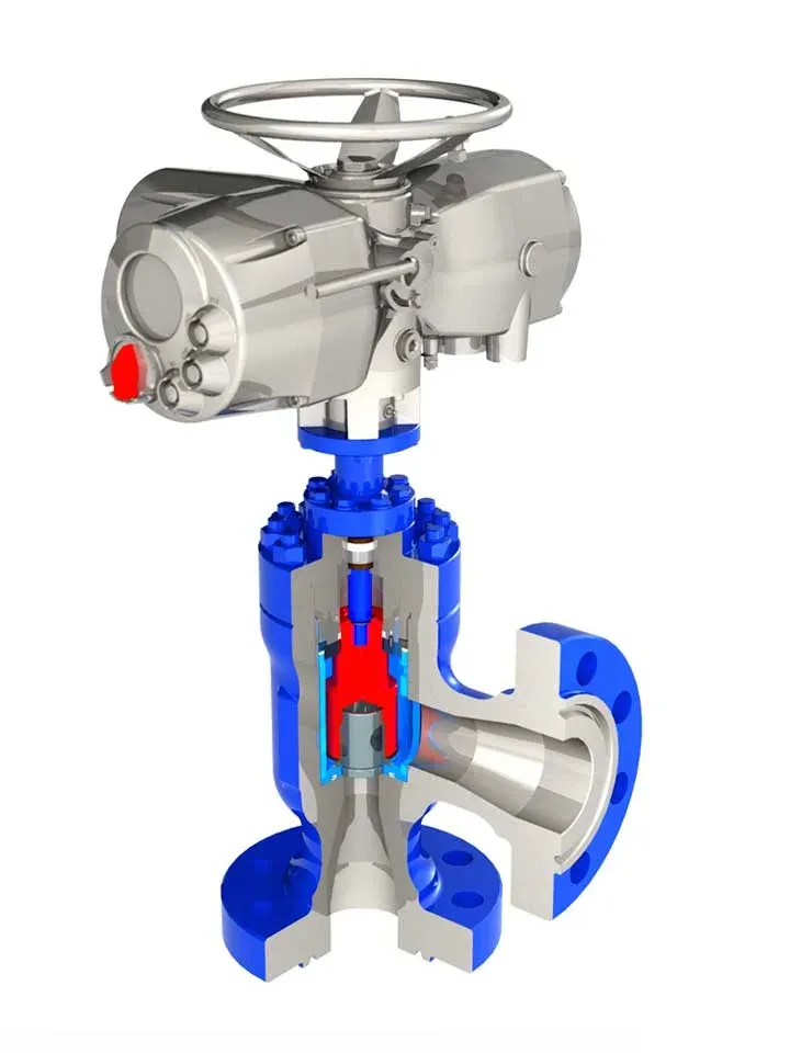 Automated Choke Valve (Source: Quam Valvole)
Cage-Guided Choke Valves
The cage surrounds and guides the plug, damping vibration and providing stable control even in turbulent, fluctuating flow. Cage-guided designs hold up well in harsh environments and are a common choice for high-turndown applications on production platforms.
Sleeve Choke Valves
A cylindrical sleeve slides over a stationary core to modulate the flow area. The streamlined internal geometry limits turbulence, which means less erosion, a significant advantage when handling sand-laden production fluids. Sleeve chokes are popular in the Middle East and other regions with high-sand-cut wells.
Drill Choke Valves
Drill chokes sit on the choke manifold and control drilling mud pressure during kick situations. They see abrasive particles, rapid pressure swings, and the general abuse of a rig floor environment. Heavy-duty construction and easy trim replacement are the priorities here; anything that slows a well-control operation is unacceptable.
Kill Choke Valves
Kill chokes regulate the circulation of kill-weight mud into the wellbore to bring an uncontrolled well back under control. They must handle extreme pressure differentials reliably; there is no second chance during a blowout. Kill chokes are part of every rig’s BOP choke-and-kill manifold and are tested regularly per API 53.
How Choke Valves Work
Flow/Pressure Regulation
Every choke valve works on the same basic principle: force the fluid through a restricted opening, and the velocity goes up while the pressure goes down. That is Bernoulli at work.
With a fixed choke, the restriction is a set orifice size, so you get one flow rate for a given upstream pressure. With an adjustable choke, the operator (or an actuator) varies the opening in real time. Fully open gives maximum flow; fully closed stops it. The useful range is somewhere in between, where the partial restriction creates a controlled pressure drop.
Flow regulation is mechanical: change the opening size (sleeve position, needle travel, disc angle), and you change how many barrels per hour pass through. A positive choke does the same thing passively: the bean size determines the rate.
Pressure regulation happens because the restriction converts pressure energy into velocity. The faster the fluid moves through the throat, the more pressure it gives up. Upstream of the choke, pressure builds (backpressure); downstream, it drops. On a wellhead, this backpressure is what keeps the reservoir from flowing uncontrolled, and the downstream pressure is what your separator and flowline are rated for.
Pressure Drop and Cavitation
Pressure drop across the choke is the whole point: it is how you control flow and protect downstream equipment. But too much drop in a single stage accelerates the fluid to the point where local pressure falls below vapor pressure, and that is when you get cavitation: vapor bubbles form in the throat, travel downstream, and collapse violently. The shockwaves pit and erode valve internals in a matter of weeks on a bad day.
Cavitation is most common when handling liquids near their boiling point or when the pressure differential across the choke is extreme. You will hear it before you see the damage: a distinct crackling or rumbling noise, often with vibration you can feel on the valve body.
Mitigation strategies:
- Multi-stage trim: split the pressure drop across several stages so no single point sees a severe reduction
- Anti-cavitation trim: specially profiled flow paths that keep local velocities below the cavitation threshold
- Correct sizing: an undersized choke forces higher velocity and guarantees cavitation problems
- Hard materials and coatings: tungsten carbide or ceramic trim surfaces tolerate the damage better when some cavitation is unavoidable
Materials for Choke Valves
Material selection drives both the service life and the cost of a choke valve. The body has to contain pressure; the trim has to survive direct contact with the production fluid (sand, CO2, H2S, and all); the seals have to hold up at temperature. Below is a breakdown of common choices.
Body/Bonnet
| Material | Properties |
|---|---|
| Carbon Steel | Good strength at low cost. Fine for standard service, but needs coatings or overlays in corrosive wells. |
| Stainless Steel | Better corrosion resistance; the default upgrade when CO2 or mild sour service is expected. |
| Alloy Steel (Inconel, Monel) | High strength and corrosion resistance for extreme pressures and temperatures (HPHT wells). |
| Duplex / Super Duplex SS | High strength plus outstanding chloride resistance; the standard choice for offshore and subsea chokes. |
| Titanium | Maximum corrosion resistance; used in aggressive environments where the cost is justified. |
Trim
| Material | Properties |
|---|---|
| Hardened Steel | Entry-level trim for moderate sand content and standard pressures. |
| Tungsten Carbide | The go-to for severe erosion/abrasion service; dramatically extends trim life on sandy wells. |
| Ceramics | Extremely hard; used on the most abrasive or corrosive production streams. |
| Alloy 20 (Carpenter 20) | Resists sulfuric acid and aggressive chemicals; common in chemical processing chokes. |
| Hastelloy | Excellent acid resistance; used where strong mineral acids or sour gas are present. |
Sealing
| Material | Properties |
|---|---|
| PTFE (Polytetrafluoroethylene) | Broad chemical resistance, low friction. The default seal material for most services. |
| Nitrile Rubber | Good hydrocarbon resistance at moderate temperatures; common in standard oil and gas service. |
| Viton (Fluoroelastomer) | Handles higher temperatures and more aggressive chemicals than nitrile; used in HPHT and sour service. |
Corrosion and Erosion
Corrosion and erosion are the two failure modes that kill choke valves in the field. They often act together: erosion strips the protective oxide layer, and corrosion attacks the bare metal underneath.
Corrosion comes from the well fluid itself: H2S (sour gas), CO2, chlorides in produced water, and acid treatments. Higher temperatures accelerate every corrosion mechanism. If you spec carbon steel trim on a sour well, expect to replace it in weeks, not months.
Erosion comes from velocity and solids. The choke throat is where fluid velocity is highest, so that is where sand does the most damage. Turbulent flow zones (anywhere the flow path changes direction sharply) are also erosion hot spots.
Mitigation in practice:
- Right material for the service: tungsten carbide or ceramic trim on sandy wells, corrosion-resistant alloys (CRA) on sour or high-CO2 wells
- Protective coatings: nickel-based overlays or ceramic linings on body internals
- Multi-stage trim: spreads the pressure drop and reduces peak velocity at any single point
- Regular inspection: measure orifice diameter at every turnaround; a worn-out bean gives you less pressure drop than you think
- Upstream desanding: a desander or sand screen upstream of the choke can extend trim life dramatically on high-sand-cut wells
API 6A Choke Valve Sizes and Connections
NPS and pressure rating give you the starting point for choke valve selection under API 6A, but the final choice always depends on fluid type, flow rate, temperature, and whether you are dealing with abrasives or corrosives. HPHT developments have pushed available ratings well beyond traditional API 6A classifications.
Sizes
API 6A choke valves typically range from 1-13/16” to 7-1/16” nominal bore. The bore size directly determines flow capacity. Most manufacturers also offer custom sizes within this range for specific well conditions.
Pressure Rating
API 6A pressure rating classes define the maximum non-shock cold working pressure (CWP) in psi:
| Pressure Class | Rating Group |
|---|---|
| 2,000 psi | PR1 |
| 3,000 psi | PR1 |
| 5,000 psi | PR1 |
| 10,000 psi | PR2 |
| 15,000 psi | PR2 |
| 20,000 psi | Recently added for extreme high-pressure environments |
Always select based on the maximum anticipated shut-in pressure, not the average flowing pressure, with an appropriate safety margin.
Factors Influencing Size Selection
Size selection comes down to five things: required flow rate (bigger bore = more capacity), allowable pressure drop (oversizing reduces velocity and erosion), fluid properties (viscosity, solids content, gas fraction), operating pressure and temperature, and physical constraints (weight and space, especially offshore and subsea).
End Connections
| Connection Type | Description | Typical Use |
|---|---|---|
| Flanged | Bolted flange-to-flange with gasket seal. Easy to assemble/disassemble for maintenance. | General onshore and offshore service; most common connection type. |
| Studded | Studs permanently attached to one flange; nuts secure the joint. Less risk of bolt loosening under vibration. | High-pressure and high-vibration installations. |
| Hub (Clamp) | Machined hubs joined by a clamp ring compressing a metal seal ring. Compact, lightweight, metal-to-metal seal. | Subsea, offshore, and HPHT applications where space and weight matter. |
| Hammer Union | Threaded nut tightened by hammer for fast make-up and break-out. | Temporary installations: well testing, flowback, temporary flowlines. Low-to-medium pressure. |
Leave a Comment
Have a question or feedback? Send us a message.
Previous Comments
Thank you, John. I'm glad you found the information provided in the post to be detailed. It's always beneficial to have a comprehensive understanding of API choke valves and their role in controlling flow in upstream oil and gas operations. If you have any specific questions or if there's anything else you would like to discuss regarding this topic, please feel free to let me know.
Team, We have one tender for the choke valve and PSV of the well head, do you have this product?