Flange Isolation Kit Types & Materials
What Is a Flange Isolation Kit?
A flange isolation kit is a set of dielectric components installed between two bolted flanges to break the electrical continuity across the joint. Without isolation, electric current flows freely through the metal-to-metal contact at the flange faces, bolt holes, and bolt/nut bearing surfaces. This current flow enables two destructive mechanisms: galvanic corrosion at dissimilar metal junctions and cathodic protection current drain where protected pipeline sections connect to unprotected structures.
Every flanged connection in a piping system is a potential path for stray currents. When a buried pipeline protected by cathodic protection (CP) connects to above-ground equipment, the protective current intended for the pipeline can drain through the plant, rendering the CP system ineffective. Isolation kits solve this by inserting non-conductive barriers at every point where metal touches metal in the joint.
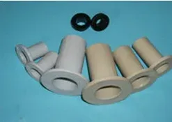
Flange isolation kits interrupt electrical continuity between flanges, preventing electrochemical reactions that cause corrosion. Each kit contains four component types working together to achieve a complete electrical barrier.
Why Electrical Isolation Matters: Cathodic Protection Basics
Cathodic protection works by shifting the electrochemical potential of a steel structure to a more negative value (typically -850 mV vs. Cu/CuSO4 reference electrode), suppressing the anodic dissolution reaction that causes corrosion. Two CP methods exist: sacrificial anode systems (zinc or magnesium anodes corrode in place of the pipeline) and impressed current systems (an external DC power source forces protective current onto the steel).
Both methods require the protected structure to be electrically isolated from unprotected metalwork. If a cathodically protected buried pipeline connects to an above-ground plant without isolation, the protective current drains through the plant steelwork to ground. The result: the pipeline loses protection and corrodes, while the CP system wastes energy protecting structures that do not need it.
Components of a Flange Isolation Kit
Each kit contains four component types that work together to achieve complete electrical isolation across the bolted joint.
| Component | Function | Common Materials |
|---|---|---|
| Insulating gasket | Prevents metal-to-metal contact between flange faces and provides a pressure seal | G10/G11 laminate, phenolic, PTFE, neoprene-faced phenolic |
| Insulating sleeves | Isolates stud bolts from flange bolt holes | G10/G11, polyethylene, polypropylene, PTFE, Mylar |
| Insulating washers | Provides electrical barrier under bolt heads and nuts | G10/G11, phenolic, PTFE, non-asbestos |
| Steel backup washers | Distributes bolt load and protects insulating washers from crushing | Galvanized carbon steel or stainless steel |
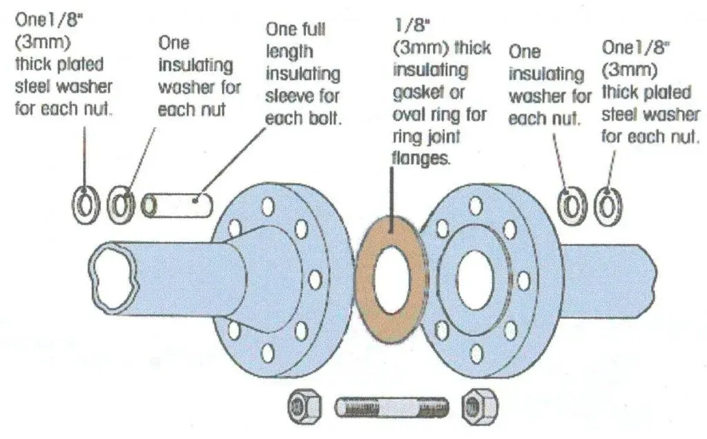
The insulating gasket is the primary barrier between the flange faces. It must seal against the process fluid while maintaining dielectric properties under compression. The insulating sleeves are tubes that slide over each stud bolt, filling the annular gap between the bolt and the flange bore. The insulating washers sit under the bolt head and nut, preventing electrical contact at those bearing surfaces. The steel backup washers sit between the insulating washer and the flange face (or between the insulating washer and the nut/bolt head) to distribute the clamping load and prevent the softer insulating washer from being crushed or extruded.
Applications
| Application | Purpose |
|---|---|
| Cathodic protection systems | Isolates pipeline sections for effective CP system operation |
| Dissimilar metal connections | Prevents galvanic corrosion between anodic and cathodic metals |
| Metering and custody transfer stations | Isolates metering skids from pipeline CP systems |
| Underground-to-aboveground transitions | Prevents CP current from draining into plant steelwork |
| Corrosive environments | Protects against electrochemical corrosion in chemical plants and offshore facilities |
| Marine and offshore risers | Isolates subsea pipework from topside equipment |
Types of Flange Isolation Kits
Four kit types are designated by the gasket style and the flange face configuration they fit:
| Type | Flange Face | Application | Gasket Style |
|---|---|---|---|
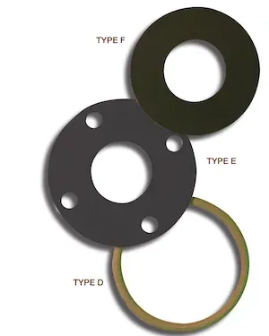
| F | FF / RF | General service, basic isolation | Full-faced gasket covering entire flange face |
| E | RF | Elevated P/T, oil & gas, chemical | Ring gasket with enhanced sealing |
| D | RTJ | High P/T, offshore, marine, underground | Gasket fits RTJ groove |
| O | Orifice | Flow measurement systems | Ring or full-face with extra sealing elements |
Type F (FF/RF Flanges)
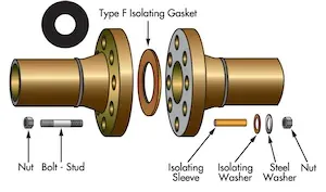
Type F kits fit flat-face and raised-face flanges, the most common configurations in industrial piping. The full-face gasket extends to the bolt circle with holes for each bolt, covering the entire flange face. The gasket OD is smaller than the flange OD. Special band protectors can be added to prevent foreign material accumulation between the flange faces.
Gasket materials: 1/8” thick fabric-based phenolic (plain or nitrile-coated), non-asbestos fibers with high dielectric capacity.
Benefits: Versatile for oil & gas, chemical, and water treatment; full-faced design simplifies installation and alignment. The large contact area provides good stability and centering.
Pressure/temperature range: Suitable for most general-service applications. For elevated pressure and temperature, Type E kits provide better sealing performance on RF flanges.
Type E (RF Flanges)
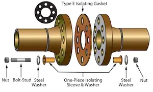
Type E kits fit raised-face flanges only, with the gasket covering the raised face portion. The ring gasket concentrates compression over the critical sealing area and keeps foreign material outside the joint. Elastomeric seal rings (Viton, Buna-N, or PTFE) can be incorporated into the gasket for enhanced sealing in sour or hazardous service.
Gasket materials: G10/G11 laminate, phenolic, neoprene-faced phenolic, and high-temperature materials.
Benefits: Precise alignment on RF flanges; concentrated gasket stress for better sealing. Effective for oil & gas, chemical, and water treatment where elevated P/T requires enhanced sealing.
Type D (RTJ Flanges)
Type D kits are designed for ring-type joint (RTJ) flanges used in high-pressure and high-temperature applications. The gasket fits within the RTJ groove, providing both sealing and electrical isolation. The groove geometry constrains the gasket, resulting in excellent containment under high pressure.
Gasket materials: Phenolic laminate with elastomer seals, G10/G11 laminate.
Applications: Oil & gas, petrochemical, power generation where high P/T conditions require RTJ flanges. Critical for subsea, offshore, and underground installations where dissimilar metals meet.
Type O (Orifice Flanges)
Orifice flanges used in flow measurement systems require Type O kits. The gasket features extra sealing elements (PTFE, Nitrile, or Viton) on both sides and is available in ring (E-style) or full-face (F-style) designs.
Gasket materials: Phenolic, G-10. Sleeve materials: Polyethylene, phenolic.
Applications: Oil & gas extraction, refining, and chemical processing where accurate flow measurement requires electrical isolation to maintain meter accuracy and prevent galvanic corrosion.
Selection Criteria
| Factor | Consideration |
|---|---|
| Flange face type | FF, RF, or RTJ determines kit type (F, E, or D) |
| Operating conditions | Temperature, pressure, corrosive environment |
| Electrical isolation | Level needed for galvanic protection or CP system |
| Material compatibility | Match to flange, pipeline, and process fluid |
| Service type | Sour service (NACE MR0175), chemical, subsea |
Flange Isolation Kit Materials
Material selection depends on dielectric strength, temperature limits, water absorption, and chemical compatibility with the process fluid. Low water absorption is critical: absorbed moisture creates conductive paths that compromise isolation over time.
Gasket Material Comparison
| Gasket Material | Dielectric Strength (V/mil) | Max. Temperature | Water Absorption | Best For |
|---|---|---|---|---|
| G10/G11 (NEMA) | UL94 VO rated | 200 C (392 F) | 0.01% | General service, sour gas, offshore |
| Plain Phenolic | 500 | 107 C (225 F) | 1.10% | Moderate service, economical |
| Neoprene-faced Phenolic | 500 | 80 C (175 F) | 0.45% | Low-temperature, water service |
| PTFE (Teflon) | 600 | 232 C (450 F) | 0.01% | Chemical service, corrosive fluids |
| Garlock 3400 | 630 | 371 C (700 F) | — | High-temperature service |
| Klinger C4401 | 300 | 399 C (750 F) | — | High-temperature service |
| JM940 Red Devil | 2400 | 371 C (700 F) | — | High dielectric strength |
| Insul-Seal | 500 | 80 C (175 F) | 0.50% | General service |
| Phenolic RTJ Type D | 500 | 107 C (225 F) | 1.00% | RTJ flanges |
Insulating Sleeves
| Sleeve Material | Dielectric Strength (V/mil) | Max. Temperature | Water Absorption |
|---|---|---|---|
| Mylar | 4000 | 177 C (350 F) | 0.22% |
| NEMA G10 | UL94VO | FR rated | 0.01% |
| Phenolic | 500 | 121 C (250 F) | 2.00% |
| Minlon | 450 | 149 C (300 F) | 0.90% |
Mylar sleeves offer the highest dielectric strength (4000 V/mil), making them the preferred choice for critical applications. G10 fiberglass sleeves provide the best combination of mechanical strength and low water absorption for demanding environments.
Insulating Washers
| Washer Material | Dielectric Strength (V/mil) | Max. Temperature | Water Absorption |
|---|---|---|---|
| NEMA G11 | UL94VO | FR rated | 0.01% |
| PTFE | 600 | 232 C (450 F) | 0.01% |
| Phenolic | 500 | 107 C (225 F) | 1.10% |
| Non-Asbestos | 300 | 399 C (750 F) | — |
Steel Backup Washers
Steel backup washers (galvanized carbon steel or stainless steel) distribute bolt load and protect the softer insulating washers from damage during bolt tightening. They are not optional; omitting them is the most common installation mistake.
Where to Install Isolation Kits
Isolation kits must be installed at specific locations in a piping system to maintain the integrity of cathodic protection and prevent galvanic corrosion. The following locations are typical:
| Installation Point | Reason |
|---|---|
| Pipeline entry to plant/facility | Prevents CP current from draining into plant steelwork |
| Buried-to-aboveground transition | Isolates cathodically protected buried pipe from unprotected above-ground pipe |
| Dissimilar metal flanged joints | Breaks the galvanic circuit between carbon steel and alloy/stainless components |
| Metering stations | Isolates custody transfer metering from pipeline CP and stray currents |
| Pipeline crossings | Prevents CP interference between parallel or crossing pipelines |
| Platform risers (offshore) | Isolates subsea cathodically protected pipe from topside equipment |
| Storage tank connections | Isolates tank CP system from incoming/outgoing piping |
Testing Flange Isolation Kits
Post-installation testing is mandatory to confirm that the isolation kit is functioning correctly. A kit that looks properly installed may still have a hidden metallic bridge from a misaligned sleeve, conductive debris, or a cracked washer.
Resistance Testing
The primary test method is measuring electrical resistance across the isolated joint using a digital multimeter:
- Set the multimeter to the megaohm range
- Place one probe on the upstream flange and the other on the downstream flange
- Acceptable: Resistance above 1 megaohm indicates effective isolation
- Unacceptable: Resistance below 1 megaohm indicates a metallic bridge
If resistance is low, inspect for:
- Bolt sleeves that have shifted or split, allowing the bolt to contact the flange bore
- Conductive debris (mill scale, weld spatter, dirt) between the flange faces
- Cracked or crushed insulating washers
- Missing steel backup washers (causing washer extrusion and metal contact)
Holiday Detection
For critical installations, holiday detection (spark testing) can be used to verify the integrity of insulating coatings on the gasket and sleeves before assembly. A high-voltage, low-amperage probe is passed over the insulating surface. Any spark indicates a pinhole or defect that could compromise isolation.
Ongoing Monitoring
Isolation kits should be re-tested periodically, especially in buried or submerged installations where moisture ingress can degrade dielectric properties over time. Annual testing is standard practice for cathodic protection systems per NACE SP0169.
Common Installation Mistakes
The following mistakes account for the majority of isolation kit failures:
| Mistake | Consequence | Prevention |
|---|---|---|
| Missing steel backup washers | Insulating washers crush under bolt torque, creating metal-to-metal contact | Always include backup washers; they distribute the bolt load |
| Misaligned bolt sleeves | Bolt contacts flange bore, creating a conductive bridge | Center each bolt carefully; verify sleeve extends full bore length |
| Conductive debris on flange faces | Foreign material bridges the insulating gasket | Clean both flange faces thoroughly before assembly |
| Anti-seize on insulating components | Metallic anti-seize creates conductive paths across insulating surfaces | Apply anti-seize to bolt threads only; keep off sleeves and washers |
| Uneven bolt torquing | Gasket distortion, uneven compression, potential leak and isolation loss | Torque in star pattern per ASME PCC-1 |
| Wrong kit type for flange face | Gasket does not seat properly, fails to seal or isolate | Match kit type (F, E, D) to the flange face (FF, RF, RTJ) |
| Not testing after installation | Hidden metallic bridge goes undetected until CP system fails | Always measure resistance across the joint before commissioning |
| Reusing old isolation kits | Degraded dielectric properties from compression set, moisture absorption, or damage | Install new kits; never reuse gaskets, sleeves, or washers |
Temperature and Pressure Limitations
Isolation kit performance is limited by the weakest component in the assembly. The maximum allowable working pressure follows the flange pressure-temperature rating per ASME B16.5 or B16.47, but the gasket material imposes additional temperature limits.
| Material | Max. Temperature | Max. Pressure | Typical Service |
|---|---|---|---|
| G10/G11 laminate | 200 C (392 F) | Per flange rating | Oil & gas, offshore, sour service |
| Phenolic | 107 C (225 F) | Per flange rating | Water treatment, moderate chemical |
| PTFE | 232 C (450 F) | Per flange rating (watch cold flow) | Chemical, corrosive service |
| Garlock 3400 | 371 C (700 F) | Per flange rating | High-temperature refinery service |
| Non-asbestos fiber | 399 C (750 F) | Per flange rating | High-temperature utility service |
Availability: ASME B16.5, B16.47, and API flanges from 1/2” to 80”. Standard sizes up to 24”; larger sizes available on request.
Standards and Specifications
| Standard | Scope |
|---|---|
| NACE SP0286 | Electrical isolation of cathodically protected pipelines; the primary standard for isolation kit selection and testing |
| ASTM F2836 | Standard practice for gaskets for use in connection with flange isolation kits |
| NACE SP0169 | Control of external corrosion on underground or submerged metallic piping systems (CP design) |
| NACE MR0175 / ISO 15156 | Material requirements for sour service (H2S environments) |
| ASME B16.5 | Pipe flanges and flanged fittings (dimensions that isolation kits must fit) |
| ASME B16.47 | Large diameter steel flanges (NPS 26 through NPS 60) |
| ASME PCC-1 | Guidelines for pressure boundary bolted flange joint assembly (torque procedures) |
| EN ISO 26623 | Flange isolation gaskets (European standard) |
Frequently Asked Questions
What is a flange isolation kit and what does it do?
A flange isolation kit is a set of components (insulating gasket, bolt sleeves, insulating washers, and steel backup washers) installed at a bolted flange joint to electrically isolate the two flanges from each other. It prevents galvanic corrosion and preserves cathodic protection systems by breaking the electrical path across the joint. Without isolation, current flows through the metal-to-metal contact at the flange faces, bolt holes, and bolt/nut bearing surfaces.
When is a flange isolation kit required?
Flange isolation kits are required wherever cathodic protection systems must be preserved (buried or subsea pipelines connecting to above-ground equipment), at dissimilar metal connections (e.g., carbon steel to stainless steel), at pipeline metering and custody transfer stations, at underground-to-aboveground transitions, and in offshore and marine environments where corrosion protection of risers and platform piping is critical.
What is the difference between Type E, Type F, and Type D isolation kits?
Type F kits use a full-face gasket for flat-face and raised-face flanges and are suitable for general service. Type E kits use a ring gasket sized to cover only the raised face of RF flanges, providing better sealing at elevated pressure and temperature. Type D kits have a gasket that fits the RTJ groove for ring-type joint flanges, used in high-pressure and high-temperature service such as offshore and subsea installations.
How do you test a flange isolation kit after installation?
After installation, measure electrical resistance across the joint with a digital multimeter set to the megaohm range. A properly isolated joint should read at least 1 megaohm. Readings below 1 megaohm indicate a metallic bridge, typically caused by a missing or damaged sleeve, misaligned washer, or conductive debris between the flange faces. Testing should be performed before commissioning and repeated annually for cathodic protection systems.
What gasket material should I choose for a flange isolation kit?
G10/G11 fiberglass laminate is the most common choice for general and oil & gas service (up to 200 C) due to excellent dielectric strength and very low water absorption (0.01%). Phenolic is more economical for moderate temperatures (up to 107 C). PTFE handles chemical and corrosive service up to 232 C but is susceptible to cold flow under sustained load. For sour gas (H2S) service per NACE MR0175, use Type E or Type F kits with PTFE sealing elements and G10/G11 laminate gaskets.
Leave a Comment
Have a question or feedback? Send us a message.
Previous Comments
Such a nice content because it is fuul of information.
Pretty good content,helped me understand what's in these kits so I can do BOM's for my projects without worry.Keep up the good work!
I highly suggest consulting a sales person at a manufacturer before specifying these. Avoid Phenolic/Micarta and Minlon at all costs. It will break at some point and render the kit useless. G10 is what is needed at a minimum, which is crosswoven glass reinforced epoxy. Very strong fiberglass 1/8″ thk. Teflon or Viton seal for O&G applications.
¿Where to ordere this kists? Thank you Fran
I needed insulating kit for 6 inch 600 class RF flanges.i needed supplier for it in Pakistan