Ductile Iron Pipe: Sizes & Specs
Ductile Iron Pipes
What Are Ductile Iron Pipes
Ductile iron pipes combine high tensile strength, good ductility, and long service life in a single product. The base material is ductile cast iron, which tolerates significant internal and external pressures without cracking. Primary service areas include water and wastewater systems, gas distribution, and industrial process piping.
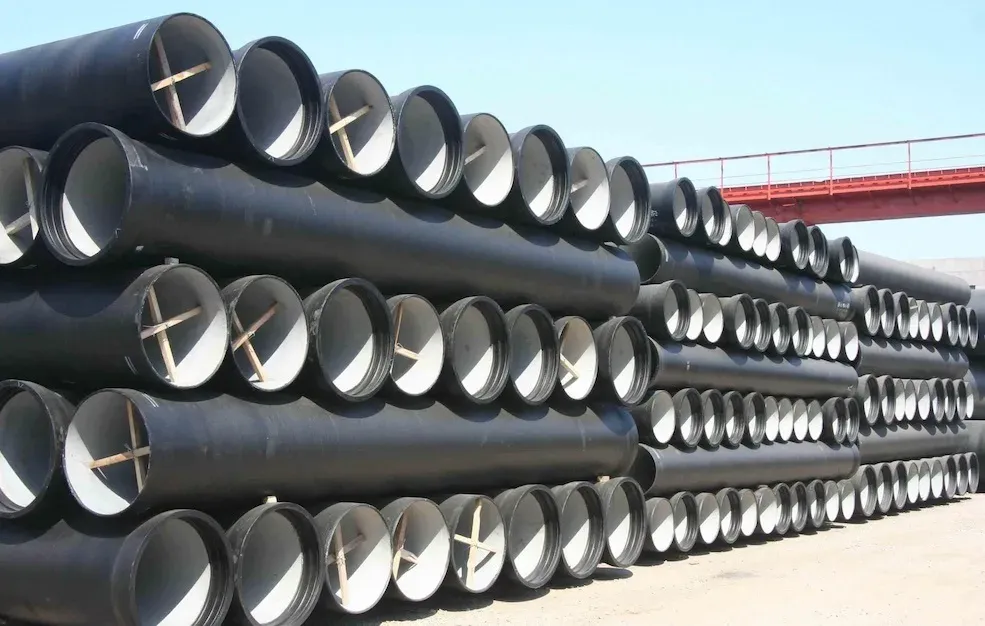
The pipes are manufactured by centrifugal casting, then annealed to improve mechanical properties. Standard production includes internal linings (cement mortar, polyurethane, epoxy) and external coatings (zinc, bitumen, polyethylene sleeve) for corrosion resistance and water quality protection. Available sizes range from DN 80 through DN 2000 in standard laying lengths.
The joint systems (push-on, mechanical, flanged, restrained) allow fast field assembly and accommodate ground settlement, thermal movement, and angular deflection. At end of life, ductile iron is fully recyclable, which supports circular-economy objectives in infrastructure projects.
What Is Ductile Iron
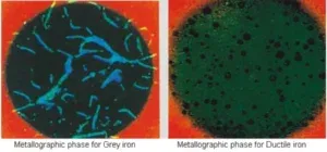
The microstructure contains nodular (spheroidal) graphite inclusions within a ferritic or pearlitic matrix. This structure results from adding magnesium or cerium to the molten iron during treatment. The spheroidal graphite shape gives the material the ability to bend and deform under load rather than fracturing, which distinguishes it from conventional grey cast iron.
 Ductile iron vs cast iron
Applications of Ductile Iron Pipes
Ductile iron pipes serve a broad range of infrastructure and industrial systems:
| Application | Details |
|---|---|
| Water Supply and Distribution | Strong pressure and impact resistance for water mains, distribution lines, and pumping stations. |
| Sewer and Wastewater Systems | Used in gravity and pressure sewer systems, with high resistance to wear and corrosion from sewage. |
| Gas Distribution | High joint integrity and tensile strength support safe transport of natural gas. |
| Industrial Applications | Process piping for liquids, gases, and slurries across chemical, mining, and power-generation facilities. |
Across all these services, ductile iron pipes remain a dominant choice because they deliver strength, ductility, and a 100+ year design life in a single product. Their track record in municipal water systems and industrial plants reflects decades of proven field performance.
Advantages/disadvantages Of Ductile Iron Pipes
Advantages
| Advantage | Description |
|---|---|
| Strength and Durability | High tensile strength and the ability to withstand significant internal and external pressures, reducing the risk of cracks and failures. |
| Flexibility and Impact Resistance | Unlike rigid pipe materials, ductile iron can flex under loads, resisting impact damage during installation and accommodating ground movement in service. |
| Corrosion Resistance | With proper coatings and linings, ductile iron pipes provide excellent resistance to both internal and external corrosion, extending service life well beyond 100 years. |
| Ease of Installation | Push-on and mechanical joints allow fast, reliable field assembly without specialized tools, reducing project timelines and labor costs. |
| Sustainability | Ductile iron is 100% recyclable at end of service life, and recycled scrap iron is a standard feedstock in production. |
Disadvantages
| Disadvantage | Description |
|---|---|
| Corrosion Protection | Depending on soil and water chemistry, additional protection (polyethylene encasement, cathodic protection) may be required beyond the standard zinc coating. |
| Weight | Ductile iron pipes are heavier than HDPE, PVC, or GRP alternatives, which increases handling equipment requirements and transport costs. |
| Regular Inspection | Routine inspection and maintenance are necessary to verify coating integrity and joint performance over the pipeline’s service life. |
Manufacturing Process
Ductile iron pipe production follows four stages:
| Step | Process | Details |
|---|---|---|
| 1 | Melting and Treatment | Iron, scrap steel, and additives are melted in a furnace. The molten iron is then treated with magnesium (or cerium) to convert graphite from flake to spheroidal form, which produces the material’s ductility. |
| 2 | Casting | The treated melt is poured into rotating molds (centrifugal casting), producing pipes with uniform wall thickness and high density. |
| 3 | Annealing | After casting, the pipes undergo heat treatment to further improve ductility and relieve internal stresses from the casting process. |
| 4 | Finishing | Pipes are cooled, cleaned, and receive their internal lining (cement mortar, epoxy, or polyurethane) and external coating (zinc plus bitumen topcoat, or polyethylene) for corrosion protection. |
The production process is shown in this video (Source: McWane Ductile)
@supports not (aspect-ratio:1/1){}@supports not (aspect-ratio:1/1){}
Ductile Iron Pipe Dimensions
Ductile iron pipe dimensions follow American (ANSI/AWWA) and European (EN) standards. Each standard defines diameters, wall thicknesses, pressure classes, and tolerances that govern pipe selection for a given application.
The tables below summarize the primary dimensions and thicknesses under both systems.
American Specs (ANSI/AWWA C151)
OD/ID, WT/Class
ANSI/AWWA C151/A21.51 covers ductile iron pipes for water and other liquids. The key dimensional parameters are:
| Parameter | Details |
|---|---|
| Diameter | Nominal sizes from 3 inches (76 mm) to 64 inches (1,626 mm). |
| Thickness Class | Class 50 through Class 56 for pipes up to 24 inches in diameter. Each class corresponds to a different wall thickness rated for specific internal pressure and external load combinations. |
| Pressure Class | Ranges from 150 psi (1,034 kPa) to 350 psi (2,413 kPa), representing the maximum allowable operating pressure. |
| Inside Diameter (UNL/CL/DCL) | Varies with lining type: UNL = unlined (bare iron), CL = cement lined, DCL = double cement lined. |
Note that:
- ANSI/AWWA C151/A21.51: American standard for ductile iron pipes for water and other liquids.
- ANSI/AWWA C115/A21.15: For flanged ductile iron pipes.
The following size chart shows dimensions and weights for ductile iron water transmission pipe (NPS 3” to 54”, Class 53, the most common class for water applications):
| NPSinch. | NPS mm | OD inch. | OD mm | Class | WT inch. | Weight in Lb/ft | Weight with Water Lb/ft |
|---|---|---|---|---|---|---|---|
| 3″ | 80.00 | 3.96 | 100.60 | 53.00 | 0.31 | 11.20 | 15.00 |
| 4″ | 100.00 | 4.80 | 121.90 | 53.00 | 0.32 | 14.20 | 20.10 |
| 6″ | 150.00 | 6.90 | 175.30 | 53.00 | 0.34 | 22.00 | 35.10 |
| 8″ | 200.00 | 9.05 | 229.90 | 53.00 | 0.36 | 31.00 | 54.00 |
| 10″ | 250.00 | 11.10 | 281.90 | 53.00 | 0.38 | 40.40 | 76.80 |
| 12″ | 300.00 | 13.20 | 335.20 | 53.00 | 0.40 | 50.70 | 103.00 |
| 14″ | 350.00 | 15.30 | 388.60 | 53.00 | 0.42 | 62.40 | 133.50 |
| 16″ | 400.00 | 17.40 | 442.00 | 53.00 | 0.43 | 72.80 | 165.90 |
| 18″ | 450.00 | 19.50 | 495.30 | 53.00 | 0.44 | 83.60 | 201.50 |
| 20″ | 500.00 | 21.60 | 548.60 | 53.00 | 0.45 | 95.20 | 241.00 |
| 24″ | 600.00 | 25.80 | 655.30 | 53.00 | 0.47 | 119.20 | 329.40 |
| 30″ | 750.00 | 32.00 | 812.80 | 53.00 | 0.51 | 161.30 | 487.80 |
| 36″ | 900.00 | 38.30 | 972.80 | 53.00 | 0.58 | 219.50 | 688.80 |
| 42″ | 1050.00 | 44.50 | 1130.30 | 53.00 | 0.65 | 285.20 | 920.10 |
| 48″ | 1200.00 | 50.80 | 1290.30 | 53.00 | 0.72 | 360.30 | 1189.20 |
| 54″ | 1350.00 | 57.10 | 1450.30 | 53.00 | 0.81 | 455.00 | 1502.20 |
Pipe Lengths (ANSI/AWWA)
Under ANSI/AWWA C151/A21.51, ductile iron pipes are supplied in the following lengths:
| Length Type | Dimension | Notes |
|---|---|---|
| Standard laying length | 18 ft (5.5 m) or 20 ft (6.1 m) | Main body length, excludes joint/bell length |
| Custom lengths | Per project specification | Available from most manufacturers when non-standard lengths are required for alignment or tie-in purposes |
European Specs (EN 545/598)
OD/ID, WT/Class
EN 545 (water pipelines) and EN 598 (sewerage) govern ductile iron pipe dimensions in Europe:
| Parameter | Details |
|---|---|
| Diameter | Nominal sizes from DN 40 (40 mm) to DN 2000 (2,000 mm). |
| Wall Thickness | Specified per diameter and class combination. Unlike AWWA, EN standards assign explicit wall thickness values for each size/class pair. |
| Class Designation | Pipes are classified by allowable operating pressure. Standard classes include C40, C30, and C25, where the number is the nominal pressure in bars (C40 = 40 bar). |
| DN | OD (mm/inch.) | WT Class 40 (mm/inch.) | WT K9 (mm/inch.) | WT K10 (mm/inch.) |
|---|---|---|---|---|
| 40 | 56 (2.205) | 4.8 (0.189) | 6.0 (0.236) | 6.0 (0.236) |
| 50 | 66 (2.598) | 4.8 (0.189) | 6.0 (0.236) | 6.0 (0.236) |
| 60 | 77 (3.031) | 4.8 (0.189) | 6.0 (0.236) | 6.0 (0.236) |
| 65 | 82 (3.228) | 4.8 (0.189) | 6.0 (0.236) | 6.0 (0.236) |
| 80 | 98 (3.858) | 4.8 (0.189) | 6.0 (0.236) | 6.0 (0.236) |
| 100 | 118 (4.646) | 4.8 (0.189) | 6.0 (0.236) | 6.0 (0.236) |
| 125 | 144 (5.669) | 4.8 (0.189) | 6.0 (0.236) | 6.0 (0.236) |
| 150 | 170 (6.693) | 5.0 (0.197) | 6.0 (0.236) | 6.5 (0.256) |
| 200 | 222 (8.740) | 5.4 (0.213) | 6.3 (0.248) | 7.0 (0.276) |
| 250 | 274 (10.787) | 5.8 (0.228) | 6.8 (0.268) | 7.5 (0.295) |
| 300 | 326 (12.835) | 6.2 (0.244) | 7.2 (0.283) | 8.0 (0.315) |
| 350 | 378 (14.882) | 7.0 (0.276) | 7.7 (0.303) | 8.5 (0.335) |
| 400 | 429 (16.890) | 7.8 (0.307) | 8.1 (0.319) | 9.0 (0.354) |
| 450 | 480 (18.898) | - | 8.6 (0.339) | 9.5 (0.374) |
| 500 | 532 (20.945) | - | 9.0 (0.354) | 10.0 (0.394) |
| 600 | 635 (25.000) | - | 9.9 (0.390) | 11.1 (0.437) |
| 700 | 738 (29.055) | - | 10.9 (0.429) | 12.0 (0.472) |
| 800 | 842 (33.150) | - | 11.7 (0.461) | 13.0 (0.512) |
| 900 | 945 (37.205) | - | 12.9 (0.508) | 14.1 (0.555) |
| 1000 | 1,048 (41.260) | - | 13.5 (0.531) | 15.0 (0.591) |
| 1100 | 1,152 (45.354) | - | 14.4 (0.567) | 16.0 (0.630) |
| 1200 | 1,255 (49.409) | - | 15.3 (0.602) | 17.0 (0.669) |
| 1400 | 1,462 (57.559) | - | 17.1 (0.673) | 19.0 (0.748) |
| 1500 | 1,565 (61.614) | - | 18.0 (0.709) | 20.0 (0.787) |
| 1600 | 1,668 (65.669) | - | 18.9 (0.744) | 51.0 (2.008) |
| 1800 | 1,875 (73.819) | - | 20.7 (0.815) | 23.0 (0.906) |
| 2000 | 2,082 (81.969) | - | 22.5 (0.886) | 25.0 (0.984) |
Both American and European specifications provide the dimensional framework that manufacturers and engineers rely on when selecting ductile iron pipe for a given service. Always reference the latest edition of each standard, as revisions may change specific requirements.
The choice between American and European standards typically depends on the project location, owner specifications, and local regulatory requirements.
K8, K9, K10 Classes (EN 545)
The K8, K9, K10 designations refer to wall thickness classes for ductile iron pipes under ISO 2531 and EN 545. The “K” value is a coefficient used in the wall thickness formula; a higher K number produces a thicker wall and greater pressure/load capacity.
Understanding K Classes
The “K” number does not directly state a pressure rating in bar or psi. Instead, it defines the wall thickness as a function of diameter using the formulas in ISO 2531 and EN 545. Thicker walls mean higher allowable internal pressure and greater resistance to external loads (traffic, soil, groundwater).
The wall thickness for a given K class is calculated from the pipe’s nominal diameter and the K coefficient. This calculation builds in a safety margin above the expected operating pressure.
Common Classes and Applications
| K Class | Typical Application |
|---|---|
| K8 | Lower-pressure systems or stable ground conditions with minimal external loading. |
| K9 | The standard class for municipal water supply and distribution networks. Provides a practical balance of wall thickness and cost. |
| K10 and Above | Higher-pressure service or heavy external loading: deep burial, heavy traffic, or unstable soils. |
Selection Criteria
Selecting the right K class requires evaluating operating pressure, fluid type, burial depth, soil conditions, and traffic/surface loads. Compliance with local codes and the project’s design life also factor into the decision. In practice, K9 covers most municipal water applications, while K10+ is specified when the design pressure or external load demands it.
Differences between C-Class and K-Class in EN545
The “C” and “K” designations in EN 545 address pipe capability from two different angles:
| Aspect | C-Class (C30, C40, etc.) | K-Class (K8, K9, etc.) |
|---|---|---|
| What it specifies | The nominal pressure rating. The number after “C” is the allowable pressure in bars (C30 = 30 bar, C40 = 40 bar). | The wall thickness coefficient used in a formula based on pipe diameter. Higher K = thicker wall. |
| Pressure indication | Direct: the class number equals the pressure rating in bars. | Indirect: wall thickness correlates with pressure capacity, but the relationship depends on diameter. |
| Design focus | Pressure endurance of the pipe system. | Structural robustness against both internal pressure and external mechanical loads. |
| Typical usage | Specified when a defined pressure rating is the primary selection criterion. | Common in general water supply specifications derived from ISO 2531. |
Pipe Lengths (EN 545)
EN 545 (water) and EN 598 (sewerage) define the following standard lengths:
| Length Type | Dimension | Notes |
|---|---|---|
| Standard length | 6 m (19.7 ft) | Tolerance varies by manufacturer |
| Short lengths | 1 m (3.3 ft) to 3 m (9.8 ft) | Used for fittings, tie-ins, and route adjustments |
Other Specifications for Ductile Iron Pipes
- International Standard: ISO2531-2009
- UK Standard: BS EN545-2002
- China: GB/T13295-2003
- South Korean Standard: KSD 4311
- Australian Standard: AS 2280
Pipe Connection Types
The joint type determines installation speed, movement accommodation, and long-term pipeline integrity. The following sections cover each common joint type used with ductile iron pipes.
Push-on (tyton) Joints
 Push-on (Tyton) joint ductile iron pipe installation
Push-on joints (also called Tyton or slip joints) use a rubber gasket seated in the bell (female end). The spigot (male end) of the next pipe is pushed into the bell, compressing the gasket to form the seal. No special tools are required, and the joint allows slight angular deflection and axial movement to accommodate ground settlement. Push-on joints are the standard choice for water and wastewater mains operating at moderate pressures.
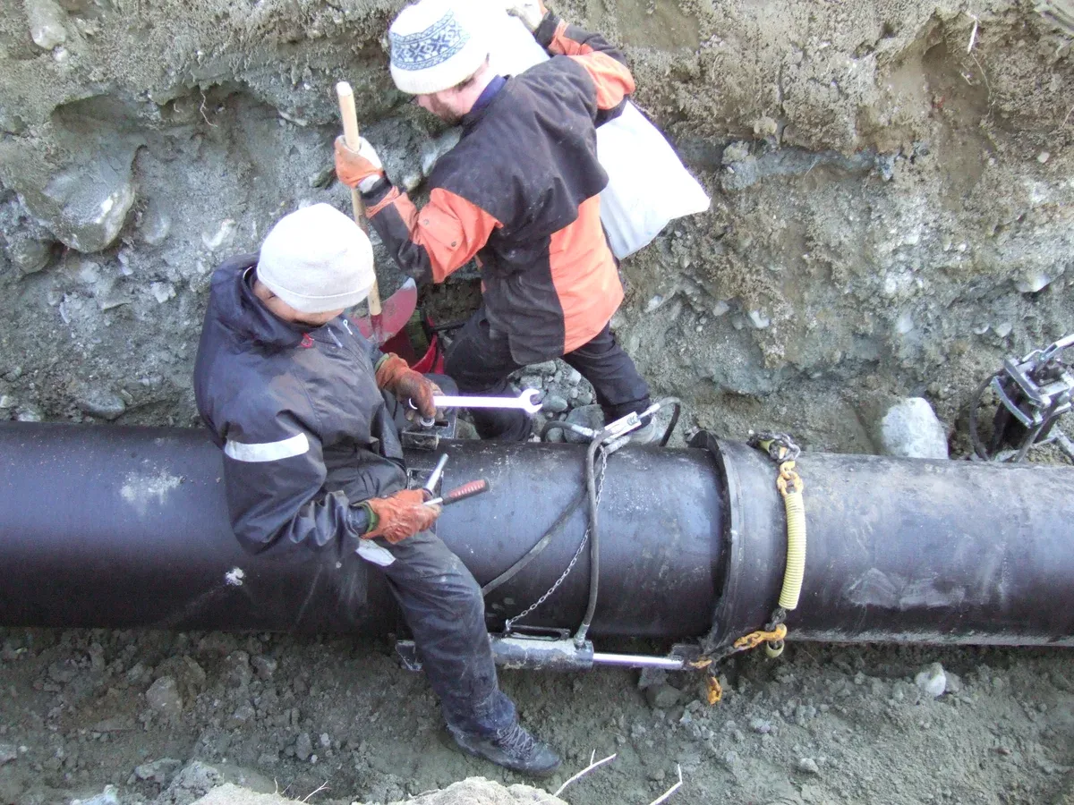
Mechanical Joints
 Mechanical joint for ductile iron pipes
A mechanical joint consists of a follower gland, rubber gasket, and a set of bolts and nuts. The spigot inserts into the bell, the gasket seats against the spigot, and the gland compresses the gasket when the bolts are tightened. This design permits alignment adjustment during assembly and allows disassembly for future maintenance. Mechanical joints serve both water and gas distribution systems, particularly where periodic reconfiguration or valve replacement is anticipated.
Flanged Joints
Flanged joints bolt two pipe-end flanges together with a gasket between the faces. The connection is rigid and fully restrained, which makes it well suited for connections to pumps, valves, meters, and other equipment. Disassembly is straightforward, so flanged joints are the standard at treatment plants, pump stations, and anywhere the pipeline requires periodic inspection or equipment removal.
Restrained Joints
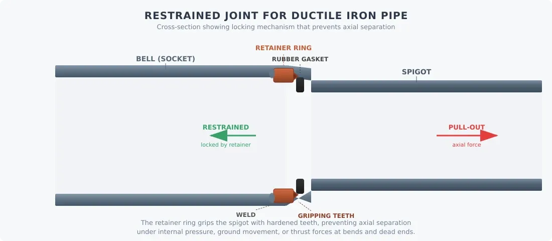 Restrained joint for ductile iron pipes
Restrained joints add a locking mechanism (welded retainer rings, weld-on lugs, or gripping devices) to a push-on or mechanical joint to resist axial pullout forces. They eliminate the need for thrust blocks at bends, tees, and dead ends. Restrained joints are specified on sloped terrain, in flood-prone areas, at directional changes, and wherever high internal pressure or external forces could separate a standard joint.
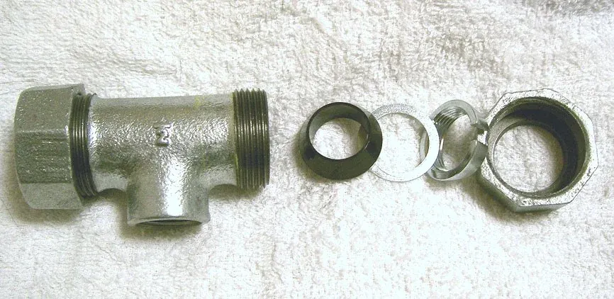
Grooved/coupled Joints
Grooved joints use a circumferential groove rolled or cut into the pipe ends. A two-piece coupling clamps over the grooves with a rubber gasket inside to provide the seal. Assembly and disassembly are fast, and the coupling permits some angular and axial movement. Grooved joints are common in fire protection systems, HVAC, and industrial piping where the system may need future modification.
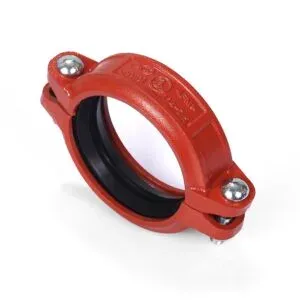 Grooved Couple Joint for Ductile Pipes
Material Grades
Ductile iron pipe grades are defined by ASTM, ISO, and EN standards. The grades differ in tensile strength, yield strength, elongation, and hardness, with some specialty grades adding alloying elements for enhanced corrosion resistance or impact toughness.
Common Grades
ISO 2531 & EN 545/EN 598 Grades
| Grade | Tensile Strength | Typical Application |
|---|---|---|
| EN-GJS-400-15 | Min. 400 MPa | Excellent ductility; commonly used in water and wastewater applications. |
| EN-GJS-450-10 | Min. 450 MPa | Good balance between strength and ductility; suitable for higher-pressure applications. |
| EN-GJS-500-7 | Min. 500 MPa | Used in sewage applications; offers increased strength and wear resistance. |
| EN-GJS-600-3 | Min. 600 MPa | Highest strength grade commonly used for ductile iron pipes; specified for high-pressure and industrial service. |
ASTM A536 Grades
| Grade | Tensile Strength | Typical Application |
|---|---|---|
| 60-40-18 | 414 MPa | Outstanding ductility and impact resistance; comparable to EN-GJS-400-15. |
| 65-45-12 | 448 MPa | Balance of strength and ductility; general-purpose grade. |
| 80-55-06 | 552 MPa | Higher strength with moderate ductility. |
| 100-70-03 | 689 MPa | Highest strength in ASTM A536 with lower ductility; used where maximum strength is the priority. |
Specialty Grades
Some manufacturers produce grades outside the standard classifications for specific service conditions:
- High impact resistance grades: Developed for seismically active regions or pipes subject to heavy traffic loads.
- Corrosion-resistant grades: Alloyed with copper, nickel, or chromium for enhanced resistance in aggressive soils or fluids.
How to Choose the Right Grade
Grade selection depends on the transported fluid, operating pressure, burial conditions, and project design life. In most municipal water applications, EN-GJS-400-15 or ASTM 60-40-18 provides adequate strength with maximum ductility. Higher-strength grades (EN-GJS-500-7, ASTM 80-55-06) are reserved for sewage, industrial, or high-pressure service where wear resistance or higher working pressures drive the specification.
Corrosion of Ductile Iron Pipes
Corrosion is the primary threat to ductile iron pipe longevity, affecting both structural integrity and water quality. Corrosion mechanisms and available countermeasures matters for specifying the correct protection system.
Mechanisms of Corrosion
| Mechanism | Description |
|---|---|
| Galvanic Corrosion | Occurs when ductile iron contacts a more noble metal (e.g., copper) in the presence of an electrolyte, accelerating iron dissolution. |
| Pitting Corrosion | Localized attack that creates small holes or pits on the pipe surface. Typically driven by chlorides and low-pH water. |
| Microbiologically Influenced Corrosion (MIC) | Certain bacteria produce corrosive by-products (sulfides, organic acids) that accelerate local corrosion rates. |
| Graphitic Corrosion | Selective leaching of iron from the ductile iron matrix, leaving behind a weak graphite residue with little structural capacity. |
Effects of Corrosion
| Effect | Description |
|---|---|
| Reduced Pipe Life | Wall loss from corrosion leads to premature failure and unplanned replacement. |
| Decreased Water Quality | Corrosion by-products (iron oxides, turbidity) degrade taste, color, and safety of the water supply. |
| Increased Maintenance Costs | Corroded sections require more frequent repair, leak detection, and eventually full replacement. |
Corrosion Mitigation Strategies
| Strategy | Description |
|---|---|
| Cathodic Protection | A sacrificial anode or impressed-current system redirects corrosive activity away from the pipe, protecting the iron at the expense of the anode material. |
| Coatings and Linings | External zinc coating (galvanic protection) plus bitumen or polymer topcoat. Internal cement-mortar or epoxy lining prevents contact between the water and the pipe wall. |
| Control of Water Chemistry | Adjusting pH and limiting aggressive-ion concentrations (chlorides, sulfates) to reduce corrosion rates. |
| Corrosion Inhibitors | Chemical additives that form a protective film on the pipe interior, slowing the corrosion reaction. |
| Design Considerations | Minimizing dead legs, providing proper drainage, and avoiding direct contact with dissimilar metals all reduce corrosion risk at the design stage. |
| Regular Monitoring and Maintenance | Scheduled inspections (coupon testing, pipe-wall thickness surveys, water quality sampling) detect early corrosion so repairs can be made before failures occur. |
Lining & Coating For Ductile Iron Pipes
Internal linings and external coatings are the primary defense against corrosion in ductile iron pipe systems. They extend service life, maintain water quality, improve hydraulic performance, and reduce long-term maintenance costs.
Internal Linings
| Lining Type | Application | Benefits |
|---|---|---|
| Cement-Mortar Lining | Standard for potable water distribution. Protects against tuberculation (mineral deposit buildup) and is pH-neutral, which shields the pipe from aggressive waters. | Improves flow characteristics, reduces pumping energy, and limits bacterial growth on the pipe wall. |
| Polyethylene (PE) Lining | Used for pipes carrying aggressive chemicals, sewage, and industrial wastewater. | Provides strong chemical resistance, preventing internal attack from acids, alkalis, and solvents. |
| Epoxy Lining | Applied in both potable water and industrial systems where chemical resistance and a smooth bore are required. | Creates a durable, seamless, corrosion-resistant barrier with a low friction coefficient. |
| Polyurethane Lining | Specified for abrasive and highly corrosive service such as mining slurry and raw sewage. | Delivers high abrasion resistance and maintains integrity in harsh chemical environments. |
External Coatings
| Coating Type | Application | Benefits |
|---|---|---|
| Zinc Coating | The standard external treatment, typically finished with a bituminous paint or polymeric topcoat. | Functions as a sacrificial anode (galvanic protection), corroding preferentially to protect the iron substrate. |
| Polyethylene Encasement | Specified in aggressive soil conditions. A loose polyethylene sleeve wraps the pipe, creating a barrier between the iron and the soil. | Simple and inexpensive to apply; effective at preventing soil-driven corrosion. |
| Fusion-Bonded Epoxy Coating | A powder coating that melts and bonds to the pipe surface during application. Used for potable water and wastewater service. | Strong chemical resistance, UV stability, and excellent adhesion to the pipe surface. |
| Polyurethane Coating | Applied where the pipe faces highly corrosive soils, chemical exposure, or sustained UV radiation. | Superior impact, abrasion, and chemical resistance for long-term external protection. |

Leave a Comment
Have a question or feedback? Send us a message.