Gasket Types: SWG, RTJ & Metal
Pipe Gasket and Metal Gasket Types
What Is a Pipe Gasket?
A pipe gasket (also called flange gasket) is a sealing component designed to fit between two sections of pipe that are flanged together. Metal gaskets are used for high-pressure and high-temperature applications, while soft gaskets are suitable for lower service conditions.
Flanges are external or internal ridges that are used for strength or for the attachment of a component, like a pipe. The primary purpose of a flange gasket is to prevent leaks by providing a sealed interface between the two flange faces, ensuring no fluids or gases can escape from the flanged joint.
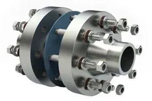 Gasket to Seal Flanges (Main & Companion)
Main Characteristics of Flange Gaskets
| Characteristic | Description |
|---|---|
| Material Composition | Flange gaskets are made from rubber, non-asbestos synthetic fibers, metal, silicone, PTFE, and graphite. The choice of material depends on fluid type, operating temperature, pressure conditions, and chemical compatibility. |
| Shape and Size | Typically circular to match flange shape, with bolt holes aligned to the flange pattern. Available in various sizes and thicknesses per ASME B16.5 or EN 1092-1. |
| Gasket Types | Flat/sheet gaskets (low-pressure), spiral-wound gaskets (high P/T), ring-type joints (high-pressure), cam profile and metal-jacketed gaskets (wide range of temperatures and pressures). All types are reviewed in detail in this article. |
| Sealing Function | Creates a tight seal between two flange faces, preventing fluid escape and maintaining piping system integrity. |
| Versatility | Used across oil and gas, chemical processing, power generation, and water treatment in pipelines, tanks, and vessels. |
| Pressure and Temperature Resistance | Different gasket materials and designs withstand various pressure and temperature levels; correct gasket selection is required for safe operation. |
Key Takeaway: Flange gaskets provide leak-free connections between flanged pipe sections. Proper gasket selection and installation maintain operational efficiency, safety, and environmental compliance.

Why Are Gaskets Important in Piping Systems?
Flange gaskets maintain the integrity, safety, and efficiency of piping systems in oil and gas, chemical processing, power generation, and water treatment. They create tight, leak-proof seals between flange connections, enabling safe transport of fluids and gases.
| Function | Description |
|---|---|
| Preventing Leaks | Gaskets prevent hazardous materials from leaking into the environment, protecting ecosystems and reducing accident risks. They maintain pressure and flow characteristics within the system, supporting process efficiency and reliability. |
| Withstanding Harsh Conditions | Gaskets are designed to withstand operational pressures and temperatures without degradation. Materials are selected for chemical compatibility, preventing breakdown and ensuring long-term sealing performance. |
| Maintenance and Flexibility | Flange gaskets allow disassembly and reassembly of pipe sections without damage, simplifying routine maintenance and inspections. They also enable the connection of dissimilar materials and easy system modifications. |
| Reducing Costs | By preventing leaks, gaskets save costs from lost products, environmental fines, and cleanup. The ability to reuse flanges and only replace gaskets during maintenance reduces component replacement expenses. |
| Improving Performance | Proper gasket selection ensures optimal pressure conditions, enhancing pump and system performance. Some gasket materials also dampen vibrations, reducing noise and wear on components. |
| Customization and Versatility | Gaskets are available in rubber, PTFE, graphite, and metals for application-specific customization. They can be designed and cut to fit any flange size and shape, supporting both standard and custom applications. |
Specifications for Gaskets (ASME/API)
ASME (American Society of Mechanical Engineers) and API (American Petroleum Institute) publish specifications and standards for gaskets used in piping systems, pressure vessels, and related equipment, particularly in the oil, gas, and petrochemical industries. These standards define materials, dimensions, and performance requirements for gaskets under different operational conditions.
The main ASME and API specifications relevant to gaskets are:
ASME Specifications for Gaskets
-
ASME B16.20: This standard covers metallic gaskets for pipe flanges in the raised face, flat face, and ring joint configurations. It includes spiral wound gaskets, metal-jacketed gaskets, and ring-type joint gaskets (RTJ). ASME B16.20 specifies dimensions, materials, and application guidelines.
-
ASME B16.21: This specification details non-metallic flat gaskets for pipe flanges. It covers materials such as compressed fiber sheets, PTFE, and flexible graphite, providing dimensions and tolerances for various flange sizes and pressure classes.
API Specifications for Gaskets
-
API 6A: This specification, titled “Specification for Wellhead and Christmas Tree Equipment,” includes requirements for ring-type joint gaskets used in high-pressure and high-temperature oil and gas production environments. It defines dimensions, materials, and performance criteria for RTJ gaskets.
-
API 622: Titled “Type Testing of Process Valve Packing for Fugitive Emissions,” this standard, while focused on valve packing, indirectly affects gasket selection and usage in ensuring low emission levels in valves. It sets testing requirements to evaluate the performance of packing materials under various conditions.
-
API 600: While primarily focused on steel gate valves for the petroleum and natural gas industries, API 600 also references gasket dimensions and materials compatible with the valve design standards, highlighting the importance of gasket selection in valve integrity and performance.
The sections below cover the different types of gaskets for flanges used in the oil & gas and processing industries.
Non-Asbestos Gaskets (“Soft”)
What Are Non-Asbestos Gaskets?
Non-asbestos gaskets are, in general terms, sealing devices used between two surfaces to prevent leaks of liquids or gases in various applications, especially in piping (in the context of flanged joints), machinery, and equipment.
The terms, “flat-cut gaskets”, “die-cut gaskets”, “compressed sheet gaskets”, “compressed-fiber gaskets” and “asbestos-free gaskets” are synonyms to define this first type of gaskets for flanges, and can be interchanged.
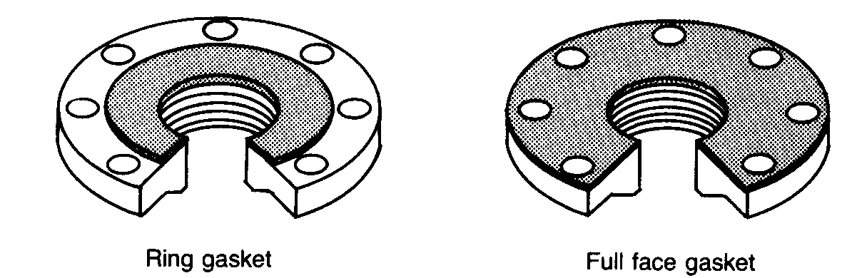
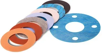
 Asbestos-Free GasketsNon-asbestos gaskets are the simplest type of gasket for flanges and are produced by cutting graphite, organic, or inorganic non-asbestos sheets into a round-gasket shape (generally, with water jet cutting machines). The two main types of non-asbestos gaskets for flanges are the “full face” (FF) for FF flanges and the “flat ring” type for raised face flanges (RF). These two key sub-types are shown in the image below:
In piping systems, non-asbestos gaskets are used in low-pressure, low-temperature, and non-critical applications, i.e. they represent an entry-level alternative.
The ASME B16.21 specification covers non-asbestos sheet gaskets for flanges and flanged joints (types, sheet materials, dimensions, dimensional tolerances, and marking requirements).
Non-asbestos gaskets are designed to replace asbestos-containing gaskets, which were widely used in the past due to their durability, heat resistance, and sealing capabilities but have since been phased out (in the 70s) due to health risks associated with asbestos exposure, including respiratory issues and serious illnesses like asbestosis and mesothelioma.
Composition and Features:
Non-asbestos gaskets are made from a combination of synthetic fibers, such as Aramid (a strong and heat-resistant synthetic fiber), fiberglass, and elastomeric materials like nitrile rubber, EPDM, or Neoprene. These components are mixed and bound together to create a sheet material that can be cut and shaped into gaskets. The specific composition of a non-asbestos gasket can vary depending on the manufacturer and the intended application, allowing for customization to meet different sealing requirements.
Advantages:
- Health and Safety: The primary advantage of non-asbestos gaskets is their safety; they do not pose the health risks associated with asbestos fibers.
- Versatility: These gaskets can be engineered for specific applications, with resistance to different chemicals, temperatures, and pressures.
- Durability: Non-asbestos gaskets are designed to be durable and withstand harsh operational conditions, similar to their asbestos counterparts.
- Environmental Compliance: Using non-asbestos materials aligns with global regulations and standards aimed at reducing health risks and environmental impact.
Applications:
Non-asbestos gaskets are used in a variety of settings, including:
- Piping Systems: For sealing flanges in water, gas, and chemical pipelines.
- Automotive Industry: In engines, transmissions, and other systems requiring durable seals.
- Industrial Machinery: For sealing joints in pumps, valves, and other equipment.
- HVAC Systems: In heating, ventilation, and air conditioning units to prevent leaks.
Selection Criteria:
When selecting a non-asbestos gasket, consider:
- Operating Temperature and Pressure: Ensure the gasket material can withstand the specific conditions of the application.
- Chemical Compatibility: The gasket material should resist the chemicals it will be exposed to, preventing degradation and failure.
- Compliance and Certifications: Choose gaskets that meet relevant industry standards and certifications for quality and performance.
Common Materials for Soft Gaskets
Non-asbestos gaskets for flanges are made from synthetic materials that provide similar or superior performance to asbestos gaskets without health risks. These materials are selected for their ability to withstand different temperatures, pressures, and chemical exposures.
The most common materials used to manufacture compressed-fiber gaskets are Aramid fibers (Kevlar), Teflon (PTFE), graphite, glass fibers, elastomers, and Neoprene mixed with a multitude of binder materials (the most common binder is NBR, i.e. Buna-N):
| Category | Materials |
|---|---|
| Aramid-based | Aramid + NBR binder, Aramid + SBR binder (premium) |
| Reinforced | Carbon graphite reinforced, Glass reinforced (steam service) |
| PTFE variants | PTFE bi-axially oriented (silica filler), PTFE (hollow glass microsphere), PTFE (pigment-free), Expanded PTFE, PTFE joint sealant |
| PTFE envelope | Slit type, Milled type, Formed type |
| Elastomers | SBR (styrene-butadiene), CR-chloroprene (Neoprene), EPDM, Fluorocarbon (Viton), BUNA-N (NBR), Hypalon |
| Graphite | Pure graphite, Graphite + SS316/316L insert |
| Specialty | MICA sheet, Ceramic fiber |
Non-Asbestos Material Properties
The main features of each material class listed above are:
| Material | Characteristics | Applications |
|---|---|---|
| Aramid Fiber | Known for strength, heat resistance, and durability. Often used as a replacement for asbestos. | Environments with high mechanical stress and where thermal stability is required. |
| PTFE | Highly resistant to chemicals with very low coefficient of friction. Stable across various temperatures. | Aggressive chemicals (strong acids/bases), food and pharmaceutical industries where cleanliness is critical. |
| Graphite | Excellent thermal stability, high compressibility, good resistance to most chemicals. | High-temperature applications: exhaust systems, steam services, and fire safety applications. |
| Fiberglass | Good thermal resistance and tensile strength. Less commonly used alone, often combined with other materials. | High-temperature applications, often in combination with PTFE or graphite. |
| Composite Materials | Combinations of synthetic fibers, fillers, and rubber binders tailored to specific requirements. | Versatile use across various conditions depending on composition. |
Elastomeric Compounds:
| Elastomer | Key Properties | Typical Applications |
|---|---|---|
| Nitrile Rubber (NBR) | Resistant to oils, fuels, and some chemicals | Oil and hydrocarbon applications |
| EPDM | Excellent resistance to weathering, ozone, UV, and many chemicals | Water and steam services |
| Neoprene | Good resistance to oils, chemicals, and flame | Refrigerants and moderate acids |
Non-asbestos gaskets can also be coated with graphite, for non-stick and steam resistance, mixed with PTFE for excellent chemical resistance, or with EPDM for potable water applications.
Dimensions
Soft Gaskets for ASME B16.5 Flanges
Non-asbestos gaskets dimensions (for ASME B16.5 FF flanges), in millimeters

| NPS | d1 (ID) | Class 150 | Class 300 | Class 400 | Class 600 | Class 900 |
|---|---|---|---|---|---|---|
| 1/2 | 21 | 48 | 54 | 54 | 54 | 64 |
| 3/4 | 27 | 57 | 67 | 67 | 67 | 70 |
| 1 | 33 | 67 | 73 | 73 | 73 | 79 |
| 1 1/4 | 42 | 76 | 83 | 83 | 83 | 89 |
| 1 1/2 | 48 | 86 | 95 | 95 | 95 | 98 |
| 2 | 60 | 105 | 111 | 111 | 111 | 143 |
| 2 1/2 | 73 | 124 | 130 | 130 | 130.2 | 165 |
| 3 | 89 | 137 | 149 | 149 | 149 | 168 |
| 3 1/2 | 102 | 162 | 165 | 162 | 162 | - |
| 4 | 114 | 175 | 181 | 178 | 194 | 206 |
| 5 | 141 | 197 | 216 | 213 | 241 | 248 |
| 6 | 168 | 222 | 251 | 248 | 267 | 289 |
| 8 | 219 | 279 | 308 | 305 | 321 | 359 |
| 10 | 273 | 340 | 362 | 359 | 400 | 435 |
| 12 | 324 | 410 | 422 | 419 | 457 | 498 |
| 14 | 356 | 451 | 486 | 483 | 492 | 521 |
| 16 | 406 | 514 | 540 | 537 | 565 | 575 |
| 18 | 457 | 549 | 597 | 594 | 613 | 638 |
| 20 | 508 | 606 | 654 | 648 | 683 | 699 |
| 24 | 610 | 718 | 775 | 768 | 791 | 838 |
All values in millimeters
Soft Gaskets for ASME B16.47 - Series A Flanges
Non-asbestos gaskets dimensions (for ASME B16.47 series A flanges), in millimeters
| NPS | d1 (ID) | Class 150 | Class 300 | Class 400 | Class 600 |
|---|---|---|---|---|---|
| 26 | 660 | 775 | 835 | 832 | 867 |
| 28 | 711 | 832 | 899 | 892 | 914 |
| 30 | 762 | 883 | 953 | 946 | 972 |
| 32 | 813 | 940 | 1006 | 1003 | 1022 |
| 34 | 864 | 991 | 1057 | 1054 | 1073 |
| 36 | 914 | 1048 | 1118 | 1118 | 1130 |
| 38 | 965 | 1111 | 1054 | 1073 | 1105 |
| 40 | 1016 | 1162 | 1114 | 1127 | 1156 |
| 42 | 1067 | 1219 | 1165 | 1178 | 1219 |
| 44 | 1118 | 1276 | 1219 | 1232 | 1270 |
| 46 | 1168 | 1327 | 1273 | 1289 | 1327 |
| 48 | 1219 | 1384 | 1324 | 1346 | 1391 |
| 50 | 1270 | 1435 | 1378 | 1403 | 1448 |
| 52 | 1321 | 1492 | 1429 | 1454 | 1499 |
| 54 | 1372 | 1549 | 1492 | 1518 | 1556 |
| 56 | 1422 | 1607 | 1543 | 1568 | 1613 |
| 58 | 1473 | 1664 | 1594 | 1619 | 1664 |
| 60 | 1524 | 1715 | 1645 | 1683 | 1721 |
All values in millimeters
Soft Gaskets for ASME B16.47 - Series B Flanges
Non-asbestos gaskets dimensions (for ASME B16.47 series B flanges), in millimeters
| NPS | d1 (ID) | Class 150 | Class 300 | Class 400 | Class 600 |
|---|---|---|---|---|---|
| 26 | 660 | 725 | 772 | 746 | 765 |
| 28 | 711 | 776 | 826 | 800 | 819 |
| 30 | 762 | 827 | 886 | 857 | 879 |
| 32 | 813 | 881 | 940 | 911 | 933 |
| 34 | 864 | 935 | 994 | 962 | 997 |
| 36 | 914 | 987 | 1048 | 1022 | 1048 |
| 38 | 965 | 1045 | 1099 | - | - |
| 40 | 1016 | 1095 | 1149 | - | - |
| 42 | 1067 | 1146 | 1200 | - | - |
| 44 | 1118 | 1197 | 1251 | - | - |
| 46 | 1168 | 1256 | 1318 | - | - |
| 48 | 1219 | 1307 | 1368 | - | - |
| 50 | 1270 | 1357 | 1419 | - | - |
| 52 | 1321 | 1408 | 1470 | - | - |
| 54 | 1372 | 1464 | 1530 | - | - |
| 56 | 1422 | 1514 | 1594 | - | - |
| 58 | 1473 | 1580 | 1656 | - | - |
| 60 | 1524 | 1630 | 1705 | - | - |
All values in millimeters. Dimensional tolerances:
- For outside diameter NPS 12 and smaller: +0 / -1.5 mm.; NPS 14 and larger: +0 / -3.0 mm.
- For inside diameter NPS 12 and smaller: ± 1.5 mm; NPS 14 and larger: ± 3.0 mm
Spiral Wound Gasket (“SWG”)
What Are Spiral-Wound Gaskets?
A Spiral wound gasket for flanges features a core metal sealing element filled with graphite, PTFE, ceramic fibers, and, or non-asbestos fibers (fillers). For this reason, spiral wound gaskets are classified as “semi-metallic” gaskets.

The metal component of the spiral wound gasket provides strength to the seal, whereas the fillers enhance the gasket’s conformability and resilience. Inner and outer rings can be added to the core sealing element to simplify installation and increase the pressure rating. Spiral wound gaskets with graphite fillers are the most commonly used type.
Spiral wound gaskets withstand higher mechanical stress than soft gaskets in high temperature and high-pressure applications. They are widely used in oil and gas, chemical processing, power generation, and other sectors requiring reliable sealing under demanding conditions. They are particularly suited for:
- Fluctuating pressures and temperatures.
- High-pressure and high-temperature environments.
- Joints requiring high purity or where aggressive chemicals are present.
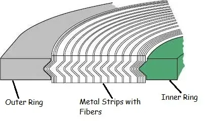
The structure of SWG gaskets consist of:
- Metallic Outer Ring: Often included as a centering ring, it provides radial strength and centers the gasket within the flange. It also is a compression stop and helps protect the gasket’s inner winding.
- Metallic Windings: Typically made from stainless steel or other alloys, these windings provide structural strength and ensure the gasket’s ability to withstand high pressures and temperatures.
- Filler Material: Sandwiched between the metal windings, common fillers include flexible graphite, PTFE (Polytetrafluoroethylene), or non-asbestos materials. The filler material is selected based on chemical compatibility with the media being sealed and the operational conditions.
- Inner Ring (optional): Used in some designs to prevent inward buckling of the gasket and protect the windings from corrosive or erosive media.
Flexitallic USA introduced spiral wound gaskets in the petrochemical industry back in 1912 to cope with an increasing demand for leak-proof seals in applications with higher and higher (and fluctuating) temperatures and pressures. Other reputable spiral wound gasket manufacturers are Garlock and Lamons. Since then, many manufacturers of SWG has emerged, also in developing countries as India and China.
The diameter of a spiral wound gasket may range between a few mm and up to 5.000 mm, and the typical thicknesses of spiral wound gaskets ranges from 3.2, 4.5, 6.4, to 7.2 mm.
A Spiral wound gasket may be ordered in different shapes, such as oblong, rectangular, oval, pear, and diamond.
ASME B16.20 is the spiral wound gasket specification.
The round type is, of course, the standard shape for the raised face (RF), male-and-female (M&F), and tongue-and-groove flanges (T&G) for petrochemical applications.
Types of SWG
A few different types of spiral wound gaskets exist, depending on two main construction parameters:
- the number of rings (center, outer and inner rings)
- the materials of the inner and the outer ring of the gasket
- the type of filler material used for the core-ring
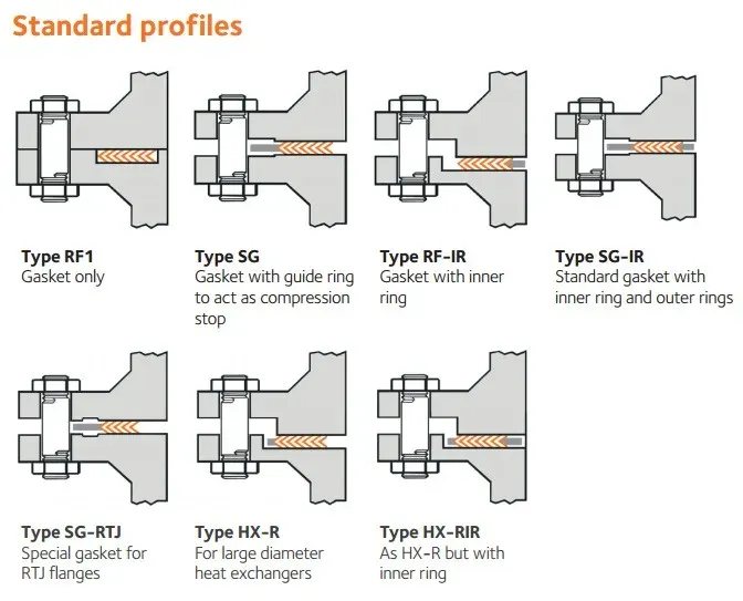
A generally accepted taxonomy for SWG comprises the following base-types:
| SWG Type | Description |
|---|---|
| Basic Type | The simplest form, consisting only of the metal spiral and filler material with no metal reinforcement on the inner and outer diameters. Suitable for tongue and groove flanges and some male-female flange arrangements. |
| With Inner Ring | Includes an inner metal ring that prevents inward buckling, is a heat and corrosion barrier, and ensures the filler material does not contact the process fluid. Used for raised face, male-female, and tongue-and-groove flanges in corrosive media applications. |
| With Outer Ring (Centering Ring) | Incorporates an outer metal ring as a centering device and compression stop, providing additional radial strength and preventing over-compression. Widely used with raised face flanges for alignment during installation. |
| With Inner and Outer Rings | Combines both rings: the inner ring protects against inward buckling and media erosion, while the outer ring centers the gasket and acts as a compression limit. Ideal for standard raised face and flat face flanges. |
| Windings With Metal Strip | Features a metal strip wound together with the filler material for enhanced strength. Less common, but used in extremely high-pressure applications requiring additional mechanical strength. |
| Specialty Gaskets | Custom-engineered for specific applications, with layers of different metals or fillers to address unique chemical resistance, temperature, or pressure requirements. Designed for particular operational conditions or regulatory compliance. |
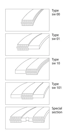
Based on this basic classification, it is therefore common to see in the catalogs of gaskets manufacturers nomenclatures like:
- Type 00: Spiral Wound Gasket without rings: they are used for tongue and groove, male and female flanges.
- Type 01: Spiral Wound Gasket with inner ring: they are used for male and female or special flange types.
- Type 10: Spiral Wound Gasket with outer ring: they are used for raised face flanges.
- Type 101: Spiral Wound Gasket with inner and outer rings: they are used for raised face flanges.
- Special Section: Spiral Wound Gasket with special rings: they are used for special flanges and special usage.
Each manufacturer, of course, uses specific codes to designate different types of spiral wound gasket in production, but the typical designs are recurring regardless of the producer.
The image shows how the different spiral wound gasket types are used for flanged joints in piping applications:
SWG Materials
Spiral Winding Materials
The sealing element of a spiral wound gasket is produced by interleaving plies of alternating metal winding strips combined with a filler material. The formed metal strip is the primary sealing element of this type of semi-metallic gasket.
The most common winding materials are:
- SS 304L
- SS 316L
- SS 321
- Titanium
- Nickel
- Nickel alloys
- Duplex
Filler Materials
Filler materials are used to enhance the conformability and resilience of a spiral wound gasket. The most used filler material is graphite, however, other filler materials may be used depending on the application:
- Graphite
- PTFE
- Ceramic fibers
- Non-asbestos
Inner and Outer Rings Materials
The inner and outer rings of a spiral wound gasket may be the same material as the winding core or a different one.
Solid inner rings are required by the ASME B16.20 specification for flanges with pressure rating 900# NPS 24 and larger, 1500# NPS 12 and larger, pressure class 2500#, NPS 4 and larger.
The inner ring improves the pressure rating of the spiral wound gasket, as it provides additional compression to the flanged joint and provides a heat and corrosion barrier protecting the gasket windings and the flanges from erosion.
Mechanical Properties by Material
| Material | DIN Specification | DIN Material Nr. | AISI/UNS | BS/ASTM | Hardness HV 10 | Min Temp (°C) | Max Temp (°C) | Density (g/cm³) |
|---|---|---|---|---|---|---|---|---|
| Soft Iron (Armco) | - | 1.1003 | - | - | 90-100 | -60 | 500 | 7.85 |
| Steel (LCS) | RSt.37.2 | 1.0038 | - | - | 100-130 | -40 | 500 | 7.85 |
| Stainless Steel 304 | X5CrNi 18 | 1.4301 | 304 | 304S15/16/31 | 130-180 | -250 | 550 | 7.9 |
| Stainless Steel 304L | X2CrNi 189 | 1.4306 | 304L | 304S11 | 130-190 | -250 | 550 | 7.9 |
| Stainless Steel 309 | X15CrNiMo 2012 | 1.4828 | 309 | 309S24 | 130-190 | -100 | 1000 | 7.9 |
| Stainless Steel 316 | X5CrNiMo 1810 | 1.4401 | 316 | 316S31/33 | 130-180 | -100 | 550 | 7.9 |
| Stainless Steel 316L | X2CrNiMo 1810 | 1.4404 | 316L | 316S11/13 | 130-190 | -100 | 550 | 7.9 |
| Stainless Steel 316Ti | X10CrNiMoTi 1810 | 1.4571 | 316Ti | 320S31 | 130-190 | -100 | 550 | 7.8 |
| Stainless Steel 321 | X10CrNiTi 189 | 1.4541 | 321 | 321S12/49/87 | 130-190 | -250 | 550 | 7.9 |
| Stainless Steel 347 | X10CrNiNb 189 | 1.4550 | 347 | 347S31 | 130-190 | -250 | 550 | 7.9 |
| Nickel 200 | Ni 99.2 | 2.4066 | N02200 | 3072-76 NA11 | 90-120 | -250 | 600 | 8.9 |
| Monel 400 | NiCu 30 Fe | 2.4360 | N04400 | 3072-76 NA13 | 110-150 | -125 | 600 | 8.8 |
| Inconel 600 | NiCr 15 Fe | 2.4816 | N06600 | 3072-76 NA14 | 120-180 | -100 | 950 | 8.4 |
| Incoloy 800 | X10NiCrAITi 3220 | 1.4876 | N08800 | 3072-76 NA15 | 140-220 | -100 | 850 | 8.4 |
| Incoloy 825 | NiCR 21 Mo | 2.4858 | N08825 | 3072-76 NA16 | 120-180 | -100 | 450 | 8.14 |
| Hastelloy B2 | NMo 28 | 2.4617 | N10665 | - | 170-230 | -200 | 450 | 9.2 |
| Hastelloy C276 | NiMo 16Cr15W | 2.4819 | N10276 | - | 170-230 | -200 | 450 | 8.9 |
| Titanium | Ti 99.8 | 3.7025 | - | - | 110-140 | -250 | 500 | 4.5 |
Color Coding for SWG
Spiral wound gaskets featuring various combinations of winding and filler materials can be readily identified through standardized color codes. Each material combination is marked with distinct colors: the primary color represents the winding material, while stripes signal the type of filler used.
- Metallic winding materials: the metallic winding material is designated by a solid color identification around the outside edge of the centering, as shown in the image below
- Non-metallic filler color coding: the gasket filler materials are designated by several stripes placed at equal distances around the edge of the centering ring
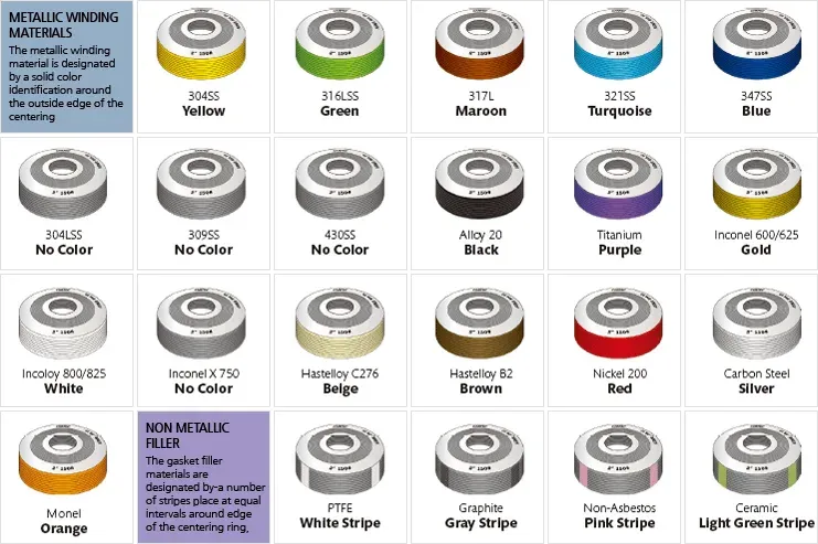
Color Codes for Winding Materials
| Metallic Winding Material for Spiral Wound Gasket | Abbreviated WindingMaterial Name | Color Code |
|---|---|---|
| Carbon steel | CRS | Silver |
| 304 SS | 304 | Yellow |
| 304 L SS | 304 L | No color |
| 309 SS | 309 | No color |
| 316 L SS | 316 L | Green |
| 347 SS | 347 | Blue |
| 321 SS | 321 | Turquoise |
| Monel 400 | MON | Orange |
| Nickel 200 | NI | Red |
| Titanium | TI | Purple |
| Hastelloy B | HAST B | Brown |
| Hastelloy C | HAST C | Beige |
Color Codes for Filler Materials
| Polytetrafluoroethylene | PTFE | White stripe |
|---|---|---|
| Mica-graphite | Manufacturer’s designation | Pink stripe |
| Flexible graphite | F.G. | Gray stripe |
| Ceramic | CER | Light green stripe |
| Inconel 600 | Inconel 600 | Gold |
|---|---|---|
| Inconel 625 | Inconel 625 | Gold |
| Incoloy 800 | Incoloy 800 H / HT | White |
| Incoloy 825 | Incoloy 825 | White |
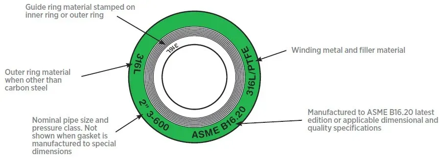
ASME Marking Requirements for SWG
ASME B16.20 defines specific marking requirements for spiral wound gaskets to ensure proper identification and application. These markings enable correct gasket selection and use in piping systems.
According to ASME B16.20, the following information must be marked directly on the spiral wound gasket or on a tag attached to the gasket:
| Required Marking | Purpose |
|---|---|
| Manufacturer’s Name or Trademark | Identifies the manufacturer, ensuring traceability and accountability. |
| Gasket Type | Indicates the specific SWG construction and design features. |
| Nominal Pipe Size and Pressure Class | Confirms the size and pressure rating of the compatible flanges, ensuring system compatibility. |
| Material Identification | Winding material (e.g., SS, Monel), filler material (e.g., flexible graphite, PTFE), and inner/outer ring material (if applicable) must all be identified. |
| ASME B16.20 Designation | Confirms the gasket has been manufactured under the ASME B16.20 standard. |
Optional or additional markings may include special features or modifications to the standard design, and heat code or lot number for traceability back to the manufacturing batch.
The illustration shows the typical marking of spiral wound gaskets:
Dimensions of SWG
Size of SWG Class 150
Dimensions of class 150 spiral wound gaskets for ASME B16.5 (in mm.)
 Spiral wound gasket dimensions
| NPS | Inner Ring | Sealing Element | Outer Ring |
|---|---|---|---|
| Inside Diameter (d1) | Inside Diameter (d2) | Outside Diameter(d3) | Outside Diameter (d4) |
| 1/2 | 14.2 | 19.1 | 31.8 |
| 3/4 | 20.6 | 25.4 | 39.6 |
| 1 | 26.9 | 31.8 | 47.8 |
| 1¼ | 38.1 | 47.8 | 60.5 |
| 1½ | 44.5 | 54.1 | 69.9 |
| 2 | 55.6 | 69.9 | 85.9 |
| 2½ | 66.5 | 82.6 | 98.6 |
| 3 | 81 | 101.6 | 120.7 |
| 4 | 106.4 | 127 | 149.4 |
| 5 | 131.8 | 155.7 | 177.8 |
| 6 | 157.2 | 182.6 | 209.6 |
| 8 | 215.9 | 233.4 | 263.7 |
| 10 | 268.2 | 287.3 | 317.5 |
| 12 | 317.5 | 339.9 | 374.7 |
| 14 | 349.3 | 371.6 | 406.4 |
| 16 | 400.1 | 422.4 | 463.6 |
| 18 | 449.3 | 474.7 | 527.1 |
| 20 | 500.1 | 525.5 | 577.9 |
| 24 | 603.3 | 628.7 | 685.8 |
| NOTES: • All dimensions are in millimeters • Spiral Wound gasket with Inner - and Outer ring • d1 = Inside diameter Inner ring. • d2 = Inside diameter sealing element when no Inner ring is used. • d3 = Outside diameter of sealing element. • d4 = Outside diameter of an Outer ring | |||
| The thickness of the inner and outer ring: 2.97 mm - 3.33 mm. • Thickness sealing element: 4.45 mm. • Tolerance Outside diameter for NPS 1/2 through NPS 8 is ± 0.8 mm; for NPS 10 through NPS 24 tolerance is + 1.5 mm - 0.8 mm. • There is no class 400 flanges NPS 1/2 thru NPS 3 (use Class 600), class 900 flanges NPS 1/2 thru NPS 2½ (use Class 1500), or class 2500 flanges NPS 14 or larger. |
Size of SWG Class 300
Dimensions of class 300 spiral wound gaskets for ASME B16.5 (in mm.)
Dimensions of spiral wound gaskets
| NPS | Inner Ring | Sealing Element | Outer Ring |
|---|---|---|---|
| Inside Diameter (d1) | Inside Diameter (d2) | Outside Diameter (d3) | Outside Diameter (d4) |
| 1/2 | 14.2 | 19.1 | 31.8 |
| 3/4 | 20.6 | 25.4 | 39.6 |
| 1 | 26.9 | 31.8 | 47.8 |
| 1¼ | 38.1 | 47.8 | 60.5 |
| 1½ | 44.5 | 54.1 | 69.9 |
| 2 | 55.6 | 69.9 | 85.9 |
| 2½ | 66.5 | 82.6 | 98.6 |
| 3 | 81 | 101.6 | 120.7 |
| 4 | 106.4 | 127 | 149.4 |
| 5 | 131.8 | 155.7 | 177.8 |
| 6 | 157.2 | 182.6 | 209.6 |
| 8 | 215.9 | 233.4 | 263.7 |
| 10 | 268.2 | 287.3 | 317.5 |
| 12 | 317.5 | 339.9 | 374.7 |
| 14 | 349.3 | 371.6 | 406.4 |
| 16 | 400.1 | 422.4 | 463.6 |
| 18 | 449.3 | 474.7 | 527.1 |
| 20 | 500.1 | 525.6 | 577.9 |
| 24 | 603.3 | 628.7 | 685.8 |
| NOTES: • All dimensions are in millimeters • Spiral Wound gasket with Inner - and Outer ring • d1 = Inside diameter Inner ring. • d2 = Inside diameter sealing element when no Inner ring is used. • d3 = Outside diameter of sealing element. • d4 = Outside diameter of an Outer ring | |||
| The thickness of the inner and outer ring: 2.97 mm - 3.33 mm. • Thickness sealing element: 4.45 mm. • Tolerance Outside diameter for NPS 1/2 through NPS 8 is ± 0.8 mm; for NPS 10 through NPS 24 tolerance is + 1.5 mm - 0.8 mm. • There is no class 400 flanges NPS 1/2 thru NPS 3 (use Class 600), class 900 flanges NPS 1/2 thru NPS 2½ (use Class 1500), or class 2500 flanges NPS 14 or larger. |
Size of SWG Class 400
Dimensions of class 400 spiral wound gaskets for ASME B16.5 (in mm.)
Dimensions of spiral wound gasket
| NPS | Inner Ring | Sealing Element | Outer Ring |
|---|---|---|---|
| Inside Diameter (d1) | Inside Diameter (d2) | Outside Diameter (d3) | Outside Diameter (d4) |
| 1/2 | 14.2 | 19.1 | 31.8 |
| 3/4 | 20.6 | 25.4 | 39.6 |
| 1 | 26.9 | 31.8 | 47.8 |
| 1¼ | 38.1 | 47.8 | 60.5 |
| 1½ | 44.5 | 54.1 | 69.9 |
| 2 | 55.6 | 69.9 | 85.9 |
| 2½ | 66.5 | 82.6 | 98.6 |
| 3 | 81 | 101.6 | 120.7 |
| 4 | 102.6 | 120.7 | 149.4 |
| 5 | 128.3 | 147.6 | 177.8 |
| 6 | 154.9 | 174.8 | 209.6 |
| 8 | 205.7 | 225.6 | 263.7 |
| 10 | 255.3 | 274.6 | 317.5 |
| 12 | 307.3 | 327.2 | 374.7 |
| 14 | 342.9 | 362 | 406.4 |
| 16 | 389.9 | 412.8 | 463.6 |
| 18 | 438.2 | 469.9 | 527.1 |
| 20 | 489 | 520.7 | 577.9 |
| 24 | 590.6 | 628.7 | 685.8 |
| NOTES: • All dimensions are in millimeters • Spiral Wound gasket with Inner - and Outer ring • d1 = Inside diameter Inner ring. • d2 = Inside diameter sealing element when no Inner ring is used. • d3 = Outside diameter of sealing element. • d4 = Outside diameter of an Outer ring | |||
| _The thickness of the inner and outer ring: 2.97 mm - 3.33 mm. • Thickness sealing element: 4.45 mm. • Tolerance Outside diameter for NPS 1/2 through NPS 8 is ± 0.8 mm; for NPS 10 through NPS 24 tolerance is + 1.5 mm - 0.8 mm. • There is no class 400 flanges NPS 1/2 thru NPS 3 (use Class 600), class 900 flanges NPS 1/2 thru NPS 2½ (use Class 1500), or class 2500 flanges NPS 14 or larger. _ |
Size of SWG Class 600
Dimensions of class 600 spiral wound gaskets for ASME B16.5 (in mm.)
Dimensions of spiral wound gaskets
| NPS | Inner Ring | Sealing Element | Outer Ring | | -------------------- | -------------------- | --------------------- | --------------------- | ----- | | Inside Diameter (d1) | Inside Diameter (d2) | Outside Diameter (d3) | Outside Diameter (d4) | | 1/2 | 14.2 | 19.1 | 31.8 | 54.1 | | 3/4 | 20.6 | 25.4 | 39.6 | 66.8 | | 1 | 26.9 | 31.8 | 47.8 | 73.2 | | 1¼ | 38.1 | 47.8 | 60.5 | 82.6 | | 1½ | 44.5 | 54.1 | 69.9 | 95.3 | | 2 | 55.6 | 69.9 | 85.9 | 111.3 | | 2½ | 66.5 | 82.6 | 98.6 | 130.3 | | 3 | 78.7 | 101.6 | 120.7 | 149.4 | | 4 | 102.6 | 120.7 | 149.4 | 193.8 | | 5 | 128.3 | 147.6 | 177.8 | 241.3 | | 6 | 154.9 | 174.8 | 209.6 | 266.7 | | 8 | 205.7 | 225.6 | 263.7 | 320.8 | | 10 | 255.3 | 274.6 | 317.5 | 400.1 | | 12 | 307.3 | 327.2 | 374.7 | 457.2 | | 14 | 342.9 | 362 | 406.4 | 492.3 | | 16 | 389.9 | 412.8 | 463.6 | 565.2 | | 18 | 438.2 | 469.9 | 527.1 | 612.9 | | 20 | 489 | 520.7 | 577.9 | 682.8 | | 24 | 590.6 | 628.7 | 685.8 | 790.7 |
NOTES: • All dimensions are in millimeters • Spiral Wound gasket with Inner - and Outer ring • d1 = Inside diameter Inner ring. • d2 = Inside diameter sealing element when no Inner ring is used. • d3 = Outside diameter of sealing element. • d4 = Outside diameter of an Outer ring The thickness of the inner and outer ring: 2.97 mm - 3.33 mm. • Thickness sealing element: 4.45 mm. • Tolerance Outside diameter for NPS 1/2 through NPS 8 is ± 0.8 mm; for NPS 10 through NPS 24 tolerance is + 1.5 mm - 0.8 mm. • There is no class 400 flanges NPS 1/2 thru NPS 3 (use Class 600), class 900 flanges NPS 1/2 thru NPS 2½ (use Class 1500), or class 2500 flanges NPS 14 or larger.
Size of SWG Class 900
Dimensions of class 900 spiral wound gaskets for ASME B16.5 (in mm.)
Dimensions of spiral wound gaskets
| NPS | Inner Ring | Sealing Element | Outer Ring |
|---|---|---|---|
| Inside Diameter (d1) | Inside Diameter (d2) | Outside Diameter(d3) | Outside Diameter (d4) |
| 1/2 | 14.2 | 19.1 | 31.8 |
| 3/4 | 20.6 | 25.4 | 39.6 |
| 1 | 26.9 | 31.8 | 47.8 |
| 1¼ | 33.3 | 39.6 | 60.5 |
| 1½ | 41.4 | 47.8 | 69.9 |
| 2 | 52.3 | 58.7 | 85.9 |
| 2½ | 63.5 | 69.9 | 98.6 |
| 3 | 78.7 | 95.3 | 120.7 |
| 4 | 102.6 | 120.7 | 149.4 |
| 5 | 128.3 | 147.6 | 177.8 |
| 6 | 154.9 | 174.8 | 209.6 |
| 8 | 196.9 | 222.3 | 257.3 |
| 10 | 246.1 | 276.4 | 311.2 |
| 12 | 292.1 | 323.9 | 368.3 |
| 14 | 320.8 | 355.6 | 400.1 |
| 16 | 374.7 | 412.8 | 457.2 |
| 18 | 425.5 | 463.6 | 520.7 |
| 20 | 482.6 | 520.7 | 571.5 |
| 24 | 590.6 | 628.7 | 679.5 |
| NOTES: • All dimensions are in millimeters • Spiral Wound gasket with Inner - and Outer ring • d1 = Inside diameter Inner ring. • d2 = Inside diameter sealing element when no Inner ring is used. • d3 = Outside diameter of sealing element. • d4 = Outside diameter of an Outer ring | |||
| The thickness of the inner and outer ring: 2.97 mm - 3.33 mm. • Thickness sealing element: 4.45 mm. • Tolerance Outside diameter for NPS 1/2 through NPS 8 is ± 0.8 mm; for NPS 10 through NPS 24 tolerance is + 1.5 mm - 0.8 mm. • There is no class 400 flanges NPS 1/2 thru NPS 3 (use Class 600), class 900 flanges NPS 1/2 thru NPS 2½ (use Class 1500), or class 2500 flanges NPS 14 or larger. |
Size of SWG Class 1500
Dimensions of class 1500 spiral wound gaskets for ASME B16.5 (in mm.)
Dimensions of spiral wound gaskets
| NPS | Inner Ring | Sealing Element | Outer Ring | | -------------------- | -------------------- | -------------------- | --------------------- | ----- | | Inside Diameter (d1) | Inside Diameter (d2) | Outside Diameter(d3) | Outside Diameter (d4) | | 1/2 | 14.2 | 19.1 | 31.8 | 63.5 | | 3/4 | 20.6 | 25.4 | 39.6 | 69.9 | | 1 | 26.9 | 31.8 | 47.8 | 79.5 | | 1¼ | 33.3 | 39.6 | 60.5 | 88.9 | | 1½ | 41.4 | 47.8 | 69.9 | 98.6 | | 2 | 52.3 | 58.7 | 85.9 | 143 | | 2½ | 63.5 | 69.9 | 98.6 | 165.1 | | 3 | 78.7 | 92.2 | 120.7 | 174.8 | | 4 | 97.8 | 117.6 | 149.4 | 209.6 | | 5 | 124.5 | 143 | 177.8 | 254 | | 6 | 147.3 | 171.5 | 209.6 | 282.7 | | 8 | 196.9 | 215.9 | 257.3 | 352.6 | | 10 | 246.1 | 266.7 | 311.2 | 435.1 | | 12 | 292.1 | 323.9 | 368.3 | 520.7 | | 14 | 320.8 | 362 | 400.1 | 577.9 | | 16 | 374.7 | 406.4 | 457.2 | 641.4 | | 18 | 425.5 | 463.6 | 520.7 | 704.9 | | 20 | 476.3 | 514.4 | 571.5 | 755.7 | | 24 | 577.9 | 616 | 679.5 | 901.7 |
NOTES: • All dimensions are in millimeters • Spiral Wound gasket with Inner - and Outer ring • d1 = Inside diameter Inner ring. • d2 = Inside diameter sealing element when no Inner ring is used. • d3 = Outside diameter of sealing element. • d4 = Outside diameter of an Outer ring
The thickness of the inner and outer ring: 2.97 mm - 3.33 mm. • Thickness sealing element: 4.45 mm. • Tolerance Outside diameter for NPS 1/2 through NPS 8 is ± 0.8 mm; for NPS 10 through NPS 24 tolerance is + 1.5 mm - 0.8 mm. • There is no class 400 flanges NPS 1/2 thru NPS 3 (use Class 600), class 900 flanges NPS 1/2 thru NPS 2½ (use Class 1500), or class 2500 flanges NPS 14 or larger.
Size of SWG Class 2500
Dimensions of class 2500 spiral wound gaskets for ASME B16.5 (in mm.)
Dimensions of spiral wound gaskets
| NPS | Inner Ring | Sealing Element | Outer Ring | | -------------------- | -------------------- | -------------------- | --------------------- | ----- | | Inside Diameter (d1) | Inside Diameter (d2) | Outside Diameter(d3) | Outside Diameter (d4) | | 1/2 | 14.2 | 19.1 | 31.8 | 69.9 | | 3/4 | 20.6 | 25.4 | 39.6 | 76.2 | | 1 | 26.9 | 31.8 | 47.8 | 85.9 | | 1¼ | 33.3 | 39.6 | 60.5 | 104.9 | | 1½ | 41.4 | 47.8 | 69.9 | 117.6 | | 2 | 52.3 | 58.7 | 85.9 | 146 | | 2½ | 63.5 | 69.9 | 98.6 | 168.4 | | 3 | 78.7 | 92.2 | 120.7 | 196.9 | | 4 | 97.8 | 117.6 | 149.4 | 235 | | 5 | 124.5 | 143 | 177.8 | 279.4 | | 6 | 147.3 | 171.5 | 209.6 | 317.5 | | 8 | 196.9 | 215.9 | 257.3 | 387.4 | | 10 | 246.1 | 270 | 311.2 | 476.3 | | 12 | 292.1 | 317.5 | 368.3 | 549.4 |
NOTES: • All dimensions are in millimeters • Spiral Wound gasket with Inner - and Outer ring • d1 = Inside diameter Inner ring. • d2 = Inside diameter sealing element when no Inner ring is used. • d3 = Outside diameter of sealing element. • d4 = Outside diameter of an Outer ring The thickness of the inner and outer ring: 2.97 mm - 3.33 mm. • Thickness sealing element: 4.45 mm. • Tolerance Outside diameter for NPS 1/2 through NPS 8 is ± 0.8 mm; for NPS 10 through NPS 24 tolerance is + 1.5 mm - 0.8 mm. • There is no class 400 flanges NPS 1/2 thru NPS 3 (use Class 600), class 900 flanges NPS 1/2 thru NPS 2½ (use Class 1500), or class 2500 flanges NPS 14 or larger.
Ring Joint Gaskets Style R, RX, BX (“RTJ”)
What Is a Ring Joint Gasket?
A ring joint gasket (RTJ) is a metal gasket designed for high-pressure and high-temperature applications in the oil, gas, petrochemical, and offshore industries. RTJ gaskets seal flanged connections subjected to extreme conditions where conventional gaskets would fail. They are used with ring-type joint (RTJ) flanges, which have grooves cut into their faces to accommodate the gasket.
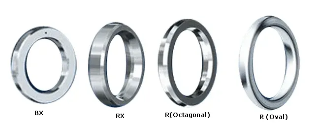
Ring joint gaskets come in oval and octagonal cross-sections (the most common shapes), plus BX and RX styles designed for specific RTJ flanges and pressures. They are made from soft iron, stainless steel, Hastelloy, Inconel, and Monel, selected based on temperature, pressure, and chemical compatibility.
A Ring Joint Gasket provides a strong metal-to-metal seal between two mating RTJ flanges. As the flanges are bolted, the softer material of the ring joint gasket is “squeezed” into the flange grooves (made of a harder material) and seals the connection tightly. RTJ gaskets are available in three styles: R (oval, octagonal), RX, and BX.
RTJ gaskets provide a durable seal for flanges, valves, piping spools, and vessels at high pressures and temperatures typical of petrochemical processes. They offer a high-integrity metal-to-metal seal that withstands significant pressure variations and vibrations, excellent temperature and pressure resistance, and potential reusability provided the gasket is undamaged and correctly reinstalled.
RTJ gaskets are available in different designs (called “styles”) and dimensions, as illustrated in the picture below (BX, R, and BX).
RTJ Gaskets Types
R Type Ring Joint Gasket (Oval and Octagonal)
“Style R” is the most common RTJ gasket type. R-type ring joint gaskets are available in oval or octagonal cross-sections and manufactured according to API 6A and ASME B16.20 to suit API 6B and ASME/ANSI B16.5 flanges.
This type of RTJ gasket is machined to tight manufacturing tolerances to ensure correct installation with standard ASME B16.5 and API 6B ring joint faced flanges. “R style” oval and octagonal RTJ gaskets can seal pressures up to 6.250 psi by ASME B16.20 and up to 5.000 psi according to the API 6A pressure ratings.
Type R RTJ gaskets are frequently used for valve covers.
Style RX RTJ Gasket
The RX-type RTJ gasket is manufactured according to API 6A and ASME B16.20 to suit API 6B and ASME/ANSI B16.5 flanges.
The RX is a pressure-energized version of the R octagonal gasket and fits the R-type flat-bottomed groove.
The RX has an increased height and utilizes the internal system pressure to energize and improve the seal as internal pressure increases.
Some RX sizes have a pressure relief hole to equalize pressure on both sides of the sealing faces.
Style BX RTJ Gasket
The BX-type RTJ gaskets are manufactured according to API 6A and are suitable for use in high-pressure API 6BX flanges.
The gaskets form a metal-to-metal seal on assembly and the efficiency improves as internal pressure increases.
All BX sizes have a pressure relief hole to equalize pressure across sealing faces.
RTJ Gasket Materials
The material of RTJ gaskets shall match the material of the flange but must have a lower hardness: this is to ensure that the gasket, and not the flange, gets plastically deformed within the groove of the flange as the two mating flanges are bolted together.
In case a harder material for the ring-type joint is used, the groove of the flange would be damaged as the flanges are tightened (the hardness values for ring joint gaskets are given below).
Types of Materials for Ring Joint Gaskets
| RTJ GASKET MATERIAL | RING ID | ASTM GRADE | DIN GRADE | WKSTOFF NUMBER | AISIGRADE | BSGRADE | OTHER SPECS |
|---|---|---|---|---|---|---|---|
| Soft Iron | D | 1.1003 / 1.0335 | Aramco / StW24 | ||||
| LCS | S | 1.1003 / 1.0335 | Aramco / StW24 | ||||
| CS360 LT | CS360LT | A516 Gr70 | |||||
| 4140 | 4140 | UNS G41400 | 42CrMo4 | 1.7225 | 4140 | ||
| F5 | F5 | UNS K42544 | 12CrMo195 | 1.7362 | 5Cr 1/2Mo | ||
| SS304 | S304 | S30400 | X5CrNi 18 9 | 1.4301 | 304 | 304S15 | |
| SS304L | S304L | S30403 | X2CrNi 18 9 | 1.4306 | 304L | 304SS12 | |
| SS309 | S309 | S30900 | X15CrNiSi2012 | 1.4828 | 309 | 309S24 | |
| SS310 | S310 | S31008 | XX15CrNiSi2520 | 1.4841 | 310 | 310S24 | |
| SS316 | S316 | S31600 | X5CrNiMo18 10 | 1.4401 | 316 | 316S16 | |
| SS316L | S316L | S31603 | X2CrNiMo18 10 | 1.4404 | 316L | 316S11/316S12 | |
| SS316L UREA | S316UG | S31603 | X2CrNiMo 18 14 3 | 1.4435 | |||
| SS316Ti | S316Ti | S31635 | X10CrNiMoTi1810 | 1.4571 | 316Ti | 320S31/320S17 | |
| SS321 | S321 | S32100 | X10CrNiTi18 9 | 1.4541 | 321 | 321S12 | |
| SS347 | S347 | S34700 | X10CrNiNb 18 9 | 1.455 | 347 | 347S51 | |
| SS410 | S410 | S41000 | X10Cr13 | 1.4006 | 410 | 410S21 | |
| Monel 400 | Monel400 | N04400 | NiCu30Fe | 2.436 | |||
| Inconel 600 | INC600 | N06600 | NiCr15Fe | 2.4816 | |||
| Inconel 625 | INC625 | N06625 | NiCr22Mo9Nb | 2.4856 | |||
| Inconel 718 | INC718 | N07718 | |||||
| Incoloy 800 | INC800 | N08800 | X5NiCrAlTi31-20 | 1.4958 | |||
| Incoloy 800H | INC800H | N08810 | 1.4958 | ||||
| Incoloy 825 | INC825 | N08825 | NiCr21Mo | 2.4858 | |||
| 904L | 904L | N08904 | X1NiCrMoCu25-20-5 | 1.4539 | |||
| F51 | F51 | S31803 | X2CrNiMoN22-5-3 | 1.4462 | 2205 /Duplex | ||
| F53 | F53 | S32750 | X2CrNiMoN25-7-4 | 1.441 | |||
| F55 | F55 | S32760 | X2CrNiMoCuWN 25 7 4 | 1.4501 | Zeron 100 | ||
| F60 | F60 | S32205 | Duplex | ||||
| Titanium | Ti | R 50400 | 3.7035 | ||||
| 17-4PH | 17-4PH | S17400 | 1.4542 | 630 | |||
| S254 | S254 | S31254 | X1CrNiMoCuN20-18-7 | 1.4547 | F44 / 6Mo | ||
| C276 | C276 | N10276 | NiMo16Cr15W | 2.4819 | Hastelloy | ||
| Alloy 28 | Alloy28 | N08028 | X1 NiCrMoCuN 31 27 4 | 1.4563 | SANICRO 28 |
Mechanical Properties Ring Joint Gaskets Materials
| | Maximum Hardness of RTJ Gaskets | | | ---------------------- | ------------------------------- | --- | ---- | | RTJ Gasket Material | Brinell | HRB | ID | | Soft Iron-S | 90 | 56 | D | | Low Carbon Steel | 120 | 68 | S | | 4 - 6% Chrome1/2% Moly | 130 | 72 | F5 | | SS 304 Stainless Steel | 160 | 83 | S304 | | SS 316 Stainless Steel | 160 | 83 | S316 | | SS 347 Stainless Steel | 160 | 83 | S347 | | SS 410 Stainless Steel | 170 | 96 | S410 |
RTJ Gasket Dimensions (ASME B16.20)
Style R Ring Joint Gaskets Dimensions (for ASME B16.5 flanges)

| RTJ GASKET RING NUMBER | Diameter P | Width A | Height | Oct C | Oct R1 | NPS / CLASS | | ---------------------- | ---------- | ------- | ------ | ----- | ------ | ----------- | ------------------- | | Oval B | Oct H | | R 11 | 34.14 | 6.35 | 11.2 | 9.7 | 4.32 | 1.5 | 1/2300 / 600 | | R 12 | 39.7 | 7.95 | 14.2 | 12.7 | 5.23 | 1.5 | 1/2900 / 1500 | | R 13 | 42.88 | 7.95 | 14.2 | 12.7 | 5.23 | 1.5 | 3/4300 / 6001/22500 | | R 14 | 44.45 | 7.95 | 14.2 | 12.7 | 5.23 | 1.5 | 3/4900 / 1500 | | R 15 | 47.63 | 7.95 | 14.2 | 12.7 | 5.23 | 1.5 | 1150 | | R 16 | 50.8 | 7.95 | 14.2 | 12.7 | 5.23 | 1.5 | 1300 / 15003/42500 | | R 17 | 57.15 | 7.95 | 14.2 | 12.7 | 5.23 | 1.5 | 1¼150 | | R 18 | 60.33 | 7.95 | 14.2 | 12.7 | 5.23 | 1.5 | 1¼300 / 150012500 | | R 19 | 65.1 | 7.95 | 14.2 | 12.7 | 5.23 | 1.5 | 1½150 | | R 20 | 68.28 | 7.95 | 14.2 | 12.7 | 5.23 | 1.5 | 1½300 / 1500 | | R 21 | 72.24 | 11.13 | 17.5 | 16 | 7.75 | 1.5 | 1¼2500 | | R 22 | 82.55 | 7.95 | 14.2 | 12.7 | 5.23 | 1.5 | 2150 | | R 23 | 82.55 | 11.13 | 17.5 | 16 | 7.75 | 1.5 | 2300 6001½2500 | | R 24 | 95.25 | 11.13 | 17.5 | 16 | 7.75 | 1.5 | 2900 / 1500 | | R 25 | 101.6 | 7.95 | 14.2 | 12.7 | 5.23 | 1.5 | 2½150 | | R 26 | 101.6 | 11.13 | 17.5 | 16 | 7.75 | 1.5 | 2½300/ 60022500 | | R 27 | 107.95 | 11.13 | 17.5 | 16 | 7.75 | 1.5 | 2½900 / 1500 | | R 28 | 111.13 | 12.7 | 19.1 | 17.5 | 8.66 | 1.5 | 2½2500 | | R 29 | 114.3 | 7.95 | 14.2 | 12.7 | 5.23 | 1.5 | 3150 | | R 30* | 117.48 | 11.13 | 17.5 | 16 | 7.75 | 1.5 | 3300 / 600 | | R 31 | 123.83 | 11.13 | 17.5 | 16 | 7.75 | 1.5 | 3300 / 900 | | R 32 | 127 | 12.7 | 19.1 | 17.5 | 8.66 | 1.5 | 32500 | | R 33 | 131.78 | 7.95 | 14.2 | 12.7 | 5.23 | 1.5 | 3½150 | | R 34 | 131.78 | 11.13 | 17.5 | 16 | 7.75 | 1.5 | 3½300 / 600 | | R 35 | 136.53 | 11.13 | 17.5 | 16 | 7.75 | 1.5 | 31500 | | R 36 | 149.23 | 7.95 | 14.2 | 12.7 | 5.23 | 1.5 | 4150 | | R 37 | 149.23 | 11.13 | 17.5 | 16 | 7.75 | 1.5 | 4300 / 900 | | R 38 | 157.18 | 15.88 | 22.4 | 20.6 | 10.49 | 1.5 | 42500 | | R 39 | 161.93 | 11.13 | 17.5 | 16 | 7.75 | 1.5 | 41500 | | R 40 | 171.45 | 7.95 | 14.2 | 12.7 | 5.23 | 1.5 | 5150 | | R 41 | 180.98 | 11.13 | 17.5 | 16 | 7.75 | 1.5 | 5300 / 900 | | R 42 | 190.5 | 19.05 | 25.4 | 23.9 | 12.32 | 1.5 | 52500 | | R 43 | 193.68 | 7.95 | 14.2 | 12.7 | 5.23 | 1.5 | 6150 | | R 44 | 193.68 | 11.13 | 17.5 | 16 | 7.75 | 1.5 | 51500 | | R 45 | 211.15 | 11.13 | 17.5 | 16 | 7.75 | 1.5 | 6300 / 900 | | R 46 | 211.15 | 12.7 | 19.1 | 17.5 | 8.66 | 1.5 | 61500 | | R 47 | 228.6 | 19.05 | 25.4 | 23.9 | 12.32 | 1.5 | 62500 | | R 48 | 247.65 | 7.95 | 14.2 | 12.7 | 5.23 | 1.5 | 8150 | | R 49 | 269.88 | 11.13 | 17.5 | 16 | 7.75 | 1.5 | 8300 / 900 | | R 50 | 269.88 | 15.88 | 22.4 | 20.6 | 10.49 | 1.5 | 81500 | | R 51 | 279.4 | 22.23 | 28.7 | 26.9 | 14.81 | 1.5 | 82500 | | R 52 | 304.8 | 7.95 | 14.2 | 12.7 | 5.23 | 1.5 | 10150 | | R 53 | 323.85 | 11.13 | 17.5 | 16 | 7.75 | 1.5 | 10300 900 | | R 54 | 323.85 | 15.88 | 22.4 | 20.6 | 10.49 | 1.5 | 101500 | | R 55 | 342.9 | 28.58 | 36.6 | 35.1 | 19.81 | 2.3 | 102500 | | R 56 | 381 | 7.95 | 14.2 | 12.7 | 5.23 | 1.5 | 12150 | | R 57 | 381 | 11.13 | 17.5 | 16 | 7.75 | 1.5 | 12300 900 | | R 58 | 381 | 22.23 | 28.7 | 26.9 | 14.81 | 1.5 | 121500 | | R 59 | 396.88 | 7.95 | 14.2 | 12.7 | 5.23 | 1.5 | 14150 | | R 60 | 406.4 | 31.75 | 39.6 | 38.1 | 22.33 | 2.3 | 122500 | | R 61 | 419.1 | 11.13 | 17.5 | 16 | 7.75 | 1.5 | 14300 600 | | R 62 | 419.1 | 15.88 | 22.4 | 20.6 | 10.49 | 1.5 | 14900 | | R 63 | 419.1 | 25.4 | 33.3 | 31.8 | 17.3 | 2.3 | 141500 | | R 64 | 454.03 | 7.95 | 14.2 | 12.7 | 5.23 | 1.5 | 16150 | | R 65 | 469.9 | 11.13 | 17.5 | 16 | 7.75 | 1.5 | 16300 600 | | R 66 | 469.9 | 15.88 | 22.4 | 20.6 | 10.49 | 1.5 | 16900 | | R 67 | 469.9 | 28.58 | 36.6 | 35.1 | 19.81 | 2.3 | 161500 | | R 68 | 517.53 | 7.95 | 14.2 | 12.7 | 5.23 | 1.5 | 18150 | | R 69 | 533.4 | 11.13 | 17.5 | 16 | 7.75 | 1.5 | 18300 600 | | R 70 | 533.4 | 19.05 | 25.4 | 23.9 | 12.32 | 1.5 | 18900 | | R 71 | 533.4 | 28.58 | 36.6 | 35.1 | 19.81 | 2.3 | 181500 | | R 72 | 558.8 | 7.95 | 14.2 | 12.7 | 5.23 | 1.5 | 20150 | | R 73 | 584.2 | 12.7 | 19.1 | 17.5 | 8.66 | 1.5 | 20300 600 | | R 74 | 584.2 | 19.05 | 25.4 | 23.9 | 12.32 | 1.5 | 20900 | | R 75 | 584.2 | 31.75 | 39.6 | 38.1 | 22.33 | 2.3 | 201500 | | R 76 | 673.1 | 7.95 | 14.2 | 12.7 | 5.23 | 1.5 | 24150 | | R 77 | 692.15 | 15.88 | 22.4 | 20.6 | 10.49 | 1.5 | 24300 600 | | R 78 | 692.15 | 25.4 | 33.3 | 31.8 | 17.3 | 2.3 | 24900 | | R 79 | 692.15 | 34.93 | 44.5 | 41.4 | 24.82 | 2.3 | 241500 |
Style R Ring Joint Gaskets Dimensions (for ASME B16.47 Series A flanges)
| RTJ GASKET RING NUMBER | DiaP | WidthA | Height | OctC | OctR1 | NPSCLASS | | ---------------------- | ------- | ------ | ------ | ---- | ----- | -------- | --------- | | OvalB | OctH | | R 93 | 749.3 | 19.05 | … | 23.9 | 12.32 | 1.5 | 26300 600 | | R 94 | 800.1 | 19.05 | … | 23.9 | 12.32 | 1.5 | 28300 600 | | R 95 | 857.25 | 19.05 | … | 23.9 | 12.32 | 1.5 | 30300 600 | | R 96 | 914.4 | 22.23 | … | 26.9 | 14.81 | 1.5 | 32300 600 | | R 97 | 965.2 | 22.23 | … | 26.9 | 14.81 | 1.5 | 34300 600 | | R 98 | 1022.35 | 22.23 | … | 26.9 | 14.81 | 1.5 | 36300 600 | | R 100 | 749.3 | 28.58 | … | 35.1 | 19.81 | 2.3 | 26900 | | R 101 | 800.1 | 31.75 | … | 38.1 | 22.33 | 2.3 | 28900 | | R 102 | 857.25 | 31.75 | … | 38.1 | 22.33 | 2.3 | 30900 | | R 103 | 914.4 | 31.75 | … | 38.1 | 22.33 | 2.3 | 32900 | | R 104 | 965.2 | 34.93 | … | 41.4 | 24.82 | 2.3 | 34900 | | R 105 | 1022.35 | 34.93 | … | 41.4 | 24.82 | 2.3 | 36900 |
Style RX Ring Joint Gaskets Dimensions
| RTJ GASKET RING NUMBER | 720-960 | 2900# | 3000# | 5000# | OD | HEIGHT | WIDTH | GASKET Wt. ( kg ) |
|---|---|---|---|---|---|---|---|---|
| RX20 | 1 ½ | - | 1 ½ | 1 ½ | 76.2 | 19.05 | 8.74 | 0.24 |
| RX23 | 2, 2 1/16 | - | 93.27 | 25.4 | 11.91 | 0.52 | ||
| RX24 | - | - | 2, 2 1/16 | 2, 2 1/16 | 105.97 | 25.4 | 11.91 | 0.6 |
| RX25 | - | - | - | 3 1/8 | 109.55 | 19.05 | 8.74 | 0.5 |
| RX26 | 2 ½ , 2 9/16 | - | - | - | 111.91 | 25.4 | 11.91 | 0.64 |
| RX27 | - | - | 2 ½, 2 9/16 | 2 ½, 2 9/16 | 118.26 | 25.4 | 11.91 | 0.68 |
| RX31 | 3 , 3 1/8 | - | 3, 3 1/8 | 134.54 | 25.4 | 11.91 | 0.78 | |
| RX35 | - | - | - | 3, 3 1/8 | 147.24 | 25.4 | 11.91 | 0.86 |
| RX37 | 4 , 4 1/16 | - | 4, 4 1/16 | - | 159.94 | 25.4 | 11.91 | 0.95 |
| RX39 | - | - | - | 4, 4 1/16 | 172.64 | 25.4 | 11.91 | 1.03 |
| RX41 | 5, 5 1/8 | - | 5, 5 1/8 | - | 191.69 | 25.4 | 11.91 | 1.15 |
| RX44 | - | - | - | 5, 5 1/8 | 204.39 | 25.4 | 11.91 | 1.23 |
| RX45 | 6, 7 1/16 | - | 6, 7 1/16 | - | 221.84 | 25.4 | 11.91 | 1.34 |
| RX46 | - | - | - | 6, 7 1/16 | 222.25 | 28.58 | 13.49 | 1.66 |
| RX47 | - | - | - | 8 | 245.26 | 41.28 | 19.84 | 3.88 |
| RX49 | 8, 9 | - | 8, 9 | 280.59 | 25.4 | 11.91 | 1.72 | |
| RX50 | - | - | - | 8, 9 | 283.36 | 31.75 | 16.66 | 2.43 |
| RX53 | 10, 11 | - | 10, 11 | 334.57 | 25.4 | 11.91 | 2.06 | |
| RX54 | - | - | - | 10, 11 | 337.34 | 31.75 | 16.66 | 2.92 |
| RX57 | 12, 13 5/8 | - | 12, 13 5/8 | 391.72 | 25.4 | 11.91 | 2.42 | |
| RX63 | - | - | 14 | 441.73 | 50.8 | 27 | 11.96 | |
| RX65 | 16, 16 3/4 | - | - | - | 480.62 | 25.4 | 11.91 | 3 |
| RX66 | - | - | 16, 16 3/4 | - | 457.99 | 31.75 | 16.66 | 4.25 |
| RX69 | 18 | - | 544.12 | 25.4 | 11.91 | 3.41 | ||
| RX70 | - | - | 18 | - | 550.06 | 41.28 | 19.84 | 9.12 |
| RX73 | 20, 21 1/4 | - | - | - | 596.11 | 31.75 | 13.49 | 5.27 |
| RX74 | - | - | 20, 20 3/4 | - | 600.86 | 41.28 | 19.84 | 10.01 |
| RX82 | - | 1 | - | - | 67.87 | 25.4 | 11.91 | 0.36 |
| RX84 | - | 1 ½ | - | - | 74.22 | 25.4 | 11.91 | 0.4 |
| RX85 | - | 2 | - | - | 90.09 | 25.4 | 13.49 | 0.4 |
| RX86 | - | 2 ½ | - | - | 103.58 | 28.58 | 15.09 | 0.81 |
| RX87 | - | 3 | - | - | 113.11 | 28.58 | 15.09 | 0.9 |
| RX88 | - | 4 | - | - | 139.29 | 31.75 | 17.48 | 1.46 |
| RX89 | - | 3 ½ | - | - | 129.77 | 31.75 | 18.26 | 3.09 |
| RX90 | - | 5 | - | - | 174.63 | 44.45 | 19.84 | 7.75 |
| RX91 | - | 10 | - | - | 286.94 | 45.24 | 30.18 | 1.5 |
| RX99 | 8 | - | 8 | - | 245.67 | 25.4 | 11.91 | 2.2 |
| RX201 | - | - | - | 1 3/8 | 51.46 | 11.3 | 5.74 | 0.1 |
| RX205 | - | - | - | 1 13/16 | 62.31 | 11.1 | 5.56 | 0.13 |
| RX210 | - | - | - | 2 9/16 | 97.64 | 19.05 | 9.53 | 0.35 |
| RX215 | - | - | - | 4 1/16 | 140.89 | 25.4 | 11.91 | 0.8 |
Style BX Ring Joint Gaskets Dimensions
| RTJ GASKET RING NUMBER | 2000# | 3000# | 5000# | 10000# | 15000# | 20000# | OUTSIDE DIA | HEIGHT OF THE RING | WIDTH OF THE RING | RTJ GASKET WEIGHT KG |
|---|---|---|---|---|---|---|---|---|---|---|
| BX 150 | - | - | - | 1 11/16 | 1 11/16 | - | 72.19 | 9.3 | 9.3 | 0.13 |
| BX 151 | - | - | - | 1 13/16 | 1 13/16 | 1 13/16 | 76.4 | 9.63 | 9.63 | 0.15 |
| BX 152 | - | - | - | 2 1/16 | 2 1/16 | 2 1/16 | 84.68 | 10.24 | 10.24 | 0.19 |
| BX 153 | - | - | - | 2 9/16 | 2 9/16 | 2 9/16 | 100.94 | 11.38 | 11.38 | 0.29 |
| BX 154 | - | - | - | 3 1/16 | 3 1/16 | 3 1/16 | 116.84 | 12.4 | 12.4 | 0.4 |
| BX 155 | - | - | - | 4 1/16 | 4 1/16 | 4 1/16 | 147.96 | 14.22 | 14.22 | 0.55 |
| BX 156 | - | - | - | 7 1/16 | 7 1/16 | 7 1/16 | 237.92 | 18.62 | 18.62 | 1.87 |
| BX 157 | - | - | - | 9 | 9 | 9 | 294.46 | 20.98 | 20.98 | 2.97 |
| BX 158 | - | - | - | 11 | 11 | 11 | 352.04 | 23.14 | 23.14 | 4.35 |
| BX 159 | - | - | - | 13 5/8 | - | - | 426.72 | 25.7 | 25.7 | 6.53 |
| BX 160 | - | - | 13 5/8 | - | - | - | 402.59 | 23.83 | 13.74 | 3.06 |
| BX 161 | - | - | 16 ¾ | - | - | - | 491.41 | 28.07 | 16.21 | 5.35 |
| BX 162 | - | - | 16 3/4 | 16 3/4 | 16 3/4 | - | 475.49 | 14.22 | 14.22 | 1.94 |
| BX 163 | - | - | 18 3/4 | - | - | - | 556.16 | 30.1 | 17.37 | 6.9 |
| BX 164 | - | - | - | 18 3/4 | 18 3/4 | - | 570.56 | 30.1 | 24.59 | 5.86 |
| BX 165 | - | - | 21 ¼ | - | - | - | 624.71 | 32.03 | 18.49 | 8.76 |
| BX 166 | - | - | - | 21 ¼ | - | - | 640.03 | 32.03 | 26.14 | 12.82 |
| BX 167 | 26 3/4 | - | - | - | - | - | 759.36 | 35.86 | 13.11 | 8.53 |
| BX 168 | - | 26 3/4 | - | - | - | - | 765.25 | 35.86 | 16.05 | 10.54 |
| BX 169 | - | - | - | 5 1/8 | - | - | 173.51 | 15.85 | 12.93 | 0.73 |
| BX 170 | - | - | - | 6 5/8 | 6 5/8 | - | 218.03 | 14.22 | 14.22 | 1.03 |
| BX 171 | - | - | - | 8 9/16 | 8 9/16 | - | 267.44 | 14.22 | 14.22 | 1.24 |
| BX 172 | - | - | - | 11 5/32 | 11 5/32 | - | 333.07 | 14.22 | 14.22 | 1.56 |
| BX 303 | 30 | 30 | - | - | - | - | 852.75 | 37.95 | 16.97 | - |
How to Order Ring Joint Gasket
The following tables show how to select the correct ring joint gasket depending on the flange size (NPS), manufacturing norm (ASME or API), and flange rating:
Style R Ring Joint Gaskets
| NOMINAL PIPE SIZE | PRESSURE CLASSES | | ----------------- | ---------------- | -------------------- | ----- | ----- | --------------- | ----- | ----- | ----- | ------ | ---- | ----------- | ---- | ----- | | ASME B16.5 | API 6B | ASME B16.47 Series A | | 150# | 300# - 600# | 900# | 1500# | 2500# | 720# - 960# (1) | 2000# | 3000# | 5000# | 10000# | 150# | 300# - 600# | 900# | | 1/2” | - | R-11 | R-12 | R-12 | R-13 | - | - | - | - | - | - | - | - | | 3/4” | - | R-13 | R-14 | R-14 | R-16 | - | - | - | - | - | - | - | - | | 1” | R-15 | R-16 | R-16 | R-16 | R-18 | R-16 | R-16 | R-16 | R-16 | R-82 | - | - | - | | 1 1/4” | R-17 | R-18 | R-18 | R-18 | R-21 | R-18 | R-18 | R-18 | R-18 | - | - | - | - | | 1 1/2” | R-19 | R-20 | R-20 | R-20 | R-23 | R-20 | R-20 | R-20 | R-20 | R-84 | - | - | - | | 2” | R-22 | R-23 | R-24 | R-24 | R-26 | R-23 | R-23 | R-23 | R-24 | R-85 | - | - | - | | 2 1/2” | R-25 | R-26 | R-27 | R-27 | R-28 | R-26 | R-26 | R-26 | R-27 | R-86 | - | - | - | | 3” | R-29 | R-31 | R-31 | R-35 | R-32 | R-31 | R-31 | R-31 | R-35 | R-87 | - | - | - | | 3 1/2” | R-33 | R-34 | - | - | - | - | - | - | R-37 | R-89 | - | - | - | | 4” | R-36 | R-37 | R-37 | R-39 | R-38 | R-37 | R-37 | R-37 | R-39 | R-88 | - | - | - | | 5” | R-40 | R-41 | R-41 | R-44 | R-42 | R-41 | R-41 | R-41 | R-44 | R-90 | - | - | - | | 6” | R-43 | R-45 | R-45 | R-46 | R-47 | R-45 | R-45 | R-45 | R-46 | - | - | - | - | | 8” | R-48 | R-49 | R-49 | R-50 | R-51 | R-49 | R-49 | R-49 | R-50 | - | - | - | - | | 10” | R-52 | R-53 | R-53 | R-54 | R-55 | R-53 | R-53 | R-53 | R-54 | R-91 | - | - | - | | 12” | R-56 | R-57 | R-57 | R-58 | R-60 | R-57 | R-57 | R-57 | - | - | - | R-57 | R-57 | | 14” | R-59 | R-61 | R-62 | R-63 | - | R-61 | R-61 | R-61 | - | - | - | R-61 | R-62 | | 16” | R-64 | R-65 | R-66 | R-67 | - | R-65 | R-65 | R-65 | - | - | - | R-65 | R-66 | | 18” | R-68 | R-69 | R-70 | R-71 | - | R-69 | R-69 | R-69 | - | - | - | R-69 | R-70 | | 20” | R-72 | R-73 | R-74 | R-75 | - | R-73 | R-73 | R-73 | - | - | - | R-73 | R-74 | | 22” | - | - | - | - | - | - | - | - | - | - | R-80 | R-81 | - | | 24” | R-76 | R-77 | R-78 | R-79 | - | - | - | - | - | - | - | R-77 | R-78 | | 26” | - | - | - | - | - | - | - | - | - | - | - | R-93 | R-100 | | 28” | - | - | - | - | - | - | - | - | - | - | - | R-94 | R-101 | | 30” | - | - | - | - | - | - | - | - | - | - | - | R-95 | R-102 | | 32” | - | - | - | - | - | - | - | - | - | - | - | R-96 | R-103 | | 34” | - | - | - | - | - | - | - | - | - | - | - | R-97 | R-104 | | 36” | - | - | - | - | - | - | - | - | - | - | - | R-98 | R-105 |
Style RX Ring Joint Gaskets
| NPS | PRESSURE RATING | | -------- | --------------- | ----- | ----- | ----- | -------------- | ------ | | API 6B | | 720# | 960# | 2000# | 2900# | 3000# | 5000# | | 1” | - | - | - | RX-82 | - | - | | 1 3/8” | - | - | - | - | - | RX-201 | | 1 1/2” | RX-20 | RX-20 | RX-20 | RX-84 | RX-20 | RX-20 | | 1 13/16″ | - | - | - | - | - | RX205 | | 2” | RX-23 | RX-23 | RX-23 | RX-85 | RX-24 | RX-24 | | 2 1/2” | RX-26 | RX-26 | RX-26 | RX-86 | RX-27 | RX-27 | | 2 9/16” | - | - | - | - | - | RX210 | | 3” | RX-31 | RX-31 | RX-31 | RX-87 | RX-31 | RX35 | | 3 1/2” | - | - | - | RX-89 | - | - | | 4” | RX-37 | RX-37 | RX-37 | RX-88 | RX-37 | RX-39 | | 4 1/16″ | - | - | - | - | - | RX-215 | | 5” | RX-41 | RX-41 | RX-41 | RX-90 | RX-41 | RX-44 | | 6” | RX-45 | RX-45 | RX-45 | - | RX-45 | RX-46 | | 8” | RX-49RX-99 (2) | RX-49 | RX-49 | - | RX-49RX-99 (2) | RX-50 | | 10” | RX-53 | RX-53 | RX-53 | RX-91 | RX-53 | RX-54 | | 12” | RX-57 | RX-57 | RX-57 | - | RX-57 | - | | 14” | - | - | - | - | - | RX-63 | | 16” | RX-65 | RX-65 | RX-65 | - | RX-69 | - | | 18” | RX-69 | RX-69 | RX-69 | - | RX-73 | - | | 20” | RX-73 | RX-73 | RX-73 | - | RX82 | - |
Style BX Ring Joint Gaskets
| NPS | PRESSURE RATING | | -------- | --------------- | ------ | ------------- | ------ | ------ | ------ | | API 6BX | | 2000# | 3000# | 5000# | 10000# | 15000# | 20000# | | 1 11/16″ | - | - | - | BX-150 | BX-150 | - | | 1 13/16″ | - | - | - | BX-151 | BX-151 | BX-151 | | 2 1/16″ | - | - | - | BX-152 | BX-152 | BX-152 | | 2 9/16″ | - | - | - | BX-153 | BX-153 | BX-153 | | 3 1/16″ | - | - | - | BX-154 | BX-154 | BX-154 | | 4 1/16″ | - | - | - | BX-155 | BX-155 | BX-155 | | 5 1/8″ | - | - | - | BX-169 | - | - | | 6 5/8″ | - | - | - | BX-170 | BX-170 | - | | 7 1/16″ | - | - | - | BX-156 | BX-156 | BX-156 | | 8 9/16″ | - | - | - | BX-171 | BX-171 | - | | 9″ | - | - | - | BX-157 | BX-157 | BX-157 | | 11″ | - | - | - | BX-158 | BX-158 | BX-158 | | 11 5/32″ | - | - | - | BX-172 | BX-172 | - | | 13 5/8″ | - | - | BX-160 | BX-159 | BX-159 | BX-159 | | 16 3/4″ | - | - | BX-161 BX-162 | BX-162 | BX-162 | - | | 18 3/4″ | - | - | BX-163 | BX-164 | BX-164 | - | | 21 1/4″ | - | - | BX-165 | BX-166 | - | - | | 26 3/4″ | BX-167 | BX-168 | - | - | - | - | | 30″ | BX-303 | BX-303 | - | - | - | - |
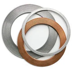
Kammprofile Gasket
What Are Kammprofile Gaskets?
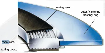
A Kammprofile gasket, also known as a serrated or grooved gasket, is a high-performance seal used in industrial applications that require tight sealing under varying pressures and temperatures. It combines the benefits of soft gasket materials with the strength of metal, providing a reliable sealing option for flanges and other joint types.
The defining feature of a Kammprofile gasket is its metal core, typically made from stainless steel or other corrosion-resistant alloys. The core is machined to have a concentrically serrated profile on both sealing surfaces. These grooves improve sealing efficiency by concentrating the compressive forces applied upon them.
The serrated metal core is covered on one or both sides with a layer of soft sealing material, such as flexible graphite, PTFE (polytetrafluoroethylene), or non-asbestos-compressed fiber. This soft layer helps to create an effective seal by conforming to the flange surfaces and filling any minor irregularities.
A Kammprofile gasket (or “Camprofile”) is manufactured by applying a sealing layer in non-metallic materials (such as graphite, PTFE-Teflon, ceramic fibers, non-asbestos, Mica, etc) or metallic materials (such as aluminum or silver) on both sides of a metal core featuring concentric grooves of 1 mm Cam-Pitch. This sealing product, called also a “grooved metal gasket” or “corrugated metal gasket”, is used for high-pressure and temperature oil & gas applications.
Kammprofile gaskets are used in many industrial, petrochemical, power generation, and nuclear installations (to seal flanges, heat exchangers, superheaters, and, other pressure equipment) and are preferred to Spiral Wound Gaskets for processes with constant high pressure/temperatures requiring strong bolt-loads and remarkable flanged joints’ resistance.
Kammprofile gaskets fit smooth and stock flange surface finish (3.2 to 6.3 μm Ra, i.e. 125-250 RMS).
The common thickness of a Kammprofile gasket is between 2 and 4 mm (3 mm is the most common specification in petrochemical applications).
A Kammprofile gasket offers several benefits, due to its wide sealing area and construction:
- May resist temperatures up to approx. 1000°C (the Kammprofile temperature rating depends on the materials of the metal core and the sealing layer)
- May rate up to 250 bars, which is a considerable pressure rating
- The gasket does not damage the flange surface, due to the protection offered by the sealing layer
- The gasket can absorb fluctuations in temperature and pressure
- It is more tolerant than Spiral Wound Gaskets to improper bolting torques
- Suits both light and heavyweight flanges, even of large sizes
- After assembly, the thickness of the sealing material is extremely low (0.1 - 0.2 mm), thus reducing leaks and failure rates
- The core of a Kammprofile gasket can be re-used after cleaning and fitting the gasket with new layering material. This is critical for expensive applications, such as heat exchanger gaskets that are made of exotic, expensive, materials (Inconel, Monel, Hastelloy, and Cupronickel).
An outer metallic (integral or floating) ring may be added to the gasket to center it during installation on a flange. The sealing layers protect the flange surface and reinforce the seal.
Kammprofile Gasket Types
Overall Design
Kammprofile gaskets come in several types to suit different applications and flange configurations. The variations primarily concern the presence and type of guide rings and the choice of facing material.
| Kammprofile Type | Description | Applications |
|---|---|---|
| Basic | Simplest form: serrated metal core without additional layers or coatings. Core grooves engage directly with flange surfaces. | Smooth, clean flanges with no need for additional compression limiting or flange protection. |
| With Integral Outer Ring | Includes an integral outer guide ring (same material as core) that centers the gasket and acts as a compression stop, preventing over-tightening. | Standard raised-face flanges requiring additional alignment and protection. |
| With Loose Outer Ring | Similar to integral type but with a loose outer ring for easier alignment and installation. The loose ring also is a compression stop. | Raised face and flat face flanges where alignment under bolt tightening is a concern. |
| With Inner Ring | Features an inner ring within the gasket’s serrations providing additional radial strength, preventing inward buckling of the soft sealing layer. | Protection against corrosive or erosive media and applications involving turbulent flow. |
| With Both Inner and Outer Rings | Combines both rings, offering centering, protection from over-compression, and enhanced sealing against erosion and corrosion. | Raised face, flat face, and male-female flanges in more demanding operational conditions. |
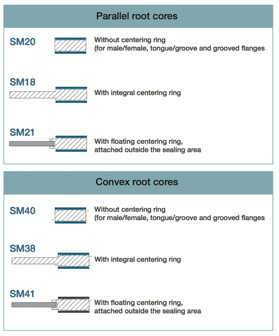
Parallel vs. Convex Core
Kammprofile gaskets can be designed with different core profiles to improve their sealing under specific conditions. The two main variations are parallel root cores and convex root cores, each affecting the gasket’s compressibility, recovery, and sealing performance.
| Feature | Parallel Root Core | Convex Root Core |
|---|---|---|
| Design | Serrations are straight and parallel, creating a uniform profile with consistent groove depth and width. | Serrations have a convex curve at the root of each groove, increasing contact pressure at the peaks. |
| Advantages | Even compressive force distribution, good recovery and resilience under fluctuating loads and temperatures. | Higher sealing efficiency under lower bolt loads, improved resilience and stress distribution, reduced leakage risk. |
| Applications | Standard flange connections with relatively consistent pressures and temperatures; sealing liquids and gases. | Restricted bolt loading, lightweight flanges, lower compressive forces, irregular or damaged flange surfaces. |
Kammprofile Gasket Materials
Metal Core Materials
The core material of a Kammprofile gasket shall match the material of the piping system
| Kammprofile Core Materials | DINDesignation | DIN Material Number | AISI ASTM UNSDesignation | British StandardDesignation | HardnessHB/HV | Temperature in C°Min. Max. | Density in gr/cm3 | | -------------------------- | ---------------- | ------------------- | ------------------------ | --------------------------- | ------------- | -------------------------- | ----------------- | ---- | | Soft Iron | - | - | - | - | 90 - 100 | - 60 | 500 | 7.85 | | Steel (LCS) | RSt. 37.2 | 1.0038 | - | - | 100 - 130 | - 40 | 500 | 7.85 | | Stainless Steel 304 | X5 CrNi 1810 | 1.4301 | 304 | 304S15/16/31 | 130 - 180 | -250 | 550 | 7.9 | | Stainless Steel 304 L | X2CrNi 1911 | 1.4306 | 304L | 304S11 | 130 - 190 | -250 | 550 | 7.9 | | Stainless Steel 309 | X15CrNiSi 2012 | 1.4828 | 309 | 309S24 | 130 - 190 | -100 | 1000 | 7.9 | | Stainless Steel 316 L(1) | X2CrNiMo 1713 | 1.4404 | 316L | 316S11/13 | 130 - 190 | -100 | 550 | 7.9 | | Stainless Steel 316 Ti | X6CrNiMoTi 1712 | 1.4571 | 316Ti | 320S31 | 130 - 190 | -100 | 550 | 7.8 | | Stainless Steel 321 | X6CrNiTi 1810 | 1.4541 | 321 | 321S12/49/87 | 130 - 190 | -250 | 550 | 7.9 | | Stainless Steel 347 | X6CrNiNb 1810 | 1.4550 | 347 | 347S31 | 130 - 190 | -250 | 550 | 7.9 | | Aluminium | Al 99,5 | 3.0255 | - | - | 20 - 23 | -250 | 300 | 2.73 | | Silver | - | - | - | - | 28* | -250 | 750 | 10.5 | | Copper | - | 2.0090 | - | - | 50 - 80 | -250 | 400 | 8.9 | | Nickel 200 | Ni 99,2 | 2.4066 | N02200 | 3072-76 NA11 | 90 - 120 | -250 | 600 | 8.9 | | Monel 400 ® | NiCu 30 Fe | 2.4360 | N04400 | 3072-76 NA13 | 110 - 150 | -125 | 600 | 8.8 | | Inconel 600 ® | NiCr 15 Fe | 2.4816 | N06600 | 3072-76 NA14 | 120 - 180 | -100 | 950 | 8.4 | | Incoloy 800 ® | X10NiCrAITi 3220 | 1.4876 | N08800 | 3072-76 NA15 | 140 - 220 | -100 | 850 | 8.0 | | Incoloy 825 ® | NiCr 21 Mo | 2.4858 | N08825 | 3072-76 NA16 | 120 - 180 | -100 | 450 | 8.14 | | Hastelloy B2 ® | NiMo 28 | 2.4617 | N10665 | - | 170 - 230 | -200 | 450 | 9.2 | | Hastelloy C276 ® | NiMo16Cr15W | 2.4819 | N10276 | - | 170 - 230 | -200 | 450 | 8.9 | | Titanium | Ti 99,8 | 3.7025 | - | - | 110 - 140 | -250 | 350 | 4.5 |
Sealing Layer
The most common layer materials for Kammprofile gaskets are graphite and PTFE (Teflon). The advantages of a graphite layering material are:
- Excellent gas tightness qualities
- Non-aging properties
- Very good chemical resistance
- Resistance to high (fluctuating) temperatures and pressures
PTFE is also used due to its excellent chemical resistance, resistance to temperatures up to 250°C, and excellent sealing properties for gas applications.
| Sealing Layer Material for Kammprofile | Temperature in C°Min. Max. | Max. operating pressure in Bars | Gas tightness | Recommended Application | | -------------------------------------- | -------------------------- | ------------------------------- | ------------- | ----------------------- | ---------------- | | Graphite | -200 | 550 | 250 | Good | Aggressive media | | PTFE (Teflon ® ) | -200 | 250 | 100 | Good | Aggressive media | | Non-asbestos | -100 | 250 | 100 | Good | Gas and liquids | | Silver | -200 | 750 | 250 | Good | Aggressive media |
Kammprofile Gasket Dimensions
Kammprofile Gasket Class 150-400
Kammprofile gasket dimensions for AMSE B16.5 flanges

| NPS | d1 | d2 | d3 | | --- | ----- | ----- | ----- | ----- | ----- | | 150 | 300 | 400 | | 1/2 | 23 | 33.3 | 44.4 | 50.8 | 50.8 | | 3/4 | 28.6 | 39.7 | 53.9 | 63.5 | 63.5 | | 1 | 36.5 | 47.6 | 63.5 | 69.8 | 69.8 | | 1¼ | 44.4 | 60.3 | 73 | 79.4 | 79.4 | | 1½ | 52.4 | 69.8 | 82.5 | 92.1 | 92.1 | | 2 | 69.8 | 88.9 | 101.6 | 108 | 108 | | 2½ | 82.5 | 101.6 | 120.6 | 127 | 127 | | 3 | 98.4 | 123.8 | 133.4 | 146.1 | 146.1 | | 3½ | 111.1 | 136.5 | 158.8 | 161.9 | 158.7 | | 4 | 123.8 | 154 | 171.5 | 177.8 | 174.6 | | 5 | 150.8 | 182.6 | 193.7 | 212.7 | 209.5 | | 6 | 177.8 | 212.7 | 219.1 | 247.7 | 244.5 | | 8 | 228.6 | 266.7 | 276.2 | 304.8 | 301.6 | | 10 | 282.6 | 320.7 | 336.5 | 358.8 | 355.6 | | 12 | 339.7 | 377.8 | 406.4 | 419.1 | 415.9 | | 14 | 371.5 | 409.6 | 447.7 | 482.6 | 479.4 | | 16 | 422.3 | 466.7 | 511.2 | 536.6 | 533.4 | | 18 | 479.4 | 530.2 | 546.1 | 593.7 | 590.5 | | 20 | 530.2 | 581 | 603.2 | 650.9 | 644.5 | | 24 | 631.8 | 682.6 | 714.4 | 771.5 | 765.2 |
All values in millimeters
Kammprofile Gasket Class 600-2500
Kammprofile gasket dimensions for AMSE B16.5 flanges
| NPS | d1 | d2 | d3 | | --- | ----- | ----- | ----- | ----- | ----- | ----- | | 600 | 900 | 1500 | 2500 | | 1/2 | 23 | 33.3 | 50.8 | 60.3 | 60.3 | 66.7 | | 3/4 | 28.6 | 39.7 | 63.5 | 66.7 | 66.7 | 73 | | 1 | 36.5 | 47.6 | 69.8 | 76.2 | 76.2 | 82.5 | | 1¼ | 44.4 | 60.3 | 79.4 | 85.7 | 85.7 | 101.6 | | 1½ | 52.4 | 69.8 | 92.1 | 95.2 | 95.2 | 114.3 | | 2 | 69.8 | 88.9 | 108 | 139.7 | 139.7 | 142.8 | | 2½ | 82.5 | 101.6 | 127 | 161.9 | 161.9 | 165.1 | | 3 | 98.4 | 123.8 | 146.1 | 165.1 | 171.5 | 193.7 | | 3½ | 111.1 | 136.5 | 158.7 | … | … | … | | 4 | 123.8 | 154 | 190.5 | 203.2 | 206.4 | 231.7 | | 5 | 150.8 | 182.6 | 238.1 | 244.5 | 250.8 | 276.2 | | 6 | 177.8 | 212.7 | 263.5 | 285.8 | 279.4 | 314.3 | | 8 | 228.6 | 266.7 | 317.5 | 355.6 | 349.3 | 384.1 | | 10 | 282.6 | 320.7 | 369.9 | 431.8 | 431.8 | 473 | | 12 | 339.7 | 377.8 | 454 | 495.3 | 517.5 | 546.1 | | 14 | 371.5 | 409.6 | 488.9 | 517.5 | 574.7 | … | | 16 | 422.3 | 466.7 | 561.9 | 571.5 | 638.1 | … | | 18 | 479.4 | 530.2 | 609.6 | 635 | 701.7 | … | | 20 | 530.2 | 581 | 679.5 | 695.3 | 752.4 | … | | 24 | 631.8 | 682.6 | 787.4 | 835 | 898.5 | … |
All values in millimeters
Jacketed Gasket
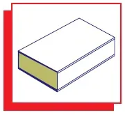
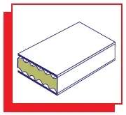
What Is a Jacketed Gasket?
A jacketed gasket is a composite gasket used in industrial piping, vessels, and heat exchangers, designed for a range of temperatures, pressures, and chemical conditions. It consists of a soft, compressible filler material enclosed in a metal jacket. The metal jacket provides mechanical strength, chemical resistance, and thermal stability, while the filler material conforms to the flange surfaces and provides an effective seal.
Jacketed gaskets can be fully jacketed, partially jacketed, or single-jacketed, depending on the application requirements:
- Fully Jacketed Gaskets: The filler material is completely enclosed in the metal jacket, offering maximum protection and strength. This type is typically used in applications involving high pressures and temperatures.
- Partially Jacketed Gaskets: Only certain sections of the filler material are covered by the metal jacket. This design is chosen based on specific sealing and operational needs, providing a balance between the compressibility of the filler and the strength of the metal jacket.
- Single-Jacketed Gaskets: The metal jacket covers only one face and the inside edge of the gasket. This type is suitable for applications where the gasket needs extra strength on one side, such as in narrow flanges.
A metal jacket gasket requires flat face flanges with a smooth face finish to seal effectively.
The size range and thickness tolerances for this type of gasket are covered by ASME B16.21 specification:
- OD: Less than 5,000mm
- Thickness: 2~8mm with tolerance +0.03 inch. to -0.000 inch (+0.8mm, -0.0mm)

Jacketed Gasket Materials
Jacketed gaskets use the following materials:
- Metal Jacket: Common materials for the jacket include stainless steel, aluminum, copper, Monel, and Inconel. The choice of metal is based on the required thermal, chemical, and mechanical properties.
- Filler Material: Typical fillers include flexible graphite, PTFE (Polytetrafluoroethylene), non-asbestos compressed fiber, and ceramic. The filler selection depends on the sealing requirements, including chemical compatibility and temperature resilience.
The table shows the recommended temperature range for common metal jacket materials:
| Jacket Materials | Hardness HB | Temp.℃ |
|---|---|---|
| Carbon Steel | 90 | -60~+450 |
| 304 (L) | 130 | -270~+550 |
| 316 (L) | 130 | -270~+550 |
| 321 | 130 | -270~+550 |
| Monel | 110 | -60~+500 |
| Inconel | 90 | -60~+600 |
| AL | 30 | -250~+300 |
| CU | 80 | -250~+400 |
Jacketed Gasket Types
The two main types of metal jacketed gaskets are the single and the double jacket designs. Besides these two basic types, other designs are available on the market as illustrated below:
 | Double Jacketed Corrugated- soft fillerReduced contact area, enhances compression characteristics, suitable for uneven flanges. |
|---|---|
 | Double Jacketed Corrugated- metal fillerUsually stainless outer casing with soft iron filler ring.Core material available St. St. -304.316L.321Soft iron, Monel, Inconel |
 | Single Corrugated- asbestos rope fillerTypically used on very poor or pitted flanges, low bolt loading requirement. |
 | Metal Jacket Laminates- soft fillerCombines flexible graphite with stainless steel core material |
 | Solid metal ring machined on each contact face to provide a serrated surface finish covered with Graphite.PTFE Nonas or Asbestos. |
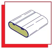 | Double Jacketed - soft fillerUsed on high-temperature pressure applications or where corrosion problems may exist |
|---|---|
 | Single Jacketed - metal filler- partly enclosedVery seldom used, old design. Used in applications where poor or pitted flanges exist on one face. |
 | Single Jacketed - Soft filler- partly enclosedUsed on narrow flanges |
 | Single Jacketed - Soft filler- open outside edgeUsed in narrow flanges, protection of filler cleared for by casing |
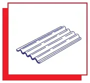 | Single Corrugated - no fillerUsed mainly in valve applications, small recess gap. Sometimes referred to as the Taylor ring. |
Jacketed Gasket Dimensions
Jacket Gasket Class 150-400
 Jacketed gasket dimension
| NPS | d1 | d2 |
|---|---|---|
| 150 | 300 | 400 |
| 1/2 | 23.8 | 44.5 |
| 3/4 | 31.8 | 54 |
| 1 | 36.5 | 63.5 |
| 1¼ | 46 | 73 |
| 1½ | 52.4 | 82.6 |
| 2 | 73.2 | 101.6 |
| 2½ | 85.9 | 120.6 |
| 3 | 107.8 | 133.4 |
| 4 | 131.8 | 171.5 |
| 5 | 152.4 | 193.8 |
| 6 | 190.5 | 219.1 |
| 8 | 238.3 | 276.3 |
| 10 | 285.8 | 336.6 |
| 12 | 342.9 | 406.4 |
| 14 | 374.7 | 447.7 |
| 16 | 425.5 | 511.2 |
| 18 | 489 | 546.1 |
| 20 | 533.4 | 603.3 |
| 24 | 641.4 | 714.4 |
| NPS | d1 | 150 |
Jacket Gasket Class 600-2500
Jacketed gasket dimensions for AMSE B16.5 flanges
| NPS | d1 | d2 | | --- | ----- | ----- | ----- | ----- | ----- | | 600 | 900 | 1500 | 2500 | | 1/2 | 23.8 | 50.8 | 60.4 | 60.4 | 66.8 | | 3/4 | 31.8 | 63.5 | 66.7 | 66.7 | 73.1 | | 1 | 36.5 | 69.9 | 76.2 | 76.2 | 82.5 | | 1¼ | 46 | 79.4 | 85.8 | 85.8 | 101.6 | | 1½ | 52.4 | 92.1 | 95.3 | 95.3 | 114.3 | | 2 | 73.2 | 108 | 139.7 | 139.7 | 143 | | 2½ | 85.9 | 127 | 161.9 | 161.9 | 165.1 | | 3 | 107.8 | 146.1 | 165.1 | 171.5 | 193.8 | | 4 | 131.8 | 190.5 | 203.2 | 206.5 | 231.9 | | 5 | 152.4 | 238.2 | 244.6 | 250.9 | 276.3 | | 6 | 190.5 | 263.6 | 285.8 | 279.4 | 314.5 | | 8 | 238.3 | 317.5 | 355.6 | 349.3 | 384.3 | | 10 | 285.8 | 396.9 | 431.8 | 431.8 | 473.2 | | 12 | 342.9 | 454.1 | 495.3 | 517.6 | 546.1 | | 14 | 374.7 | 489 | 517.6 | 574.7 | … | | 16 | 425.5 | 562 | 571.5 | 638.2 | … | | 18 | 489 | 609.6 | 635 | 701.8 | … | | 20 | 533.4 | 679.5 | 695.5 | 752.5 | … | | 24 | 641.4 | 787.4 | 835.1 | 898.6 | … |
How to Order a Metal Jacketed Gasket
The following information should be provided to the gasket supplier to order a jacket gasket properly:
- Outside diameter
- Inside diameter (NPS)
- Shape per standard index
- Type Number
- Thickness
- Materials (metal or metal filler)
- Bar size
- Radii
- Distance from the centerline of the gasket to the centerline of the bars
Watch the Video

Frequently Asked Questions
What is the maximum temperature for a spiral wound gasket?
Spiral wound gaskets with flexible graphite filler can operate up to approximately 500°C (930°F) in oxidizing atmospheres and up to 650°C (1200°F) in non-oxidizing/reducing environments. With PTFE filler, the limit drops to about 260°C (500°F). For temperatures above 650°C, metal ring joint (RTJ) gaskets or Kammprofile gaskets with metal-only contact are recommended.
What determines the correct gasket thickness for a flanged joint?
For spiral wound gaskets, the standard thickness is 4.5 mm (with inner/outer rings) per ASME B16.20. For sheet gaskets (ASME B16.21), common thicknesses are 1.5 mm, 2.0 mm, and 3.0 mm. Thinner gaskets (1.5 mm) provide better blowout resistance and lower creep, while thicker gaskets (3.0 mm) compensate for flange surface irregularities. As a rule: use the thinnest gasket that will seal properly given the flange face condition.
What is the difference between a metallic and a non-metallic gasket?
Non-metallic gaskets (rubber, PTFE, compressed fiber) are used for low-pressure, low-temperature applications and flat-face (FF) flanges. Semi-metallic gaskets (spiral wound, Kammprofile) combine a metal structure with soft filler material for medium-to-high pressure with raised-face (RF) flanges. Metallic gaskets (ring joint, solid metal) are pure metal, used for the highest pressures and temperatures with RTJ flanges (Class 600+).
When is a ring type joint (RTJ) gasket required instead of a spiral wound?
RTJ gaskets are required for Class 900 and above (per most project specifications), and for any application requiring metal-to-metal sealing: high-pressure/high-temperature service, subsea, sour (H2S) service, and critical applications where zero-leakage is mandatory. RTJ gaskets seat into machined grooves on the flange face and provide the highest sealing reliability, but require better flange alignment and higher bolt loads than spiral wound gaskets.
Leave a Comment
Have a question or feedback? Send us a message.
Previous Comments
Thanks for sharing this informative blog..!
I appreciate your blog because it is great
Smooth finish is used with a metallic gasket whereas a serrated finish is used with a non-metallic gasket. The soft material of gaskets is set in this serration and prevents liquid or gas from passing from the flange joint.
Thank you for your comment, correct
Can anyone help me on the ASTM Grade for S32760 Spiral Wound Gaskets. Whether it is A240 or A479 or A182 etc.