Stub End: Types & Sizes (ASME B16.9)
Stub End
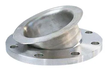
What Is a Stub End?
A stub end is a short length of pipe with one flared end, used together with a lap joint flange to create a flanged pipe connection. The flared end seats against the flange face while the plain end butt-welds to the pipeline. The lap joint flange slides freely over the stub end and does not need to be welded, so the flange can be removed for maintenance or system modifications without cutting any welds.
This two-piece arrangement has expanded well beyond low-pressure service. Modern stub end assemblies now handle high-pressure applications across process, offshore, and power piping.

The flared end profile matches the facing of the lap joint flange, giving a smooth, continuous sealing surface. This end receives the butt weld to the pipe. The plain (unflarred) end has an OD that matches the flange bore, sliding through the lap joint flange with a close fit. Stub ends are produced in carbon steel, stainless steel, duplex, super duplex, and nickel alloys to match whatever the pipeline carries.
Stub ends come in three types (A, B, and C), each with a different hub geometry and lap profile. The differences are covered in detail below.
The stub end and lap joint flange combination delivers three practical benefits in the field:
| Benefit | How It Works |
|---|---|
| Easy assembly and disassembly | The flange slips off without cutting welds, saving hours during turnarounds and cleaning cycles in process plants. |
| Lower material cost | Only the stub end must match the pipe alloy. The flange never contacts process fluid, so it can be plain carbon steel. |
| Free bolt-hole alignment | The lap joint flange rotates freely around the stub end, eliminating the alignment headaches common with fixed weld neck flanges. |
During installation, the stub end is butt-welded to the pipe using standard WPS-qualified procedures. A gasket seals the interface between the flared end and the mating flange face. All three components (stub end, lap joint flange, and pipe) must share compatible NPS, schedule, and end-prep dimensions.
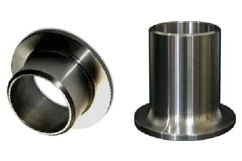
Stub End with Lap Joint Flange
A stub end paired with a lap joint flange replaces a weld neck flange for flanged connections. Two parts do the work:
-
The Stub End is a pipe section with one end flared outward by a flaring machine, then trimmed to length. The opposite end butt-welds to a pipe of the same NPS, material, and wall thickness.
-
The Lap Joint Flange slips loosely over the stub end. When bolted to the mating flange, it compresses the flared end against the opposing flange face, forming the seal.
This assembly provides alignment flexibility, easy access for inspection or modification, and compatibility with lined or non-metallic pipe. It is a practical choice wherever frequent disassembly is expected.
Benefits of Using Lap Joint Stub Ends
Two benefits drive most stub end selections over weld neck flanges:
- Lower total cost of the flanged joint. The lap joint flange can be a lower grade than the stub end and pipe, cutting the total weight of high-grade alloy in the joint.
Example:
For an SS316 pipe, instead of a full 316 welding neck flange, a combination of an SS316 stub end and a carbon steel lap joint flange does the same job. The total weight of SS316 drops, and so does the cost.
Stub ends minimize high-grade material weight across stainless, duplex, and nickel alloy piping. The larger the diameter and pressure class, the greater the savings.
- Easier flange installation. The lap joint flange rotates freely on the pipe, simplifying bolt-hole alignment with the mating flange.
Beyond these two primary reasons, the stub end / lap joint arrangement offers additional practical gains:
| Advantage | Detail |
|---|---|
| Simplified maintenance | The flange slips off without cutting pipe. No hot work permit needed just to remove a flange for inspection, saving time and labor. |
| Weight reduction | Stub ends weigh less than weld neck flanges of the same NPS and class, a real factor on offshore platforms, pipe racks, and suspended systems. |
| Material match at the seal face | The sealing surface is the same alloy as the pipe, so corrosion resistance at the gasket contact zone matches the rest of the system. |
| Thermal expansion tolerance | The lap joint flange can slide slightly over the stub end, absorbing pipe movement without concentrating stress at the joint. |
| Reduced leak risk | Because the seal face alloy matches the pipe, gasket compatibility and corrosion resistance stay consistent across the joint. |
Applicable Specifications
Stub ends are manufactured and inspected against several overlapping codes and standards:
ASME Standards
ASME B16.9 covers factory-made wrought buttwelding fittings from NPS 1/2 through NPS 48 (DN 15 through DN 1200). It defines dimensions, tolerances, and material requirements for stub ends. ASME B16.5, while focused on flanges, includes provisions for stub end use with lap joint flanges across pressure classes.
MSS Standards
MSS SP-43, “Wrought and Fabricated Butt-Welding Fittings for Low Pressure, Corrosion Resistant Applications,” supplements the ASME standards. It details dimensions and requirements for stainless steel and alloy stub ends in Types A, B, and C, aimed at corrosion-resistant, lower-pressure service.
International Standards
ISO 15590-3 covers fittings for petroleum and natural gas pipeline transportation systems, including stub ends.
Industry-Specific Standards
Petroleum, chemical, and pharmaceutical sectors often impose project specifications that go beyond the general codes, particularly for exotic alloys, elevated temperatures, or cyclic-pressure service.
ASA/ANSI VS. MSS Stub Ends
ASA (American Standards Association) was the predecessor of ANSI (American National Standards Institute). The term ASA still appears in legacy specifications, but both refer to the same lineage of standards.
ASA (ANSI) Stub Ends
ASA (ANSI) stub ends follow the dimensional requirements of ANSI B16.9 for factory-made wrought buttwelding fittings. They cover both seamless and welded construction, in multiple materials and sizes, for use with lap joint flanges. These are the general-purpose stub ends found across most piping systems.
MSS Stub Ends
MSS stub ends follow MSS SP-43, which focuses on lightweight stainless steel buttwelding fittings. SP-43 defines Types A, B, and C, with an emphasis on corrosion-resistant service at moderate pressures.
Key Differences
| Aspect | ASA/ANSI Stub Ends | MSS Stub Ends |
|---|---|---|
| Scope | Broad: multiple industries, materials, and pressure ratings | Focused on stainless steel and alloys for corrosion-resistant, lower-pressure service |
| Type designations | Covers a range of designs without explicit A/B/C type labels | Explicitly defines Types A, B, and C with distinct geometry for each |
| Typical selection driver | Standard piping systems, higher-pressure service | Corrosion resistance, lighter wall thickness, cost optimization on alloy piping |
The choice between ASA/ANSI and MSS stub ends depends on the piping specification, required material, pressure-temperature rating, and project code compliance.
Stub End Types
Stub ends are available in three types, named “A”, “B”, and “C”.
Each type has a distinct hub and lap geometry that suits different piping conditions.
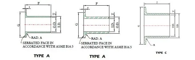
Stub End “Type A”
Type A is the most common stub end configuration and handles the widest range of service conditions.
The hub has a long, tapered profile with a curved radius matching the pipe bore. This gradual transition minimizes turbulence and erosion at the joint. The taper accommodates a range of pipe wall thicknesses, and the overall geometry closely mimics the flow path through a weld neck flange.
Type A stub ends are manufactured in carbon steel, stainless steel, duplex, and nickel alloys to match pipeline requirements. Dimensions follow ASME B16.9, guaranteeing compatibility with standard lap joint flanges.
During installation, the straight end of the stub end is butt-welded to the pipe with the flared end (the lap) precisely aligned to the pipe terminus. The lap joint flange then slips over and seats against the back of the flare. When bolted to the mating flange, the assembly compresses the flare to create the seal.
| Characteristic | Type A Detail |
|---|---|
| Flow path | Smooth tapered transition, comparable to a weld neck flange |
| Flange rotation | Full 360-degree rotation for bolt-hole alignment |
| Maintenance access | Flange removes without cutting welds |
| Cost position | Economical when the flange can be a lower-grade material |
| Pressure range | Suitable for both low- and high-pressure service |
Stub End “Type B” (MSS SP-43 Type B)
Type B has a squared-off lap instead of a tapered hub. The flat lap face sits flush against the back face of the lap joint flange, and the OD of the lap matches the pipe OD directly.
The welding end of a Type B stub end typically has a thinner wall than a Type A, because Type B targets lighter pipe schedules (Sch 5S, 10S). Dimensions follow MSS SP-43. Materials include carbon steel, stainless steel, and alloys, selected to match the pipeline.
Installation mirrors Type A: the stub end is butt-welded to the pipe with the squared lap facing outward, then the lap joint flange slides over and bolts up.
| Characteristic | Type B Detail |
|---|---|
| Lap geometry | Squared-off, flush face |
| Wall thickness | Thinner, matched to lighter pipe schedules |
| Fabrication | Simpler geometry, lower manufacturing cost |
| Typical service | Lower pressure and temperature, water treatment, chemical processing, general industrial |
| Pressure/temperature limits | Not suited for demanding high-pressure or high-temperature service |
Verify that the stub end material and dimensions are compatible with both the pipe schedule and the process fluid before specifying Type B.
Stub End “Type C” (Lap-Joint/Slip-On Flanges)
Type C uses a separate lap collar that is independent of the stub end body. The stub end itself has a straight-cut terminus where the collar sits. This two-piece construction allows the collar position to be adjusted along the stub end length before final assembly.
Materials follow the same options as Types A and B. Because of the adjustable collar, dimensions can be tailored to non-standard piping layouts.
Installation follows the same butt-weld procedure for the stub end body. The separate collar is then slid into position, and the lap joint flange seats against it. When bolted, the flange compresses the collar to form the seal.
| Characteristic | Type C Detail |
|---|---|
| Collar | Separate piece, adjustable position |
| Best use case | Systems requiring precise alignment or non-standard configurations |
| Maintenance | Same easy disassembly as Types A and B |
| Customization | Collar and stub end can be tailored independently |
| Lead time and cost | Typically longer lead time and higher cost than Types A or B due to the two-piece construction |
Confirm that the collar and stub end are fully compatible with the lap joint flange dimensions and meet the applicable project specification.
Differences Between Stub End Type A, B, C
The main differences between stub end Type A, B, and C revolve around their design features, compatibility with various flange types, and specific applications:
| Feature | Type A | Type B | Type C |
|---|---|---|---|
| Geometry | Long tapered hub; smooth flow transition | Squared-off lap; aligns with backing flange face | Separate lap/collar; adjustable fit |
| Flange Compatibility | Wide range of flange sizes | Lap joint flanges for lighter pipe schedules | Adjustable with lap joint flanges for unique configurations |
| Application | Versatile; various industries and piping schedules | Lighter pipes; less demanding conditions | Precise alignment; challenging piping configurations |
| Installation | Tapered hub accommodates a range of piping schedules | Simplified fabrication; specific dimensional compatibility | Lap collar positioned independently for alignment flexibility |
| Pipe Schedules | Wide range of wall thicknesses | Lighter schedules | Customizable |
Short vs. Long Pattern Stub Ends
Short pattern and long pattern stub ends differ in overall length, which affects flow transition and the types of systems they fit.
 Short pattern (MSS) and long pattern stub ends (ASA)
Short Pattern (MSS)
Short pattern stub ends have a compact body length. They pair with standard lap joint flanges and work well where axial space is tight. The shorter hub does not provide the same gradual flow transition as the long pattern, so they are most common in moderate-pressure, moderate-temperature service with slip-on or lap joint flanges.
Long Pattern (ASA/ANSI)
Long pattern stub ends have an extended hub that creates a smoother flow transition from pipe to flange face, closely approximating the hydraulic profile of a weld neck flange. This makes them the better choice for high-pressure, high-temperature, or erosion-sensitive service. They pair with lap joint flanges where the system needs the alignment flexibility of a lap joint but the flow performance of a welding neck.
Selection Guidance
| Factor | Short Pattern (MSS) | Long Pattern (ASA/ANSI) |
|---|---|---|
| Available space | Tight layouts, close-coupled flanges | Standard or generous layout spacing |
| Flow sensitivity | Moderate; acceptable turbulence at the joint | Low turbulence, smooth transition |
| Pressure/temperature | Low to moderate | Moderate to high |
| Maintenance frequency | Either pattern allows equal flange access | Either pattern allows equal flange access |
Choose the pattern based on the project piping specification, available space, and the pressure-temperature-erosion demands of the service.
End Types for Stub Ends
Stub ends can be ordered with different end finishes depending on the connection method:
Beveled Ends
Beveled ends have an angled cut (typically 30 or 37.5 degrees) at the welding end, matching the pipe bevel for full-penetration butt welds. This is the standard end type for most piping systems, especially in high-pressure service where weld integrity matters most.
Squared Ends
Squared ends are cut flat across, creating a perpendicular face. They are used where the stub end butts against a flat surface or another squared end. This simpler preparation works for socket-type or fillet-weld connections and for lighter-duty fabrication.
Flanged Ends
Flanged end stub ends have an integral flange forged or machined as part of the fitting, allowing a bolted connection without a separate lap joint flange. This configuration suits systems requiring frequent dismantling for inspection or cleaning.
Grooved Ends
Grooved ends have a machined circumferential groove that accepts a grooved coupling or gasket. These stub ends connect into grooved piping systems, providing fast assembly and disassembly at moderate pressures. Fire protection systems and commercial HVAC installations commonly use this end type.
Threaded Ends (Male Only)
Threaded end stub ends carry male threads for engagement with female-threaded valves, fittings, or pipe. They allow assembly and disassembly without welding and suit low- to moderate-pressure systems where threaded connections are specified.
Stub End Materials
The buttweld fittings material specifications apply also to stub ends.
The table summarizes the most common carbon, stainless, duplex, and nickel-alloy grades. Note that other materials may be used to manufacture stub ends, namely Cupronickel, Titanium, and Copper.
For details about the chemical composition and mechanical properties of BW fittings, please consult this article.
| ASTM Materials for Stub Ends | Grade | UNS Equivalent |
|---|---|---|
| Carbon Steel[ASTM A234 WPB] | WPA/WPB/WPC | K03006 |
| Stainless Steel[ASTM A403] | 304/304L | S30403 |
| 304H | S30409 | |
| 316/316L | S31603 | |
| 316H | S31609 | |
| 317L | S31703 | |
| 904L | N08904 | |
| 309S/H | S30908 | |
| 310S | S31008 | |
| 321 | S32100 | |
| 6XN | N08367 | |
| 20CB | N08020 | |
| 347 | S34709 | |
| 254SMO | S31254 | |
| Duplex /Super Duplex[ASTM A815] | 2205 | S31803/S32205 |
| Zeron 100 | S32760 | |
| 2507 | S32750 | |
| 410 | S41000 | |
| Nickel Alloys[ASTM A366 - replaced by ASTM A462] | HC22 | N06022 |
| HB-3 | N10675 | |
| HG3 | N06985 | |
| HX | N06002 | |
| HC2000 | N06200 | |
| HC276 | N10276 | |
| NCI | N06600 | |
| NC | N04400 | |
| N | N02200 | |
| NL | N02201 | |
| NCMC | N06625 | |
| NICMC | N08825 | |
| NIC10 | N08810 | |
| NIC11 | N08811 |
Stub Ends Dimensions
The charts below show the MSS and ANSI stub end dimensions in inches.
Stub End Length and Lap Dimensions
| NPS | MSS Stub End | ANSI Stub End | Pipe OD | Lap OD | Radius |
|---|---|---|---|---|---|
| 1/2 | 2 | 3 | 0.84 | 1.35-1.38 | 1/8 |
| 3/4 | 2 | 3 | 1.05 | 1.66-1.69 | 1/8 |
| 1 | 2 | 4 | 1.315 | 1.7-2 | 1/8 |
| 1 1/4 | 2 | 4 | 1.66 | 2.47-2.5 | 3/16 |
| 1 1/2 | 2 | 4 | 1.9 | 2.85-2.88 | 1/4 |
| 2 | 2.5 | 6 | 2.375 | 3.59-3.62 | 5/16 |
| 2 1/2 | 2.5 | 6 | 2.875 | 3.9-4.12 | 5/16 |
| 3 | 2.5 | 6 | 3.5 | 4.97-5 | 3/8 |
| 3 1/2 | 3 | 6 | 4 | 5.47-5.5 | 3/8 |
| 4 | 3 | 6 | 4.5 | 6.16-6.19 | 7/16 |
| 5 | 3 | 8 | 5.563 | 7.28-7.31 | 7/16 |
| 6 | 3.5 | 8 | 6.625 | 8.47-8.5 | 1/2 |
| 8 | 4 | 8 | 8.625 | 10.59-10.62 | 1/2 |
| 10 | 5 | 10 | 10.75 | 12.69-12.75 | 1/2 |
| 12 | 6 | 10 | 12.75 | 14.94-15 | 1/2 |
| 14 | 6 | 12 | 14 | 16.19-16.25 | 1/2 |
| 16 | 6 | 12 | 16 | 18.44-18.5 | 1/2 |
| 18 | 6 | 12 | 18 | 20.94-21 | 1/2 |
| 20 | 6 | 12 | 20 | 22.94-23 | 1/2 |
| 24 | 6 | 12 | 24 | 27.19-27.25 | 1/2 |
| 26 | 6 | 12 | 26 | 29.19-29.25 | 1/2 |
| 28 | 6 | 12 | 28 | 31.69-31.75 | 1/2 |
| 30 | 6 | 12 | 30 | 33.69-33.75 | 1/2 |
| 32 | 6 | 12 | 32 | 35.94-36 | 1/2 |
| 34 | 6 | 12 | 34 | 37.94-38 | 1/2 |
| 36 | 6 | 12 | 36 | 40.19-40.25 | 1/2 |
| 38 | 6 | 12 | 38 | 42.69-42.75 | 1/2 |
| 40 | 6 | 12 | 40 | 44.69-44.75 | 1/2 |
| 42 | 6 | 12 | 42 | 46.94-47 | 1/2 |
| 44 | 6 | 12 | 44 | 49.19-49.25 | 1/2 |
| 46 | 6 | 12 | 46 | 51.19-51.25 | 1/2 |
| 48 | 6 | 12 | 48 | 53.19-53.25 | 1/2 |
| 50 | 6 | 12 | 50 | 55.19-55.25 | 1/2 |
| 52 | 6 | 12 | 52 | 57.19-57.25 | 1/2 |
| 54 | 6 | 12 | 54 | 59.44-59.5 | 1/2 |
| 60 | 6 | 12 | 60 | 65.44-65.5 | 1/2 |
Pipe Wall Thickness and Flange Thickness by Schedule
| NPS | Sch | Pipe WT (Nom) | Flange thk (Min-Max) |
|---|---|---|---|
| 1/2 | 05S | 0.065 | 0.065-0.127 |
| 1/2 | 10S | 0.083 | 0.083-0.145 |
| 1/2 | 40S | 0.109 | 0.109-0.171 |
| 1/2 | 80S | 0.147 | 0.147-0.209 |
| 3/4 | 05S | 0.065 | 0.065-0.127 |
| 3/4 | 10S | 0.083 | 0.083-0.145 |
| 3/4 | 40S | 0.113 | 0.113-0.175 |
| 3/4 | 80S | 0.154 | 0.154-0.216 |
| 1 | 05S | 0.065 | 0.065-0.127 |
| 1 | 10S | 0.109 | 0.109-0.171 |
| 1 | 40S | 0.133 | 0.133-0.195 |
| 1 | 80S | 0.179 | 0.179-0.241 |
| 1 1/4 | 05S | 0.065 | 0.065-0.127 |
| 1 1/4 | 10S | 0.109 | 0.109-0.171 |
| 1 1/4 | 40S | 0.14 | 0.14-0.202 |
| 1 1/4 | 80S | 0.191 | 0.191-0.253 |
| 1 1/2 | 05S | 0.065 | 0.065-0.127 |
| 1 1/2 | 10S | 0.109 | 0.109-0.171 |
| 1 1/2 | 40S | 0.145 | 0.145-0.207 |
| 1 1/2 | 80S | 0.2 | 0.2-0.262 |
| 2 | 05S | 0.065 | 0.065-0.127 |
| 2 | 10S | 0.109 | 0.109-0.171 |
| 2 | 40S | 0.154 | 0.154-0.216 |
| 2 | 80S | 0.218 | 0.218-0.28 |
| 2 1/2 | 05S | 0.083 | 0.083-0.145 |
| 2 1/2 | 10S | 0.12 | 0.12-0.182 |
| 2 1/2 | 40S | 0.203 | 0.203-0.265 |
| 2 1/2 | 80S | 0.276 | 0.276-0.338 |
| 3 | 05S | 0.083 | 0.083-0.145 |
| 3 | 10S | 0.12 | 0.12-0.182 |
| 3 | 40S | 0.216 | 0.216-0.278 |
| 3 | 80S | 0.3 | 0.3-0.362 |
| 3 1/2 | 05S | 0.083 | 0.083-0.145 |
| 3 1/2 | 10S | 0.12 | 0.12-0.182 |
| 3 1/2 | 40S | 0.226 | 0.226-0.238 |
| 3 1/2 | 80S | 0.318 | 0.318-0.38 |
| 4 | 05S | 0.083 | 0.083-0.145 |
| 4 | 10S | 0.12 | 0.12-0.182 |
| 4 | 40S | 0.237 | 0.237-0.299 |
| 4 | 80S | 0.337 | 0.337-0.399 |
| 5 | 05S | 0.109 | 0.109-0.171 |
| 5 | 10S | 0.134 | 0.134-0.196 |
| 5 | 40S | 0.258 | 0.258-0.32 |
| 5 | 80S | 0.375 | 0.375-0.437 |
| 6 | 05S | 0.109 | 0.109-0.171 |
| 6 | 10S | 0.134 | 0.134-0.196 |
| 6 | 40S | 0.28 | 0.28-0.342 |
| 6 | 80S | 0.432 | 0.432-0.494 |
| 8 | 05S | 0.109 | 0.109-0.171 |
| 8 | 10S | 0.148 | 0.148-0.21 |
| 8 | 40S | 0.322 | 0.322-0.384 |
| 8 | 80S | 0.5 | 0.5-0.562 |
| 10 | 05S | 0.134 | 0.134-0.196 |
| 10 | 10S | 0.165 | 0.165-0.227 |
| 10 | 40S | 0.365 | 0.365-0.427 |
| 10 | 80S | 0.5 | 0.5-0.562 |
| 12 | 05S | 0.156 | 0.156-0.218 |
| 12 | 10S | 0.18 | 0.18-0.242 |
| 12 | 40S | 0.375 | 0.375-0.437 |
| 12 | 80S | 0.5 | 0.5-0.562 |
| 14 | 05S | 0.156 | 0.156-0.218 |
| 14 | 10S | 0.188 | 0.188-0.25 |
| 14 | 40S | 0.375 | 0.375-0.437 |
| 14 | 80S | 0.5 | 0.5-0.562 |
| 16 | 05S | 0.165 | 0.165-0.227 |
| 16 | 10S | 0.188 | 0.188-0.25 |
| 16 | 40S | 0.375 | 0.375-0.437 |
| 16 | 80S | 0.5 | 0.5-0.562 |
| 18 | 05S | 0.165 | 0.165-0.227 |
| 18 | 10S | 0.188 | 0.188-0.25 |
| 18 | 40S | 0.375 | 0.375-0.437 |
| 18 | 80S | 0.5 | 0.5-0.562 |
| 20 | 05S | 0.188 | 0.188-0.25 |
| 20 | 10S | 0.218 | 0.218-0.28 |
| 20 | 40S | 0.375 | 0.375-0.437 |
| 20 | 80S | 0.5 | 0.5-0.562 |
| 24 | 05S | 0.218 | 0.218-0.28 |
| 24 | 10S | 0.25 | 0.25-0.312 |
| 24 | 40S | 0.375 | 0.375-0.437 |
| 24 | 80S | 0.5 | 0.5-0.562 |
| 26-60 | 40S | 0.375 | 0.375-0.437 |
| 26-60 | 80S | 0.5 | 0.5-0.562 |
Leave a Comment
Have a question or feedback? Send us a message.
Previous Comments
This is a very amazing blog and I'm very happy to read this blog.
flosil bet this is a very amazing comment and I'm very happy to read this comment.
can i get the drawing / dimensions of 3″ nb ring type joint stub end?
What are the Standards that covers Stub ends bigger than 24″?
It's great to know that rotating the lap joint flange on the pipe makes it easier to line up the bolt holes on the matching flanges. My husband is an industrial worker. He wants to acquire a piece of machinery for his project that can be utilized to fortify the tube's end. I'll advise him to acquire rotating tube beading for the pipe for his project.