Flange Face Types & Finish: RF, RTJ, FF, T&G, M&F
Flange Face
What Is a Flange Face?
The flange face is the machined contact surface where the gasket sits to create a pressure-tight seal between two mating flanges. Its geometry, surface finish, and compatibility with the gasket type are the three factors that determine whether a flanged joint will hold or leak.
The face type dictates gasket selection, bolt load distribution, and the maximum pressure-temperature envelope of the joint. Selecting the wrong face type (or mating incompatible faces) is one of the most common causes of flange leakage in process piping.
Comparison of All Flange Face Types
| Face Type | Sealing Mechanism | Gasket Type | Pressure Classes | Typical Applications |
|---|---|---|---|---|
| FF (Flat Face) | Full-face compression | Full-face soft gaskets | Class 125, 150 | Cast iron, FRP, HVAC, water |
| RF (Raised Face) | Concentrated gasket compression | Ring or spiral wound | Class 150—2500 | General process piping (default) |
| RTJ (Ring Joint) | Metal-to-metal plastic deformation | Metal ring (R, RX, BX) | Class 150—2500 (std. for 600+) | High P/T, oil & gas, wellheads |
| LJ (Lap Joint) | Per stub end face type | Per stub end face | Class 150—600 | Frequent maintenance, exotic alloys |
| T&G (Tongue & Groove) | Confined gasket compression | Confined gasket | Specialty | Chemical, alignment-critical |
| M&F (Male & Female) | Confined gasket in recess | Confined gasket | Specialty | Moderate pressure, alignment needs |
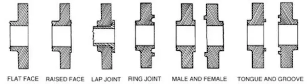
Types of Flange Face
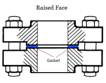
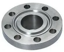
Raised Face Flange (RF)
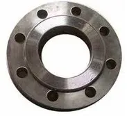
The raised face (RF) is the default flange face per ASME B16.5 for all pressure classes from 150 through 2500. A machined raised ring surrounds the bore, elevating the gasket seating area above the bolt circle. This concentrates bolt load on a smaller area, generating higher gasket seating stress for a tighter seal.
Key characteristics:
- Default face type; buyers must explicitly specify any other face when ordering
- Compatible with the widest range of gaskets: soft (CNAF, rubber), semi-metallic (spiral wound, kammprofile), and metallic (corrugated metal)
- Standard surface finish: 125-250 AARH (3.2-6.3 um Ra) concentric serrated
- Raised face height varies by pressure class (see table below)
| Pressure Class | RF Height | Included in Flange Thickness? |
|---|---|---|
| 150, 300 | 1.6 mm (1/16”) | No (RF is additional to listed thickness) |
| 400, 600 | 6.4 mm (1/4”) | Yes (included in listed thickness) |
| 900, 1500, 2500 | 6.4 mm (1/4”) | Yes (included in listed thickness) |
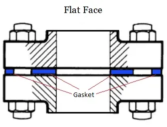
Flat Face Flange (FF)
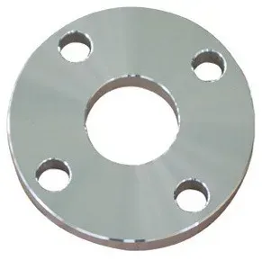
Flat face flanges have no raised area: the gasket contact surface extends across the entire flange face to the bolt holes. The gasket must also be full-face (extending to the bolt holes) to distribute bolt load evenly.
FF flanges are required for brittle materials such as cast iron (ASTM A126), ductile iron, and non-metallic materials (FRP, PVC) that cannot tolerate the concentrated bending moment imposed by a raised face.
| Characteristic | FF Specification |
|---|---|
| Gasket type | Full-face soft gaskets (rubber, PTFE, compressed fiber) |
| Applications | Cast iron pumps, HVAC systems, water/wastewater, FRP piping |
| Pressure range | Low to moderate (typically Class 125, 150) |
| Surface finish | 125-250 AARH (same as RF) |
| Standard | ASME B16.1 (cast iron), ASME B16.5 (steel, must specify) |
Ring Type Joint Flange Face (RTJ)
Ring Type Joint (RTJ) flanges feature a precision-machined groove that accepts a solid metal ring gasket. The ring, made from a material softer than the flange (so that it deforms first), is compressed into the groove under bolt load. This creates a metal-to-metal seal capable of withstanding the highest pressures and temperatures in process piping.
RTJ facing is the standard for ASME Class 600 and above in most oil and gas specifications, and is mandatory for wellhead equipment per API 6A.
| Feature | RTJ Specification |
|---|---|
| Gasket styles | R (octagonal or oval), RX (self-energizing), BX (highest pressure) |
| Gasket material | Must be softer (more ductile) than flange material |
| Preferred profile | Octagonal (face contact, superior to oval’s line contact) |
| Groove finish | 63 AARH max (1.6 um Ra), mirror smooth |
| Groove standard | ASME B16.5 Table E-1 (dimensions), ASME B16.20 (ring dimensions) |
| Flange gap | Flange faces must NOT touch after bolt-up; a visible gap confirms proper ring seating |
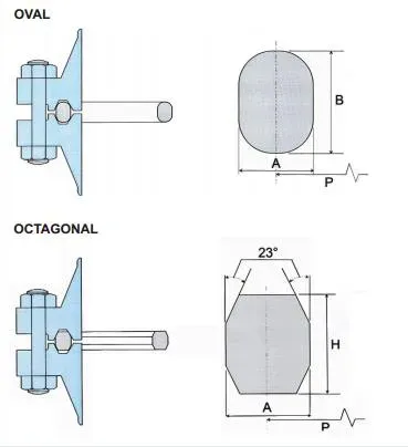
Metal ring gasket types compared:
| Ring Type | Cross-Section | Groove Compatibility | Key Feature |
|---|---|---|---|
| R (oval) | Oval | R-groove (flat bottom) | Line contact with groove walls |
| R (octagonal) | Octagonal | R-groove (flat bottom) | Face contact, stronger seal than oval |
| RX | Modified octagonal | RX-groove (special profile) | Self-energizing under internal pressure |
| BX | Square with vent hole | BX-groove (special profile) | Highest pressure; API 6A wellhead standard |
R-type oval and octagonal rings are interchangeable in the same groove, but octagonal rings provide a superior seal. RX and BX rings are not interchangeable with R-type grooves and require their own specific groove profiles.
Lap Joint Flange Face
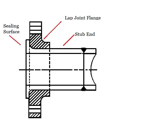
A two-piece assembly consisting of a lap joint flange and a stub end welded to the pipe. The flange rotates freely around the stub end for easy bolt hole alignment. The stub end provides the sealing surface, while the flange provides the bolting structure.
| Advantage | Description |
|---|---|
| Bolt alignment | Flange rotates freely to align bolt holes |
| Easy maintenance | Flange detaches without cutting pipe |
| Cost savings | Flange can be lower-grade material than stub end |
| Exotic alloy economy | Use Inconel/Hastelloy stub end + carbon steel flange |
Best for: Frequent dismantling, exotic alloy systems (the expensive corrosion-resistant material is only needed on the stub end), and lined pipe systems. The sealing face type follows the stub end face (typically RF).
Tongue and Groove Flange (T&G)
One flange has a tongue (raised ring); the mating flange has a matching groove. The interlocking geometry confines the gasket, preventing blowout under pressure. The confined design also provides automatic alignment of the mating flanges.
T&G flanges are specified per ASME B16.5 in two configurations: large T&G (covers a wider area for larger gaskets) and small T&G (narrower, for higher seating stress). Surface finish within the groove and on the tongue is 63 AARH max (1.6 um Ra).
| Feature | T&G Benefit |
|---|---|
| Gasket protection | Groove prevents extrusion and blowout |
| Alignment | Self-aligning, self-centering design |
| Applications | Chemical plants, high-integrity joints, moderate P/T |
| Limitation | Each flange must be paired (tongue mates with groove only) |
Male and Female Flange (M&F)
Similar in concept to T&G but with different geometry: the male flange has a 1/4” high protrusion; the female flange has a matching 3/16” deep recess. The female face retains the gasket, providing confinement against blowout. Like T&G, each flange must be paired with its counterpart.
M&F flanges offer slightly less confinement than T&G because the gasket extends to the outer diameter of the male face rather than being fully captured in a groove. They are used for moderate-pressure services where alignment is important.
Face Type Selection Guide
Choosing the correct flange face depends on pressure class, fluid service, flange material, and the connected equipment.
Selection by Pressure Class
| Pressure Class | Standard Face | Typical Gasket | Notes |
|---|---|---|---|
| Class 125 (cast iron) | FF | Full-face rubber | ASME B16.1; never use RF |
| Class 150 | RF (default) | Spiral wound (CGI) | FF available for cast iron mating |
| Class 300 | RF (default) | Spiral wound (CGI) | |
| Class 600 | RF or RTJ | Spiral wound or metal ring | RTJ standard for oil & gas |
| Class 900 | RF or RTJ | Spiral wound or metal ring | RTJ preferred for critical service |
| Class 1500 | RTJ (typical) | Metal ring (R, RX) | RF available but less common |
| Class 2500 | RTJ (typical) | Metal ring (R, BX) | RTJ strongly preferred |
| API 6A (wellhead) | RTJ (mandatory) | BX or RX ring | No RF option for wellhead flanges |
Selection by Service Conditions
Use RF when:
- General hydrocarbon, chemical, or utility service
- Moderate temperatures (below 800 deg F / 427 deg C)
- Standard process plant piping (refineries, chemical plants, power)
- Cost optimization is a priority
Use RTJ when:
- High-pressure service (Class 600 and above)
- High-temperature service (above 800 deg F / 427 deg C)
- Hydrogen, lethal, or flammable service requiring zero leakage
- Subsea pipelines, wellheads, and upstream oil & gas
- Cyclic pressure or thermal cycling
Use FF when:
- Connecting to cast iron, ductile iron, or FRP equipment
- Low-pressure utility services (water, air, HVAC)
- Non-metallic piping systems
Use T&G or M&F when:
- Gasket blowout risk is high (vacuum service, pulsating flow)
- Precise flange alignment is critical
- Specialty applications per engineering specification
Flange Face Finish
What Is Face Finish?
Face finish is the surface roughness of the gasket contact area, measured in microinches (AARH) or micrometers (Ra). It determines how effectively the gasket conforms to the flange face and creates a leak-free seal. The finish applies to all face types: RF, FF, RTJ groove, T&G, and M&F.
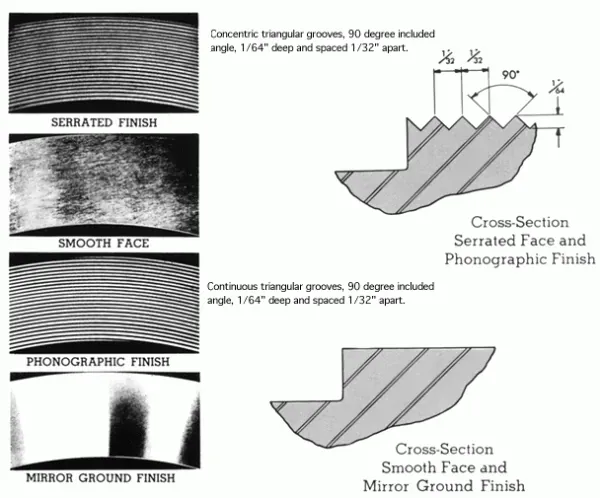
A properly finished flange face has concentric serrated grooves that create a labyrinth effect: the gasket material fills the grooves under bolt load, forcing any leak path through a tortuous, multi-ring barrier.
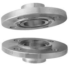
 Flange face with concentric serrated grooves (Source: Officine Orsi)
Surface Finish Requirements by Face Type
| Face Type | AARH (microinches) | Ra (um) | Groove Pattern | Standard |
|---|---|---|---|---|
| RF (Raised Face) | 125-250 | 3.2-6.3 | Concentric serrated | ASME B16.5 |
| FF (Flat Face) | 125-250 | 3.2-6.3 | Concentric serrated | ASME B16.5 |
| RTJ groove | 63 max | 1.6 max | Smooth machined | ASME B16.5 |
| T&G (Tongue & Groove) | 63 max | 1.6 max | Smooth machined | ASME B16.5 |
| M&F (Male & Female) | 63-125 | 1.6-3.2 | Smooth to light serrated | ASME B16.5 |
| Lap Joint (stub end face) | 125-250 | 3.2-6.3 | Per stub end finish | MSS SP-6 |
Gasket Compatibility by Face Finish
The gasket type dictates the required surface roughness. Using the wrong finish for a given gasket is a leading cause of flange leakage.
| Gasket Type | Required AARH | Ra (um) | Face Type | Sealing Mechanism |
|---|---|---|---|---|
| Spiral wound (graphite filler) | 125-250 | 3.2-6.3 | RF | Filler conforms to serrations |
| Spiral wound (PTFE filler) | 125-250 | 3.2-6.3 | RF | Filler conforms to serrations |
| CNAF (compressed fiber) | 125-250 | 3.2-6.3 | RF/FF | Soft material fills grooves |
| Flexible graphite (Grafoil) | 63-125 | 1.6-3.2 | RF | Thin sheet requires smoother face |
| Solid PTFE | 63-125 | 1.6-3.2 | RF/FF | PTFE cold flows; needs smoother face |
| Elastomeric (rubber) | 250—500 | 6.3—12.5 | FF | Soft rubber fills deep grooves |
| RTJ ring (oval/octagonal) | 63 max | 1.6 max | RTJ groove | Metal-to-metal deformation |
| RX / BX ring | 63 max | 1.6 max | RTJ groove | Metal-to-metal, pressure-energized |
| Kammprofile | 63-125 | 1.6-3.2 | RF | Soft facing seals against flange |
| Double-jacketed | 125-250 | 3.2-6.3 | RF | Metallic jacket with soft filler |
Types of Face Finish
| Finish | Roughness (Ra) | Tool / Method | Gasket Compatibility |
|---|---|---|---|
| Stock | 125—500 uin | Round-nose tool, 1.6mm radius | General purpose, most gaskets |
| Spiral Serrated | 125-250 uin | 90-degree V-tool, spiral pattern | Spiral wound gaskets |
| Concentric Serrated | 125-250 uin | V-tool, concentric rings | Multiple gasket types (ASME standard) |
| Smooth | 125 uin or less | Fine round-nose tool | Soft gaskets (PTFE, rubber) |
| Cold Water | 85—100 uin | Precision machining | Metal-to-metal (no gasket) |
| RTJ Groove | 63 max | Precision boring | Metal ring gaskets only |
Stock Finish
The standard, cost-effective finish suitable for most applications. Machined with a 1.6mm radius round-nose tool creating a phonographic spiral groove.
| Specification | Value |
|---|---|
| Roughness (Ra) | 125—500 uin |
| Tool | Round-nose, 1.6mm radius |
| Depth | 0.15mm |
| Feed rate | 0.8mm per revolution |
| Compatible gaskets | Non-metallic, semi-metallic, spiral wound |
The slight roughness traps gasket material and prevents lateral movement under bolt load.
Spiral Serrated
V-shaped grooves in a spiral pattern from center to periphery. Enhances mechanical engagement with soft gaskets.
| Specification | Value |
|---|---|
| Roughness (Ra) | 125-250 uin |
| Tool | 90-degree (creates 45 deg V-groove) |
| Groove density | 30—55 grooves per inch |
| Best for | Soft gaskets, thermal cycling applications |
Concentric Serrated
Same V-groove profile as spiral serrated but with concentric (target-like) rings instead of spirals. This is the ASME B16.5 standard pattern and provides multiple independent sealing paths.
| Specification | Value |
|---|---|
| Feed rate | 0.039mm per revolution |
| Depth | 0.079mm |
| Grooves | 30—55 per inch |
| Advantages | Multiple sealing paths, better gasket retention |
Smooth Finish
Very low roughness (125 uin Ra or less) with no visible tool marks. Achieved with 0.8mm radius round-nose tool at 0.3mm feed rate, 0.05mm depth.
| Application | Gasket Type |
|---|---|
| Low-pressure systems | Soft gaskets (rubber, PTFE) |
| Food/pharmaceutical | Non-contaminating materials |
| Corrosive fluids | Inert gaskets |
Cold Water Finish
The smoothest finish (85—100 uin Ra), appears shiny. Used for metal-to-metal seals without gaskets in specialized low-pressure applications.
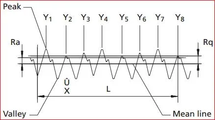
AARH (Arithmetic Average Roughness Height)
AARH (Ra) measures surface roughness as the arithmetic average height of all deviations from the mean line. Higher Ra values mean a rougher surface. It is the standard measurement unit referenced in ASME B16.5 and MSS SP-6.
ASME/ANSI Serration Requirements
| Parameter | Specification |
|---|---|
| Serrated finish Ra | 125-250 uin (3.2-6.3 um) |
| Groove shape | Concentric circles (preferred) or phonographic spiral |
| Groove pitch | 45 grooves per inch (1.8 grooves/mm) |
| Groove depth | 1/64 in. (0.4mm) nominal |
| Tool radius | 0.06” (1.5mm) or greater |
Measurement Methods
Profilometer (contact): A diamond-tipped stylus traces across the flange face perpendicular to the serration grooves. Take at least four readings at 90-degree intervals and average them for a representative result.
Optical/laser profilometer (non-contact): Uses light reflection to map the surface profile. Faster and does not risk scratching the face, but more expensive.
Surface comparator: A quick field check using calibrated reference plates. Not as precise as a profilometer but useful for initial screening.
Common Mistakes
Flange face errors account for a significant share of flanged joint failures. The following mistakes are the ones most frequently encountered during fabrication, procurement, and field assembly.
1. Mating RF Flanges to FF Flanges
The raised face acts as a fulcrum, concentrating bending stress on the FF flange. With brittle materials (cast iron, FRP), this causes cracking. With ductile materials, it causes uneven gasket loading and leakage. Solution: machine off the raised face or replace one flange to match the other.
2. Wrong Gasket for Face Type
Using a spiral wound gasket on an RTJ groove, or a metal ring on an RF face. The gasket must match the face geometry. Spiral wound gaskets need the flat raised face and concentric serrations; RTJ rings need the precision groove.
3. Incorrect Surface Finish
Installing a spiral wound gasket on a mirror-polished flange (below 125 AARH). The gasket cannot grip the surface and may blow out under pressure. Conversely, using a thin flexible graphite gasket on a rough stock finish (above 250 AARH) causes the sheet to tear on the peaks.
4. Reusing RTJ Ring Gaskets
Metal rings deform plastically during initial bolt-up. A used ring has a permanent set and will not make full contact with the groove surfaces on reassembly. Always install a new ring at every joint opening.
5. Ignoring Flange Face Damage
Radial scratches, corrosion pitting, and embedded gasket fragments from previous service create direct leak paths. A single radial scratch across the serrations defeats the labyrinth seal. Solution: inspect with a profilometer before assembly; re-machine or replace damaged flanges.
Standards Reference
The following standards govern flange face types, dimensions, finish requirements, and gasket specifications.
| Standard | Scope |
|---|---|
| ASME B16.5 | Steel pipe flanges (NPS 1/2—24): face types, dimensions, finish, RTJ groove profiles |
| ASME B16.47 | Large-diameter flanges (NPS 26—60), Series A and B: face types and finish |
| ASME B16.1 | Cast iron flanges: FF face standard for Class 125 and 250 |
| ASME B16.20 | Metallic gaskets (spiral wound, ring joint): dimensions and materials |
| ASME B16.21 | Non-metallic flat gaskets: dimensions for FF and RF flanges |
| MSS SP-6 | Standard finishes for pipe flanges and connecting-end flanges of valves and fittings |
| API 6A | Wellhead and christmas tree equipment: mandatory RTJ facing, BX/RX ring requirements |
| ASME B31.3 | Process piping code: prohibits mating different face types |
| ASME PCC-1 | Guidelines for pressure boundary bolted flange joint assembly |
Frequently Asked Questions
What is the difference between RF and RTJ flange faces?
RF (Raised Face) flanges have a raised sealing surface that uses soft or semi-metallic gaskets (spiral wound, CNAF, PTFE). RTJ (Ring Type Joint) flanges have a precision-machined groove that accepts a metal ring gasket which deforms under bolt load. RF is the ASME B16.5 default for Class 150-2500; RTJ is specified for high-pressure and high-temperature services, typically Class 600 and above. The key difference is the sealing mechanism: RF relies on gasket compression against a flat raised surface, while RTJ uses plastic deformation of a metal ring into a groove for a superior metal-to-metal seal.
Can you bolt an RF flange to an FF flange?
No. Per ASME B31.3, different face types shall never be mated. The raised face acts as a fulcrum on the flat face flange, concentrating bending stress and causing uneven gasket loading. This is especially dangerous with brittle materials like cast iron, which can crack under the concentrated load. To connect an RF pipe to FF equipment, either machine off the raised face to create a flat surface, replace one flange to match the other, or (for Class 150 only) use a full-face gasket that extends to the bolt holes to distribute the load evenly across both faces.
What is the required surface finish (AARH) for RF flanges?
ASME B16.5 specifies a serrated concentric finish of 125-250 AARH (3.2-6.3 micrometers Ra) for raised face and flat face flanges. This roughness range provides the optimal balance: rough enough for the gasket material to mechanically interlock with the grooves and resist blowout, yet smooth enough for the gasket to fully seat and create a continuous seal. The groove pitch is approximately 45 grooves per inch with a depth of 1/64 inch. RTJ grooves require a much finer finish of 63 AARH maximum.
Why should RTJ ring gaskets never be reused?
RTJ ring gaskets seal by plastically deforming into the machined groove under bolt load. Once compressed, the ring takes a permanent set and cannot return to its original shape. A reused ring will not make full contact with the groove surfaces because its profile no longer matches the groove geometry, creating leak paths. Always install a new ring gasket each time an RTJ joint is opened. Keep spare rings on site for every RTJ connection, matched by ring number (e.g., R-24 for NPS 2 Class 600) per ASME B16.20.
Which flange face type should I use for cast iron equipment?
Always use Flat Face (FF) flanges with full-face gaskets for cast iron equipment. Cast iron is a brittle material that cannot withstand the concentrated bending moment created by a raised face. Using an RF flange against a cast iron FF flange risks cracking the casting, potentially causing a catastrophic failure. If connecting steel pipe (which ships with RF as the default) to cast iron, machine the raised face off the steel flange or specify FF flanges on the purchase order. Use full-face elastomeric gaskets per ASME B16.21.
Leave a Comment
Have a question or feedback? Send us a message.
Previous Comments
I've been absent for some time, but now I remember why I used to love this site. Thank you, I'll try and check back more often. How frequently you update your website?
Very often! thank you for your interest!
My brother suggested I might like this blog. He was entirely right. This post actually made my day. You can not imagine just how much time I had spent for this information! Thanks!
Simply want to say your article is as astonishing. The clarity to your submit is just great and that i can think you’re a professional in this subject. Fine together with your permission allow me to grasp your feed to stay up to date with approaching post. Thank you 1,000,000 and please carry on the rewarding work.
I am 4 years working oil and gas industry But in this website very useful for improving my knowledge.