Valve Parts & Trim Components
Valve Key Components
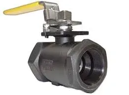
Body
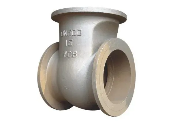 The valve body is the primary pressure-containing component. It holds the entire assembly together, forms the flow path, and takes the full brunt of line pressure, temperature, and whatever fluid runs through it. In oil and gas service, that means high pressures, corrosive hydrocarbons, and temperature extremes from cryogenic to superheated steam.
The body holds the moving components in contact with the fluid and must withstand the full operating pressure of the piping system.
Valve bodies in oil and gas service are typically constructed from carbon steel, stainless steel, alloy steels, and sometimes special alloys like Inconel, Monel, and Hastelloy.
The choice of material depends on what the valve will handle: fluid type (oil, gas, water, etc.), temperature, pressure, and corrosion potential. Stainless steel and nickel alloys are preferred where corrosion resistance is the primary concern.
The body can be manufactured by casting or forging steel in a variety of shapes, designs, and grades.
In the oil and gas industry, the most common materials for cast bodies are ASTM A216 and ASTM A105 for forged bodies (high-temperature service). For low-temperature service, ASTM A352 LCB/LCB and ASTM A350 LF2/LF3 are used, respectively, for cast and forged bodies.
As the temperature, the pressure, or the corrosion increase, stainless steel bodies become necessary: ASTM A351 CF8 (SS304) and CF8M (SS316) for cast devices, and the various ASTM A182 Fxx (F304, F316, F321, F347) for forged types.
For specific applications, special material grades with even stronger corrosion resistance are used, such as super austenitic stainless steels (SMO 254), duplex and super duplex steels (F44, F51, F53, F55), and nickel alloys (Inconel, Incoloy, Hastelloy).
For marine applications, non-ferrous materials or alloys are the standard choices: Monel, Cupronickel, Aluminum-bronze alloys, and other alloys combining Nickel, Copper, and Aluminium. Cast iron bodies, the cheapest option, are limited to water distribution and other low-pressure applications.
The valve body design covers three main areas:
- Connections: Valve bodies have various end connections for integration into piping systems. These can be flanged, threaded, welded, or socket welded, each suited to different applications and pressure ratings.
- Pressure Containment: The body must contain the operating pressure without leakage. Wall thickness and material composition are calculated for the maximum expected pressure and thermal expansion.
- Flow Path: The internal flow path can be straight-through or angular, and it determines flow direction and characteristics. The cavity and port geometry is shaped to minimize flow resistance while maintaining operational efficiency.
The valve body houses the following internal components:
- Trim: The internal parts in direct contact with the fluid (disc, seat, and stem). The trim regulates flow and sealing within the valve.
- Bonnet: The component that attaches to the valve body and encloses the internals. It can be bolted, screwed, or welded to the body.
- Packing: A sealing system within the valve body that prevents fluid leakage around the stem.
In oil and gas operations, system reliability and safety depend directly on valve quality. Valve bodies must meet stringent industry standards and certifications from API (American Petroleum Institute) and ASME (American Society of Mechanical Engineers) to handle the demanding operating conditions. They control flow, pressure, and direction of petroleum products, natural gas, and by-products across exploration, production, refining, and distribution.
Body End Connections
Valves can be connected to other mechanical devices and pipes in different ways. The main end types are flanged and buttweld (for devices above 2 inches) and socket weld or threaded/screwed (NPT or BSP) for small-diameter devices. Butterfly valves have more articulated body-end types, like lug, wafer, and double-flanged ends.
Let’s now examine the different types of valve bodies’s end types:
Flanged Ends
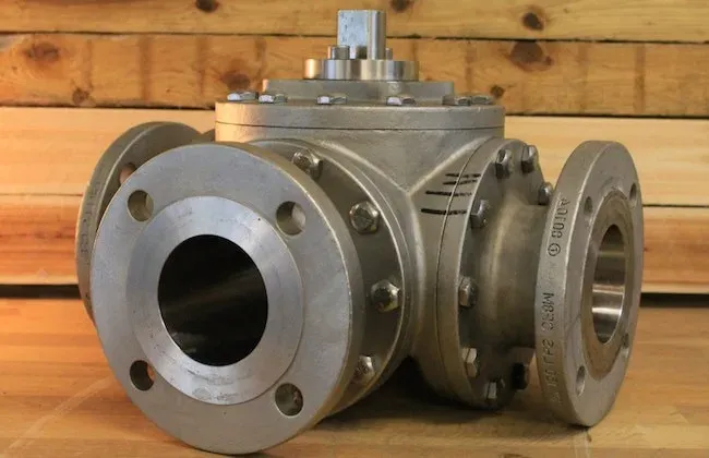
In this case, the device has two flanged ends that can be connected with a pipe by using a mating (companion) flange.
A flanged connection requires a proper number of stud bolts and nuts, as indicated by the ASME B16.5 specification, and a suitable gasket.
Flanged connections are common for larger-diameter valves, and they produce long-lasting, strong joints.
The flange face may be raised, flat, ring joint, tongue, and groove male & female (the most common finish is the RF type, i.e. raised face), and be finished in any of the available variants (stock, serrated or smooth).
Socket Weld and Buttweld
 Socket weld valve end connections
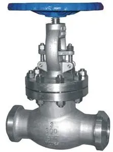 Buttweld valve end connections
Valves with socket weld ASME B16.11 or buttweld ends ASME B16.25 are welded to the connecting pipe.
Buttweld valve end connections
Valves with socket weld ASME B16.11 or buttweld ends ASME B16.25 are welded to the connecting pipe.
Welded connections are more expensive to execute than flanged joints, as they require more work, but are more reliable and less prone to leakages in the long run.
Socket weld and buttweld ends are used for high-pressure pipelines (socket weld for smaller sizes, below 2 inches, and buttweld for larger diameters).
Buttweld connections require full welding of the beveled ends of the two parts to be joined, whereas socket weld connections are made by fillet welds.
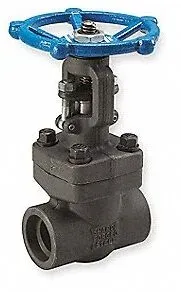
Threaded End Connections
In this case, the device is connected to the pipe by a thread (tapered thread), which may be BSP or NPT (more common in the petrochemical industry).
This type of connection is used for low-pressure pipelines with bore sizes below 2 inches, not subject to mechanical forces such as vibration and elongation.
Threaded connections are quicker to execute and cheaper, as the pipe is simply screwed onto the valve, without the need for flanges, stud bolts, or welding operations.
In case of leakage, however, threaded connections need to be changed and can’t be repaired (which is instead possible for the two previous types of pipe-to-end connections).
BSP VS. NPT Threaded Connections
BSP (British Standard Pipe) and NPT (National Pipe Thread) are the two most widely used threaded connection standards for pipes and fittings. Both create secure threaded joints for fluid transport, but they differ substantially in geometry, sealing method, and regional adoption.
Getting the distinction right matters: cross-threading an NPT fitting into a BSP port damages the threads, leaks, and wastes the fitting.
Design Differences between BSP and NPT Threaded-Ends
- Thread Form: NPT threads have a 60-degree thread angle with a tapered profile, meaning the thread diameter changes along the length of the fitting. This taper creates a seal through wedging action, typically requiring thread sealant or tape for a leak-free joint. BSP threads come in two variants: BSP Parallel (BSPP) with a straight profile, and BSP Tapered (BSPT) with a taper similar to NPT but at a 55-degree thread angle. The different angles affect how each thread type seals and mates.
- Sealing Mechanism: NPT fittings rely on interference fit between male and female threads, requiring sealant. BSPP connections typically need a bonded seal or washer between the male and female ends, while BSPT connections seal on the thread itself like NPT, but the thread profiles are not interchangeable.
Application and Compatibility
- Geographical Use: NPT is the standard in the United States and Canada for pneumatic, hydraulic, and plumbing connections. BSP threads are prevalent in Europe, Asia, Australia, and most other regions. Both exist worldwide, but local preference shapes availability and standard compliance.
- Interchangeability: NPT and BSP fittings are not interchangeable. The thread angles and pitch differ, so forcing one into the other damages threads and creates leaks. Adapters are required to connect NPT and BSP components safely.
Choosing Between BSP and NPT
Selecting between BSP and NPT comes down to a few practical factors:
- Regional Standards and Availability: Use whichever thread type matches local standards and is readily available for compatibility with existing systems and easy replacement.
- Application Requirements: Consider the fluid type, pressure, and seal requirements. BSPP works well where a flat sealing surface is needed, while NPT and BSPT produce tighter seals in higher-pressure systems.
- System Design: Existing piping and equipment typically dictate the thread standard. Mixing standards means adapters and additional leak paths; avoid it when possible.
Knowing the differences between BSP and NPT helps engineers and technicians avoid costly mistakes during assembly. Correct selection and installation keep the system leak-free and compliant with regional codes.
Valve Bonnet
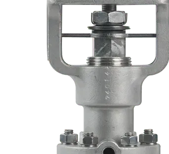 The valve bonnet is the second most important pressure-containing component after the body. It covers the valve body, encloses the internals (stem, disc, and seat), and together with the body forms the complete pressure boundary. Here is a closer look at its functions, types, and why it matters:
Functions of the Valve Bonnet
- Pressure Containment: The bonnet seals the top of the valve body and must withstand the full operating pressure. A bonnet failure is a pressure-boundary failure; it leaks process fluid to atmosphere.
- Component Protection: By enclosing the internal parts, the bonnet shields them from external contaminants and physical damage, which directly affects valve reliability and service life.
- Access Point: Most bonnet designs allow removal for maintenance, repair, or replacement of internal components. This is a practical advantage during turnarounds and unplanned maintenance.
Types of Valve Bonnets
Valve bonnets come in different designs, each matched to specific pressure, temperature, and maintenance requirements:
| Bonnet Type | Description |
|---|---|
| Bolted Bonnet | A widely used design where the bonnet is attached to the valve body with bolts or studs and nuts. It provides a sturdy seal and is suitable for various pressures and temperatures. |
| Screwed Bonnet | In this design, the bonnet is screwed directly into the valve body. Screwed bonnets are commonly used in smaller valves and lower-pressure applications. |
| Welded Bonnet | For valves used in high-pressure and high-temperature applications, a welded bonnet provides a leak-proof seal by permanently welding the bonnet to the valve body. This design is often used when the valve does not require regular maintenance. |
| Pressure Seal Bonnet | Used in high-pressure applications, this design employs a gasket that is pressure-energized to enhance the seal between the bonnet and the valve body as the internal pressure increases. |
| Union Bonnet | A design that allows for easy disassembly and reassembly of the valve for maintenance. The bonnet and body are connected with a threaded union, facilitating straightforward access to the valve internals. |
Significance of the Valve Bonnet
The bonnet’s design and construction directly determine whether the valve holds pressure under operating conditions. Selecting the right bonnet type (based on pressure, temperature, and how often the valve needs to be opened for maintenance) is a fundamental engineering decision that affects both performance and service life.
In short, the bonnet completes the pressure envelope, protects the internals, and (depending on type) provides the access point for maintenance and repair. Its role in system safety and valve integrity is central.
Trim
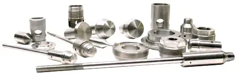 The trim is a collective name for all the internal parts of the valve that can be removed and replaced (these parts are also called “wet”, as they are in direct contact with the conveyed fluid).
Typically, the trim includes components such as the disc, the seat, the stem, the glands, the bushings, and the sleeves needed to guide the stem (the actual list of components that make up the trim depends, actually, on the type of device).
The trim determines how the valve operates: how it opens, closes, throttles, and seals. It directly controls flow, pressure, and temperature regulation within the system. Understanding trim components and their functions is necessary for selecting the right valve and maintaining it over its full service life.
Components of Valve Trim
The main components of valve trim include:
- Disc or Ball: The part that physically blocks or opens the flow path. In globe and gate valves, this is a disc; in ball valves, it is a ball with a bore through the center.
- Seat: The seat provides the sealing surface against which the disc or ball closes. Seat quality and material determine how tight the shutoff is and whether the valve leaks.
- Stem: The stem connects the actuator or handwheel to the disc or ball and transmits the force needed to move it. It can travel linearly (gate and globe valves) or rotate (ball and butterfly valves).
- Cage: In some valve designs, particularly globe valves, the cage surrounds the disc, guides its travel, and provides additional flow control and stability.
- Spring: Springs appear in some trim assemblies, notably in check valves and safety valves, where they supply the closing or opening force under specific conditions.
- Plug: In plug and some globe valve designs, a plug serves as the obstructing element rather than a disc or ball.
Importance of Valve Trim
- Flow Control: Trim design and material directly affect the valve’s ability to control flow rate, direction, and pressure drop. Different trim configurations serve different control needs, from simple on/off to precise modulation.
- Durability and Wear Resistance: Trim components take continuous punishment from the process fluid. Selecting trim materials that are compatible with the fluid, temperature, and pressure is what determines whether the valve lasts five years or fifteen.
- Maintenance and Replacement: Trim components wear out and need periodic replacement. Modular trim designs simplify this work: you pull the trim, swap the worn parts, and reinstall rather than replacing the entire valve.
Selecting the Right Valve Trim
Choosing the right trim requires matching it to the fluid (corrosiveness, viscosity, solids content), the required flow control characteristics, and the operating conditions (pressure and temperature). The right combination of trim material and design keeps the valve performing efficiently over its intended life, reduces maintenance intervals, and minimizes unplanned shutdowns.
Typical trim combinations for gate, globe, and check valves have been standardized by the API trim chart.
The valve trim is the heart of valve performance: It includes all internal parts in contact with the fluid (disc, seat, stem, glands, bushings). Trim material selection directly determines flow control capability, wear resistance, and maintenance frequency. Always match trim materials to the process fluid and operating conditions.
In practice, valve trim is the collective term for the internal components that interact with the process fluid. Its design and material composition govern how well the valve controls flow, how long it lasts, and how much maintenance it needs.
Disc
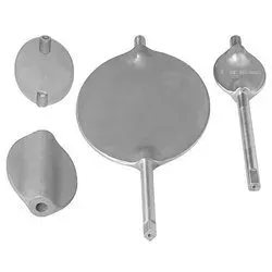
The valve disc is the component within the trim that does the actual work of opening, closing, or throttling flow. It sits directly in the flow path, and its movement toward or away from the valve seat controls how much fluid passes through.
The disc’s design, material, and condition determine how well the valve seals, how precisely it regulates flow, and how long it lasts, whether in a simple water line or a high-pressure chemical reactor.
Functionality of the Valve Disc
- Flow Regulation: The disc’s primary job is to control flow through the valve. By moving closer to or further from the seat, the disc changes the opening size, and thus the flow rate.
- Sealing: When fully seated, the disc provides a tight shutoff that stops all flow. The quality of this seal directly determines whether the valve leaks. A disc that doesn’t seat properly is a disc that leaks.
- Modulation: In globe and control valves, the disc can be positioned at intermediate points to control flow rate precisely. This fine throttling capability is critical in process applications where maintaining specific flow parameters matters.
Types of Valve Discs
Disc design varies by valve type and application:
| Disc Type | Description |
|---|---|
| Flat Discs | Used in gate valves, flat discs move vertically to the flow direction, providing an on/off function by either completely blocking or allowing flow. |
| Ball Discs | In ball valves, the disc is a sphere with a hole through its center. Rotation of the ball opens or closes the flow path, offering both shutoff and throttling capabilities. |
| Plug Discs | Utilized in plug valves, these discs are cylindrical or conically tapered plugs that rotate to control flow through an opening in the plug. |
| Butterfly Discs | Butterfly valves use a flat, circular disc that pivots in the center of the valve body. This design allows for quick operation and is used for both isolation and flow regulation. |
Material Considerations
Disc material selection depends on the fluid characteristics (corrosiveness, temperature, pressure), the valve’s service, and the expected life. Common materials include:
- Metals: Stainless steel, carbon steel, brass, and bronze are widely used for their strength, durability, and resistance to high temperatures and pressures.
- Plastics: For corrosive-fluid applications or lower-pressure/lower-temperature conditions, plastics such as PVC, PTFE (Teflon), and PVDF offer strong corrosion resistance at lower cost.
- Ceramics: Where the fluid carries abrasive particles, ceramic discs provide superior wear resistance.
Significance of the disc for valves’s performance
The disc is the working heart of the valve: it controls flow, provides shutoff, and enables throttling. Its design, material, and fit against the seat determine how the valve performs in service. Selecting the right disc requires understanding the application: what the fluid is, what conditions the valve operates under, and what level of control is needed.
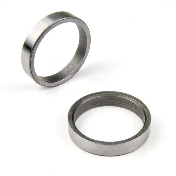
Seats
 Valve seats are the internal surfaces that mate with the disc (or plug, ball, etc.) to form the seal that stops or controls flow. When a valve is closed, the disc-to-seat interface is the last line of defense against leakage. The seat’s material, surface finish, and condition directly determine whether the valve seals tight or weeps.
Function and Importance
- Sealing Surface: The seat’s primary function is to provide a smooth, precise contact surface for the disc. When the disc is fully closed against the seat, the result is a seal that prevents fluid from passing through.
- Flow Regulation: In throttling valves, the seat works with the disc to modulate flow. Seat geometry influences flow characteristics and control precision.
- Durability and Wear Resistance: Seats take repeated contact from the disc and continuous exposure to the process fluid, pressure cycles, and mechanical operation. They must resist wear and deformation over thousands of cycles.
Seats Materials
Valve seats are made from a range of materials, selected based on fluid type, operating pressure, temperature, and corrosion exposure:
- Metals: Stainless steel, bronze, and brass are common for their durability and high-temperature/high-pressure resistance. Hardened metals or alloys are specified for severe service where wear is the dominant failure mode.
- Soft Seats: PTFE (Teflon), nylon, and other elastomers deliver excellent sealing and chemical resistance. Soft seats work well where metal-to-metal contact cannot achieve an adequate seal, but they are limited to lower temperature and pressure ranges.
- Ceramics: For high-wear or corrosive service, ceramic seats offer superior hardness, wear resistance, and thermal stability.
Design Considerations
Seat design has a direct impact on function and service life:
- Seat Shape and Angle: The contour and angle of the seat affect sealing efficiency and flow characteristics. Seats can be profiled for linear or equal percentage flow characteristics in control valve applications.
- Interchangeability: Some valve designs feature replaceable seat rings that can be swapped when worn or damaged, extending valve life without replacing the entire assembly.
- Sealing Method: The seat-to-disc contact area and sealing method (metal-to-metal vs. soft seal) determine seal tightness and which applications the valve can handle.
Special treatments for valve seats
Valve seats take the hardest beating of any valve component; they must seal reliably despite repeated mechanical contact, corrosion from the process fluid, and erosion from particulates. To extend their life and sealing capability, valve seats may undergo various special treatments. The treatment chosen depends on the operating conditions:
Hardening Treatments
- Surface Hardening: Induction hardening and flame hardening increase surface hardness and wear resistance without sacrificing the toughness of the base material.
- Case Hardening: Carburizing, nitriding, and carbonitriding add a hard, wear-resistant surface layer while maintaining a ductile core. These treatments are especially valuable when the valve handles abrasive particles.
Coating Treatments
- Stellite Overlay: Stellite, a cobalt-chromium alloy, provides outstanding hardness along with wear and corrosion resistance. A Stellite overlay on valve seats significantly extends service life in high-pressure, high-temperature, and erosive conditions.
- Chrome Plating: Chromium plating offers good wear resistance and low friction, valuable where minimizing leakage is the top priority.
- Nickel Alloy Coatings: Nickel-based coatings, including Inconel and Monel, provide enhanced corrosion resistance in aggressive chemical environments.
- Thermal Spray Coatings: Techniques like High-Velocity Oxygen Fuel (HVOF) spraying apply tungsten carbide or other hard materials to the seat surface, improving both wear and corrosion resistance.
Material Upgrades
- Solid Seats: In extreme conditions of temperature, pressure, or corrosion, the entire seat may be manufactured from a high-performance material such as ceramics or high-nickel alloys.
- Inserts: Durable inserts made from ceramics or hardened metals can be pressed or screwed into the valve body, providing superior wear and corrosion resistance at the sealing surface.
Lapping and Grinding
- Precision Lapping: Rubbing the seat against a flat surface with an abrasive compound produces a high-quality surface finish and flatness. Lapping produces the tight seat-to-disc contact needed for a reliable seal.
- Grinding: Grinding can restore damaged or worn seats, bringing the sealing surface back to serviceable condition and extending the valve’s operational life.
Each treatment has its place and is chosen based on the valve’s service, fluid properties, and operating conditions (pressure, temperature, and abrasive particle content). Correct treatment selection reduces maintenance costs and extends valve life across industrial and commercial applications.
Importance of valve seats
Valve seats are the primary sealing interface: they regulate fluid flow and prevent leakage when the valve is closed. Seat material and design must match the valve’s service conditions: fluid compatibility, pressure, temperature, and control requirements. Routine inspection and timely seat replacement keep the valve performing to specification and protect overall system integrity.
Stem
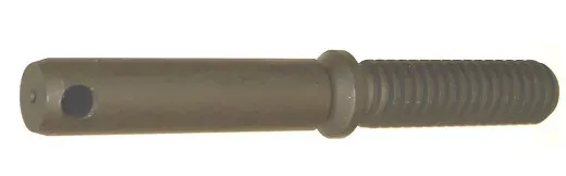
The stem of a valve is used to open/close the fluid as it moves the disc. The stem is linked to the valve actuator or to the manual handwheel (or lever), at one end, and is connected to the valve disc on the other end. For the gate and globe types, the stem operates a linear motion on the disc, whereas, for the ball, butterfly, and plug types, the disc rotates to open or close the device (“quarter turn valves”).
Stems are made of forged steel and are connected to the disc by threading or other means. A proper finish of the stem surface is necessary to prevent leakages.
There are five main types of stems:
| Stem Type | Description |
|---|---|
| Rotary | This is a standard type of ball, plug, and butterfly valve. A quarter-turn motion of the stem is needed to open/close the device. |
| Sliding | In this case, the stem does not execute any rotation. The stem slides in and out the valve to open or close it. This design is common in hand-operated lever rapid-opening valves. It is also used in control valves are operated by hydraulic or pneumatic cylinders. |
| Rising type with outside screw and yoke (“OS&Y”) | The external side of the stem is threaded while the part of the stem which is inside the valve is plain. The threads of the stem are isolated from the medium by the packing. Two alternative designs are available. The “OS&Y” design is common for valves above 2”. |
| Rising type with an inside screw (“IS&Y”) | The threaded part of the stem is positioned inside the valve body, whereas the stem packing lays outside. With this design, the stem threads are in touch with the medium flowing through the pipeline. Once rotated, the stem and the hand wheel rise together and open the valve. |
| Non-rising stem type with inside screw | The threaded part of the stem is inside the valve and does not rise. The valve disc floats on the stem, like a nut if the stem is rotated. Stem threads are in contact with the media of the pipeline, and as such, may be exposed to its corrosive impact. This is the reason why such a design is used when the available space to position the valve is too narrow to permit linear movement, and the media does not cause erosion, corrosion, or abrasion of the stem material. |
Packing
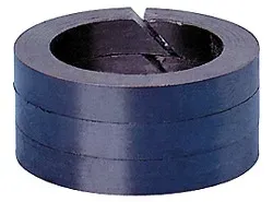
The gasket that seals the stem with the bonnet is called packing and comprises the following components:
- Gland follower, which is a sleeve that compresses the packing, by a gland into the stuffing box.
- Gland is a type of bushing, which compresses the packing into the stuffing box.
- A stuffing box is a chamber in which the packing gets compressed.
- Packing is available in different materials, like PTFE, elastomers, fibrous material, etc.
- A backseat is sitting inside the bonnet. The back seat provides a seal between the stem and bonnet and prevents system pressure from building against the valve packing once the valve is fully open. Back seats are often used in gate and globe valves.
- The valve packaging shall be properly designed and manufactured to minimize the possible damage to the stem and minimize the risk of leakages of fluids. On the other hand, it is necessary to observe that a too-tight packing may affect the stem.
Valve Actuator
Valve actuators convert control signals (or manual effort) into mechanical motion to open, close, or modulate valve position.
Choosing the right actuator depends on valve size, required operating speed, the force needed to move the valve, environmental conditions, and whether the application calls for on/off, throttling, or proportional control.
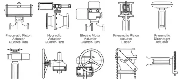
There are multiple actuator types, each with its own strengths and typical applications.
Key types of actuators
Manual Actuators
Manual actuators require human effort to operate the valve, using handwheels, levers, or gears. They are straightforward and need no external power source.
- Advantages: Simplicity, no power supply required, and direct operator control.
- Applications: Situations where automated control is unnecessary, or as a backup for operating valves during power loss.
A hand-operated or manual valve is generally equipped with a hand wheel that can be rotated clockwise or counter-clockwise to open and/or close the valve (typical for gate and globe valves). Ball, plug, or butterfly are actuated using a lever (manual quarter turn valves).In the following cases, it is not either possible nor advisable to use manual valves:
- Large dimension valves that operate at high pressures
- Valves that need to be controlled from a remote location
- Valves that require, for the nature of the process, a very fast open or close operation
In all these cases, a valve actuator is needed. The actuator produces linear and rotary motion able to open or close a valve (the actual movement depends of course on the type of the valve, linear or quarter turn).
Pneumatic Actuators
Pneumatic actuators use compressed air to generate the motion that operates the valve. They are among the most common actuator types in industrial plants because they are simple, reliable, and cost-effective.
- Advantages: Rapid response time, inherently explosion-proof, and straightforward design.
- Applications: Widely used in oil and gas, chemical, water treatment, and manufacturing plants.
Hydraulic Actuators
Hydraulic actuators use pressurized fluid, typically oil, to move the valve. They produce high force in a compact footprint, which makes them practical for large valve operations.
- Advantages: High force output, precise control, and well-suited for heavy-duty applications.
- Applications: Power generation and offshore platforms where high operating forces are the norm.
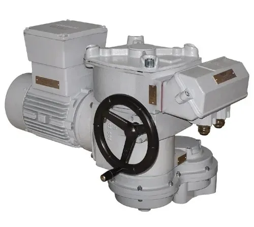
Electric Actuators
Electric actuators use an electric motor to drive the valve to the desired position. They integrate readily with electronic control systems for accurate positioning and feedback.
- Advantages: Precise control, easy integration with control systems, and well-suited for remote operation.
- Applications: HVAC, water treatment, and light industrial applications.
Electro-Hydraulic Actuators
Electro-hydraulic actuators combine electric and hydraulic technologies. An electric motor drives a hydraulic pump, which in turn moves the actuator.
- Advantages: Combines electric precision with hydraulic force, well-suited for remote and automatic control.
- Applications: Large valve operations and safety shutdown systems where both precise control and high force are needed.
Gas over-oil Actuators
A gas-over-oil actuator uses a combination of high-pressure gas and hydraulic oil to generate valve-operating force. This type is particularly common in the oil and gas industry for remote pipeline applications or locations with no electrical power.
How It Works
- Mechanism: Pressurized gas (often natural gas tapped from the pipeline itself) pushes on hydraulic fluid (oil), which moves the actuator piston. This piston movement is mechanically linked to the valve, enabling it to open, close, or modulate as required.
- Components: The actuator typically consists of a gas pressure chamber, an oil reservoir, control valves for directing gas and oil flow, and a piston or diaphragm that converts pressure into mechanical motion.
Advantages
- Remote Operation: Since they can use pipeline gas as the power source, gas-over-oil actuators work in remote locations with no electrical supply.
- Safety: They require no electricity, which eliminates ignition risk in explosive atmospheres.
- Reliability: These actuators operate in harsh environments with minimal maintenance, a significant advantage in remote pipeline stations.
Applications
- Pipeline Valves: Widely used for control and safety shutdown valves in natural gas pipelines.
- Offshore Platforms: Valve actuation on offshore gas extraction platforms, where reliability and safety are paramount.
- Isolated Installations: Any valve actuation application in remote or hard-to-access locations within the oil and gas sector.
Gas-over-oil actuators provide a dependable solution for valve automation, combining hydraulic power and precision with the safety and availability of pipeline gas as a power source. They remain a core component in modern oil and gas pipeline infrastructure.
Solenoid Actuators
Solenoid actuators use electromagnetic solenoids to operate the valve. They are typically used for on/off control in smaller valve applications.
- Advantages: Fast response time, simple design, and well-suited for small valves.
- Applications: Fluid power systems, medical equipment, and general on/off applications.
Each actuator type has distinct advantages and is selected based on the specific application: control requirements, operating environment, and valve size. Understanding the strengths and limitations of each type is central to choosing the right actuator for a given system.
Rotork and Auma actuators have the largest market shares within the petrochemical industry.
Leave a Comment
Have a question or feedback? Send us a message.
Previous Comments
WATER FLOOD STATION GATE VALVE , RF , 125-250 AARH , CS . BODY AND BONNET , 11-13 % CROMETRIM , HARD FACED SAET RING AND DISC , FLEXIBLE WEDGE , FULL PORTDESIGN BOLTED BONNET , OS &Y ., PER API 600/ASME B 16.34 & ASMEB 16.10 VALVES SHALL BE TESTED ACCORDING TO API 598 4″ 150 # CHECK VALVE ( 4″ #150 ) , RTJ , SWING TYPE , CS. BODY & CAP & DISC & SEAT & RING & HING AND HING PIN , AS PER API 6D/BS 5153 , ASTM A216 , TESTED AS PER API 598 / ASME B16.34
Thanks for pointing out that there are different packings available in different materials for the valves. I hope to find the best one for the valves of my property to ensure that we are safe once we can move into this property this year. I should seek the advice of a professional to really choose the right pieces of equipment needed related to this.
I didn't know that as the temperature increases, stainless steel becomes necessary. I might as well get the metal now. That way I don't have to change them as the temperature rises eventually.
Thanks for sharing a blog about valve parts. I especially enjoyed reading the details. Let us know if you want information about valves for an upcoming article.
Dear sir, we need urgent price for Parts# M3480-2 BONNET ,VALVE,SOLENOID (0.75 IPS/110VAC 2 WAY . QTY-6 . Please can you urgently quote us with urgent delivery time including freight charges EX-work jeddah to saudi Arabia. Kindest Regards ABDUL Sales & Marketing Manager International Maritime Trading Est. Office # 316 3rd Floor Salma Commercial Center Madina Road Jeddah – 21464 Kingdom of Saudi Arabia Tel: +966 12 6532036 Fax:+9661 2 6141265 Mobile:+966 563276478 Email: [email protected]