A ball valve features a spherical disc to open and close the flow of the fluid. Ball valves represent the industry standard for pipeline shut-off applications, as their design guarantees very tight and leak-free sealing even after years of operation. The two key types of ball valves are the floating and the trunnion designs (side or top entry). The body can be cast or forged and monolithic or split (in 2 or 3 pieces). The API 6D and ASME B16.34 are key specifications.
BALL VALVES
WHAT IS A BALL VALVE
A ball valve is a type of quarter-turn valve that controls the flow of a fluid through it with a spherical disc known as a ball. The ball has a hole, or port, through the middle so that when the port is in line with both ends of the valve, flow will occur. When the valve is closed by turning the handle 90 degrees, the ball is rotated so that the hole is perpendicular to the flow paths of the valve body, effectively blocking the flow.
Key Features
- Quarter-Turn: The valve operates with a simple 90-degree turn of a handle or lever, making it quick and easy to open or close.
- Full Port Design: Many ball valves are full port, meaning the hole in the ball is the same size as the pipeline, resulting in minimal friction loss.
- Durability: Ball valves are known for their durability and long service life, even in high-pressure applications.
- Versatility: Suitable for a wide range of applications, from water and gas to chemicals and corrosives, depending on the materials used in construction.
- Sealing Mechanism: Provides excellent sealing capabilities, with many ball valves designed to be leak-proof.
Types
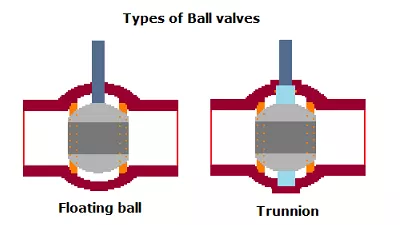
- Floating Ball Valve: The ball is held in place by the compression of two elastomeric seats against it. The ball moves slightly within the valve body to maintain contact with the downstream seat, ensuring a tight seal.
- Trunnion Mounted Ball Valve: The ball is anchored at the top and bottom, reducing the operating torque and allowing for the control of larger sizes and higher pressure services.
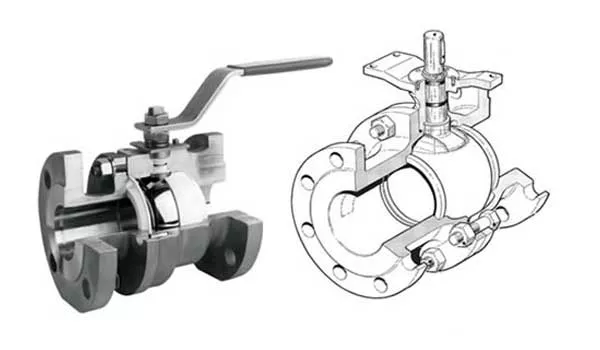
- Top Entry & Side Entry: Refers to how the ball valve is assembled, which impacts maintenance and repair ease.
Each type of ball valve is explained in greater detail below.
Applications
Ball valves are used in a variety of applications across many industries, including water supply, gas supply, oil and petrochemical processes, manufacturing, and more. Their ability to quickly shut off flow makes them particularly useful for emergency and shut-off applications. Material selection for the valve body, ball, and seals (often made from metal, plastic, or ceramic) can vary based on the fluid’s nature, ensuring compatibility and performance across a wide range of temperatures and pressures.
BALL VALVE PARTS
A ball valve consists of several key components, each playing a crucial role in its functionality. Understanding these parts can help in selecting the right valve for a specific application, as well as in maintenance and troubleshooting. Here’s an overview of the main parts of a ball valve:
1. Body
The outer casing of the valve that holds all other components together. It can be made from a variety of materials, including stainless steel, brass, plastic, and others, depending on the application requirements.
2. Ball
The core component that controls flow through the valve. It is a spherical disc with a hole (or bore) through its center. The material of the ball usually matches or complements the body material for compatibility with the fluid being handled.
Special Treatments for the Ball of a Ball Valve
The ball of a ball valve can undergo various special treatments to enhance its performance, durability, and suitability for specific applications. These treatments can improve the ball’s resistance to wear, corrosion, and galling, as well as its sealing capabilities. Here are some commonly applied special treatments for the ball of a ball valve:
1. Hard Coatings
- Chrome Plating: A thin layer of chromium is electroplated onto the ball surface, enhancing its wear and corrosion resistance. This treatment is suitable for applications involving abrasive materials or corrosive fluids.
- Nickel Plating: Similar to chrome plating, nickel plating provides corrosion resistance and increased durability, especially in environments where the valve is exposed to harsh chemicals.
- Tungsten Carbide Coating: Applied using High-Velocity Oxygen Fuel (HVOF) spraying, this coating offers exceptional hardness and resistance to extreme wear and erosion.
2. Soft Coatings
- PTFE (Polytetrafluoroethylene): A soft coating that provides excellent chemical resistance and reduces friction between the ball and seats. This is particularly beneficial in applications requiring tight sealing and low operating torque.
- Enamel Coating: Offers good corrosion resistance and is used in applications where chemical compatibility is a concern.
3. Electroless Nickel Coating
This process deposits a uniform nickel-phosphorus or nickel-boron alloy coating on the ball, offering excellent corrosion and wear resistance. It’s particularly useful in offshore and marine applications, as well as in the processing of corrosive fluids.
4. Nitriding
Nitriding enhances the surface hardness of the ball through a heat-treating process that diffuses nitrogen into the surface. This treatment improves wear resistance and fatigue strength, making it suitable for high-pressure and high-velocity applications.
5. Cryogenic Treatment
This treatment involves cooling the ball to cryogenic temperatures and then gradually warming it up. The process stabilizes the structure of the material, improving its toughness and wear resistance. It’s especially beneficial for valves used in cryogenic services.
6. Molybdenum Disulfide Coating
A dry lubricant coating that reduces friction and improves wear resistance. It’s useful in applications where lubrication is difficult or where the valve must operate under high loads or extreme temperatures.
7. Fusion Bonded Epoxy Coating
A thick, protective coating that offers excellent corrosion protection. It’s widely used in water and wastewater applications, as well as in pipelines transporting corrosive gases and liquids.
The choice of treatment depends on the specific operational conditions, including the type of fluid handled, pressure, temperature, and the presence of abrasive or corrosive elements. These specialized treatments can significantly extend the life of a ball valve and enhance its performance in demanding industrial applications.
3. Seats
Rings that provide a seal between the ball and the valve body. When the valve is closed, the ball presses against these seats to create a tight seal, preventing fluid from leaking past. Seats can be made from soft materials (like PTFE) for better sealing or hard materials for high-temperature applications.
Special Treatments for the Seats of a Ball Valve
The seats of ball valves play a crucial role in ensuring tight sealing and smooth operation across a wide range of applications, from low-pressure residential systems to high-pressure industrial processes. To enhance their performance, durability, and resistance to harsh conditions, several special treatments and material enhancements can be applied to ball valve seats. Here are some of the notable treatments and materials used:
1. Soft Seating Materials
- PTFE (Polytetrafluoroethylene): Offers excellent chemical resistance and a low friction coefficient, suitable for a broad temperature range. Variants like reinforced PTFE (RPTFE) have added fillers to improve strength and wear resistance.
- PEEK (Polyether Ether Ketone): A high-performance thermoplastic with excellent mechanical and chemical resistance properties, suitable for high-pressure and high-temperature applications.
- Nylon: Provides good wear resistance and strength, suitable for certain types of oils and hydrocarbons.
2. Metal Seating
Hard Facing: Metal seats can be coated or overlaid with harder materials such as Stellite, tungsten carbide, or chromium carbide through processes like welding or thermal spraying. These treatments improve wear resistance, thermal stability, and longevity in severe service conditions, including abrasive and corrosive environments.
3. Elastomeric and Composite Materials
- Viton, Buna-N (Nitrile): Elastomers offer good sealing capabilities and resistance to a variety of chemicals and temperatures. They are used in applications where softer sealing materials are needed for improved sealing at lower pressures.
- Composite Materials: Seats made from a combination of materials, such as fibrous reinforcements in a resin matrix, offer enhanced performance characteristics, including resistance to wear and chemical attack.
4. Surface Treatments
- Electroless Nickel Plating (ENP): A chemical process that deposits a nickel-phosphorus coating on the surface of the seat. ENP improves corrosion resistance and hardness, enhancing the seat’s durability in corrosive environments.
- Surface Coatings: Various coatings can be applied to improve resistance to chemicals, temperature, and wear. Examples include PFA (Perfluoroalkoxy) and FEP (Fluorinated Ethylene Propylene) coatings, which are types of fluoropolymers with excellent chemical resistance.
5. Seat Design Enhancements
- Live-Loaded Seats: Some ball valve seats are designed with live-loading mechanisms, such as spring energizers, to maintain consistent sealing force against the ball. This compensates for wear and thermal expansion, ensuring a reliable seal over the valve’s lifespan.
Selecting the appropriate seat material and treatment depends on several factors, including the type of fluid being handled, operating pressures and temperatures, and specific application requirements. By choosing the right seat treatment, users can significantly enhance the performance, reliability, and service life of ball valves in their systems.
4. Stem
Connects the ball to the control mechanism (like a handle or actuator) outside the valve. The stem allows for the rotation of the ball, typically a quarter turn (90 degrees) from the open to the closed position. It’s designed to prevent leakage from the valve body to the atmosphere.
5. Handle or Actuator
Used to manually or automatically control the valve’s position. A manual handle is turned to rotate the stem and the attached ball. Actuators, which can be pneumatic, electric, or hydraulic, allow for remote operation and can be used for more precise control in automated processes.
6. Packing
A sealant material around the stem to prevent leaks. Packing is often made from PTFE or graphite and is compressed by a packing nut or gland follower to ensure a tight seal.
7. O-Rings/Gaskets
Provide additional sealing at various points, such as between the valve body and the bonnet (if the valve design includes a bonnet) and around the stem. The material depends on the application’s temperature and pressure conditions.
8. Bonnet
Some ball valve designs include a bonnet, which is a section of the valve body covering the opening where the internal parts are inserted. It can be bolted, screwed, or welded to the valve body.
9. End Connections
The interface points where the valve connects to the piping system. Common types include threaded, flanged, and socket weld connections, chosen based on the piping system’s design and requirements.
Understanding these components and their materials is essential for selecting a ball valve that meets the operational requirements of temperature, pressure, flow control, and compatibility with the processed fluids. Proper selection ensures reliable performance and longevity of the valve in the system.
BALL VALVE ADVANTAGES AND DISADVANTAGES
Ball valves have the following advantages advantages:
- can be quickly opened and closed with a quarter-turn movement
- ensure a very tight seal without the need for high torque forces
- have a compact design (this is the main difference between a ball valve and a gate valve – which are both on/off devices)
The disadvantages of ball valves are:
- valve has poor regulating and throttling capabilities, as it is designed for pipeline shut-off instead of flow modulation (this is an ideal function for globe valves): throttling causes the partially exposed seat to erode because of the high-velocity flow and pressure experienced by the valve. The wear may lead to a leakage of the valve progressively.
- valve can’t be used for slurries, as the accumulation of suspended particles and debris would make the valve leak. These particles may solidify in the cavities in the proximity of the ball and seats. Ball valves are way more very efficient with gases and other liquid fluids (even challenging chemicals such as dry chlorine, hydrofluoric acid or hydrochloric acid, and oxygen).
- may be difficult to clean (except for top entry design)
The open, close,d or partially open position of the valve can be detected by looking at the position of the lever:
- when the lever is aligned to the pipe, the valve is open; when it is perpendicular to the pipe, the valve is closed;
- when it is in any other position, the valve is partly open (or partly closed) and is modulating the flow.
These valves belong to the family of “quarter turn” valves or “1/4 turn valves” (together with butterfly and plug valves), as the opening and closing operations are executed by turning a lever connected to the disc by 90 degrees.
The key ball valve specifications are the API 6D, BS 5351 (forged) and ASME B16.34 (pressure and temperature ratings), ASME B16.5/B16.47 (flanged ends) and ASME B16.25 (butt welding ends).
HOW DOES A BALL VALVE WORK?
A ball valve operates using a simple but effective mechanism that involves a quarter-turn rotational motion to open or close the flow of fluid. The core component of a ball valve is a spherical disc, known as the ball, which has a hole or port through its center. Here’s a breakdown of how a ball valve works:
In the Open Position
- The handle or lever of the ball valve is aligned with the pipe, indicating that the valve is open.
- The hole in the ball is positioned in line with the flow direction of the pipe, allowing fluid to pass through the valve with minimal resistance.
- As the ball rotates to this position, the fluid can flow freely through the hole, enabling full flow through the valve.
In the Closed Position
- To close the valve, the handle or lever is turned 90 degrees from the open position. This quarter-turn movement rotates the ball so that the hole is perpendicular to the flow direction of the pipe.
- When the hole or port in the ball is perpendicular to the flow path, it blocks the flow of fluid, effectively stopping the flow through the valve.
- The sealing mechanism around the ball (typically elastomeric seats) ensures a tight seal when the valve is closed, preventing leaks.
Key Functional Aspects
- Quarter-Turn Operation: The ball valve’s design allows for quick and easy operation, making it an efficient choice for controlling fluid flow. The 90-degree turn offers a clear visual indication of the valve’s position.
- Sealing: The effectiveness of a ball valve’s seal, when in the closed position, is aided by the pressure of the fluid which pushes the ball against the downstream seat. This pressure enhances the sealing effectiveness, making ball valves suitable for high-pressure applications.
- Versatility: Ball valves can handle various fluids, including gases, liquids, and slurries. Their design minimizes pressure drop and allows for bidirectional flow control in the fully open position.
- Durability: The simplicity of the ball valve’s design contributes to its durability and reliability, with many ball valves capable of maintaining their sealing ability over thousands of cycles.
Ball valves are favored for applications requiring reliable and rapid shut-off, offering a practical solution for flow control across a broad range of industrial and residential settings.
BALL VALVE TYPES
Ball valves can be classified according to multiple criteria:
- Ball valve design: floating, trunnion mounted, and double bleed and block
- Number of valve’s ports: the standard type is with 2 ports design (1 inlet, 1 outlet), but 3-way design is also available (1 inlet and 2 outlets or vice-versa)
- Bore size: full bore or reduced bore (FB vs. RB), and V-notch
- Body assembly: unibody (the ball body is made out of one single piece of cast or forged steel), 2 pieces or 3 pieces (the body results from the assembly of two or three different parts)
- Ball access: side entry or top entry (depending on the fact that the ball can be accessed, for maintenance, from the side of the valve or from its top)
- Seat Type: metal or soft (Teflon)
Let’s now delve into the characteristics of each different type of ball valve.
FLOATING BALL VALVE
A floating ball valve is a type of ball valve where the ball is not rigidly fixed but is allowed to float between the valve seats. In this design, the ball is held in place by the compression of two elastomeric seats, one on each side of the ball.
The ball has some freedom to move (float) within the valve body. The term “floating” refers to the ball’s ability to move slightly along the axis of the valve.
How It Works
When the valve handle (or actuator) is turned to open the valve, the ball rotates to a position where the hole through the ball is aligned with the valve’s inlet and outlet, allowing fluid to flow through. When the valve is closed, the handle rotates the ball so that it blocks the flow path.
Upon closing the valve, the pressure of the fluid acts on the ball, pushing it against the downstream seat. This action enhances the seal and prevents fluid from leaking past the ball. The floating design means that the sealing pressure against the ball increases with increased fluid pressure, thereby improving the sealing efficiency as the system pressure rises.
Advantages of Floating Ball Valves
- Tight Sealing: The pressure-assisted sealing mechanism ensures a reliable seal between the ball and the seats, making floating ball valves suitable for a wide range of applications.
- Simplicity and Durability: With fewer moving parts and a simple design, floating ball valves are durable and require minimal maintenance.
- Versatility: They can be used in various applications, handling a wide range of fluids and operating conditions.
Applications
Floating ball valves are commonly used in industries such as water and wastewater treatment, chemical and petrochemical processing, oil and gas, and manufacturing. They are suitable for applications requiring reliable shut-off capabilities, such as in pipelines, storage facilities, and distribution systems. Floating ball valves are typically used in low to medium-pressure and temperature applications.
Considerations
While floating ball valves are suitable for a wide range of applications, the floating design may not be as effective in very high-pressure systems where the ball could be pushed too hard against the seat, potentially leading to seat deformation and increased operational torque. For such high-pressure applications, trunnion-mounted ball valves, where the ball is supported by bearings and the pressure load is not entirely on the seats, might be more appropriate.
When the shaft of the floating ball valve is moved, a load is applied to the ball which gets pressed against its seats.
This design, which is lightweight and economical, suits bore sizes up to 10 inches: above this bore size, the seats of the valve would not be able to withstand heavier and heavier balls and the valve would not operate safely and efficiently.
Floating valves allow a bi-directional shut-off of the flow (as the trunnion type).
(Source: Walworth Valves Youtube Channel)
TRUNNION BALL VALVE
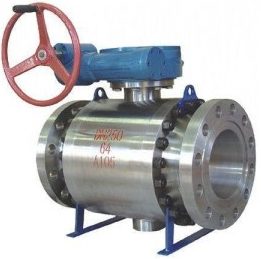
A trunnion ball valve is a type of ball valve that utilizes a fixed ball design to control the flow of fluid. Unlike floating ball valves, where the ball is allowed to float between the valve seats, in trunnion ball valves, the ball is anchored at the top and bottom by trunnions. These trunnions, essentially extensions of the ball or additional support mechanisms, hold the ball in a fixed position while allowing it to rotate.
How It Works
The ball in a trunnion ball valve has a hole through its center. When the valve is open, this hole is aligned with the flow path, allowing fluid to pass through. Turning the valve’s handle or actuator rotates the ball to block the flow path, stopping the flow. The trunnions absorb the line pressure, reducing the load on the valve seats and ensuring a tight seal regardless of pressure fluctuations.
Key Features and Advantages
- Low Operational Torque: Because the ball is supported by trunnions, there’s less friction between the ball and the seats during operation, which translates to lower torque requirements. This makes it easier to operate, especially for larger valve sizes or in high-pressure applications.
- High Pressure and Temperature Capabilities: Trunnion ball valves are well-suited for high-pressure and high-temperature applications. The trunnion design effectively manages the thrust from line pressure, preventing excess stress on the valve components.
- Durability and Reliability: The fixed ball design minimizes wear on the seats and ensures consistent performance over time, contributing to the valve’s longevity and reliability.
- Double Block and Bleed (DBB) Capability: Many trunnion ball valves offer DBB functionality, allowing for maintenance and pressure verification without shutting down the entire system.
Applications
Trunnion ball valves are used in a wide range of industrial applications, especially where high pressure and large diameters are involved, such as:
- Oil and Gas: For controlling flow in pipelines, processing facilities, and offshore platforms.
- Petrochemical and Chemical Manufacturing: In systems requiring robust valves that can handle high pressures and corrosive fluids.
- Power Generation: For steam, water, and feedwater systems within power plants.
- Water and Wastewater Treatment: In high-pressure lines and for applications requiring durable and reliable shut-off.
Considerations
While trunnion ball valves offer several advantages, they are typically more expensive than floating ball valves due to their more complex design and manufacturing process. They are also generally larger and heavier, which may be a consideration for installation and support structures. Despite these factors, their reliability and performance in demanding conditions make them a preferred choice for many high-pressure and large-scale applications.
(Source: Robert Cort – Wartsila Valves Youtube Channel)
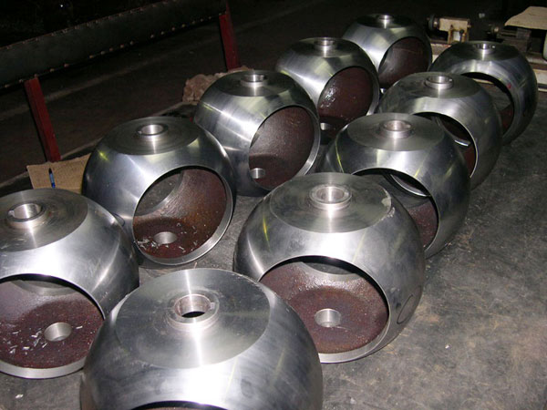
- o the casting operations required to manufacture the body
TOP ENTRY BALL VALVE
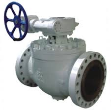
A top entry ball valve is a type of ball valve where the main components, including the ball and seats, can be accessed and serviced from the top of the valve without removing the entire valve body from the pipeline. This design provides a significant advantage in terms of maintenance and repair.
Design and Operation
- Ball Mechanism: Similar to other ball valves, a top entry ball valve uses a spherical ball with a hole through its center to control fluid flow. The valve opens when the ball’s hole is aligned with the flow path and closes when rotated 90 degrees.
- Access: The distinguishing feature of a top entry ball valve is the single-piece body design that allows access to the valve internals through a removable bonnet or cover on the top. This design means that the valve internals can be inspected, repaired, or replaced without detaching the valve body from the pipeline.
- Sealing and Support: Top entry ball valves can be designed with floating or trunnion-supported balls, depending on the application requirements. They also feature robust sealing mechanisms to prevent leaks, which can be easily replaced or serviced due to the top entry design.
Advantages
- Ease of Maintenance: The primary advantage is the ease of maintenance and repair. Valve components can be serviced directly on the line, reducing downtime and operational costs.
- Versatility: Top entry ball valves are suitable for a wide range of applications, pressures, and temperatures. They can be used in critical and high-performance settings, including the oil and gas industry, power generation, and process industries.
- Durability and Reliability: These valves are built for durability and reliability, with designs that can handle high pressure and adverse conditions effectively.
Applications
Top entry ball valves are used in various industrial applications where valve accessibility and ease of maintenance are crucial, especially in high-pressure and high-temperature environments. Common applications include:
- Oil and Gas: For onshore and offshore pipelines, production facilities, and refining processes where rapid maintenance may be required.
- Chemical Processing: In systems handling corrosive or hazardous materials that may require frequent maintenance.
- Power Generation: In feedwater, steam, and other critical power plant systems.
Differences Top-Entry and Side-Entry Ball Valves
Top entry and side entry ball valves are two distinct designs within the ball valve family, each offering specific advantages for different applications. The primary difference lies in how the ball and internal components are accessed and maintained. Here’s a breakdown of each type:
Top Entry Ball Valve
Design: In a top entry ball valve, the ball and seats can be accessed from the top of the valve. The valve body is a single piece, with a removable bonnet or cover on top that provides direct access to the valve internals without removing the valve from the pipeline.
Advantages:
- Maintenance: Allows for easier maintenance, inspection, and replacement of the internals (ball, seats, seals) without detaching the valve from the pipeline, saving time and reducing downtime.
- Application: Suitable for high-pressure and high-temperature applications, as well as in situations where inline maintenance is necessary or where system downtime needs to be minimized.
Considerations:
- Typically more expensive due to the precision engineering required for the top entry design.
- Often used in critical or hard-to-reach areas where valve removal would be challenging.
Side Entry Ball Valve (Split Body Ball Valve)
Design: The side entry ball valve, often referred to as a split body ball valve, features a body that is divided into two or three pieces, bolted together. The ball is inserted from the side when assembling the valve. The body joint is typically along the horizontal axis for a two-piece design and may include a third piece (center piece) for three-piece designs.
Advantages
- Cost-Effectiveness: Generally more cost-effective than top entry valves, making them suitable for a wide range of applications.
- Versatility: Available in a wide variety of sizes and pressure ratings, suitable for many industrial applications.
Considerations
- Maintenance or repair requires the valve to be removed from the pipeline, which can increase system downtime.
- The seal at the body joint may have specific pressure limitations, influencing the valve’s suitability for high-pressure applications.
Key Differences (Top vs. Side Entry)
- Maintenance Accessibility: Top entry valves allow for inline maintenance without removing the valve from the pipeline, while side entry valves need to be fully removed for servicing.
- Construction and Cost: Top entry valves have a one-piece body design that can be more expensive to manufacture, whereas side entry valves have a split body design that is generally more cost-effective.
- Application Suitability: The choice between top entry and side entry may depend on the application’s maintenance requirements, cost considerations, and pressure/temperature demands.
In summary, the decision between a top entry and side entry ball valve often comes down to the specific needs of the application, including maintenance practices, budget constraints, and operational conditions. Each type offers unique benefits that make it suitable for different industrial environments.
Trunnion-mounted ball valves, as well as floating ball valves, are available with a “side entry” and “top entry” design.
The top entry design is specified when frequent inline maintenance activities are expected on the valve.
This is because top-entry ball valves allow easier and faster access to the ball and the valve trim compared to side-entry valves (which require more maintenance time and space for the same operations).
Final Considerations about Top-Etntry Ball Valves
While top-entry ball valves offer significant maintenance advantages, they may come with a higher initial cost compared to other ball valve types due to their design complexity and manufacturing requirements. Additionally, their selection should consider the specific application’s pressure, temperature, and fluid compatibility to ensure optimal performance and longevity.
3-WAYS BALL VALVE (OR “MULTIPORT”)
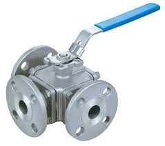
A 3-way ball valve is a type of ball valve designed to control the flow of fluids in three different directions. It is characterized by having three ports (inlet and two outlets, or one inlet and two outlets), making it versatile for various applications where flow diversion, mixing, or directional control is needed. The internal ball typically has either an L-shaped or T-shaped port, allowing for different flow patterns depending on its position.
How It Works
- L-Port Configuration: The L-shaped port connects the center port to one of the side ports at a time, making it suitable for diverting flow from one line to another. By rotating the ball, the valve can alternate between connecting the inlet to either of the two outlets.
- T-Port Configuration: The T-shaped port can connect all three ports simultaneously or block one port while connecting the other two. This configuration is useful for mixing two inlet flows or dividing one inlet flow into two outlets.
Key Features
- Versatility: 3-way ball valves can serve multiple functions, such as stopping and starting flow, changing the flow direction, mixing, or splitting the flow within a single valve body.
- Easy Operation: Like other ball valves, 3-way ball valves offer quick and efficient operation, typically with a quarter-turn mechanism to change flow paths.
- Compact Design: These valves can replace multiple two-way valves and fittings in a system, saving space and reducing potential leak points.
Applications
3-way ball valves are widely used across various industries for different purposes, including:
- Chemical Processing: For directing chemical flows between different processing stages or mixing chemicals.
- HVAC Systems: To control the direction of heating or cooling media.
- Food and Beverage: In systems requiring the diversion of fluids or mixing of ingredients.
- Water Treatment: For directing water flow through different treatment paths.
Selection Considerations
When selecting a 3-way ball valve, consider:
- Flow Requirements: Determine the required flow pattern (L-port or T-port) based on the application’s needs.
- Material Compatibility: Ensure the valve materials are compatible with the fluids being handled, considering factors like corrosion resistance and food safety.
- Pressure and Temperature: Select a valve that can withstand the operating pressure and temperature conditions of the system.
- Actuation: Decide between manual operation or automated actuation (electric, pneumatic, hydraulic) based on system requirements.
In summary, 3-way ball valves offer a flexible and efficient solution for controlling flow directions in a piping system, accommodating a variety of operational needs with simple adjustments.
FULL PORT VS REDUCED PORT BALL VALVES
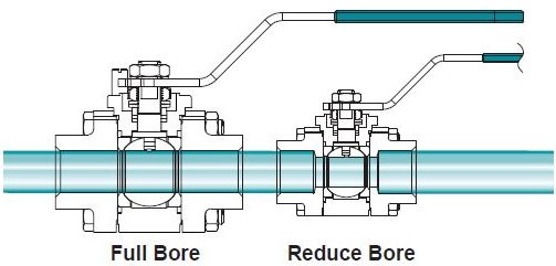
These concepts refer to the relation between the bore diameter of the valve and the connected piping system. The term “port” can be also referred to as “bore” (full bore/small bore).
Full port and reduced port ball valves are two common design variations found in ball valves, each serving specific operational purposes based on flow requirements and pressure drop considerations. Understanding the differences between them is crucial for selecting the appropriate valve type for a particular application.
Full Port Ball Valve (Full Bore)
- Design: In a full port ball valve, the diameter of the ball’s hole (bore) matches the inner diameter of the connecting pipeline. This design ensures that there is no restriction in the flow path when the valve is fully open.
- Advantages: Minimal pressure drop across the valve, which is especially beneficial in applications requiring the preservation of flow rate and pressure. It also allows for pigging operations in pipelines, where a cleaning pig is sent through the pipe to remove debris and buildup.
- Applications: Full port valves are ideal for applications where flow efficiency is critical and for systems that require regular pigging for maintenance.
Reduced Port Ball Valve (Reduced Bore)
- Design: The bore diameter of a reduced port ball valve is smaller than the pipeline’s diameter. This results in a flow path that is somewhat restricted compared to the full port design.
- Advantages: Reduced port valves are generally smaller and less expensive than full port valves of the same nominal size. The smaller bore also requires less torque to operate, which can reduce the size and cost of the actuation mechanism.
- Applications: Suitable for applications where flow rate and pressure drop are less critical. They are commonly used in applications where space and cost savings are desired without significantly compromising the system’s performance.
Key Differences
- Flow Path and Pressure Drop: Full port valves offer an unrestricted flow path, resulting in lower pressure drops, while reduced port valves introduce some restriction and higher pressure drops.
- Size and Cost: Reduced port valves are typically more compact and cost-effective than full port valves, making them attractive for applications where space is limited, and the full flow capacity is not required.
- Operational Efficiency: The choice between full and reduced port often depends on the system’s requirements for flow efficiency and pressure maintenance. Full port valves are preferred in systems that cannot tolerate significant pressure drops or where pipeline pigging is necessary.
In summary, the choice between full port and reduced port ball valves depends on the specific requirements of the application, including considerations of flow rate, pressure drop, operational efficiency, and cost. Understanding these differences ensures the selection of the most appropriate valve type to meet the system’s needs effectively.
V-PORT BALL VALVE
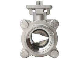
A V-Port ball valve, also known as a V-Ball or V-Notch ball valve, is a specialized type of ball valve designed for more precise flow control and regulation compared to standard ball valves. This valve features a ball with a V-shaped cutout on its surface, giving it the name “V-Port.” The unique shape of the V-Port allows for better throttling control and rangeability, making it particularly suited for applications requiring precise flow modulation.
Design and Operation
- V-Port Design: The angle of the V-notch cut into the ball can vary, typically ranging from 15 to 90 degrees. The shape and angle of the V-Port directly affect the flow characteristics, allowing for linear or equal percentage flow control. As the valve is opened or closed, the V-shaped portion provides a gradual change in flow area, enabling fine adjustment of flow rate.
- Operation: Like other ball valves, V-Port ball valves operate with a quarter-turn mechanism. Rotating the valve handle 90 degrees opens or closes the valve, but the precise shape of the V-Port allows for more nuanced control over the flow as the valve moves between open and closed positions.
Advantages
- Enhanced Flow Control: The V-Port design offers superior control over fluid flow, especially in partially open positions, making it ideal for throttling applications.
- High Rangeability: V-Port ball valves can effectively manage a wide range of flow rates, providing flexibility across various operational conditions.
- Reduced Cavitation and Flashing: The gradual change in flow area helps minimize the risks of cavitation and flashing, common challenges in fluid control applications.
- Durability: V-Port ball valves maintain the inherent durability and reliability of traditional ball valves, suitable for high-pressure and high-temperature applications.
Applications
V-Port ball valves are used in diverse industries where precise flow regulation is required, including:
- Chemical Processing: For controlling the flow of aggressive or corrosive fluids.
- Water and Wastewater Treatment: In applications requiring fine adjustment of water flow.
- Food and Beverage Production: Where precise flow control is necessary for process accuracy.
- Pulp and Paper Manufacturing: For controlling the flow of slurry and other process fluids.
Selection Considerations
When selecting a V-Port ball valve, consider factors such as the specific flow control requirements, the fluid properties (including viscosity and potential for particulate matter), operating pressures and temperatures, and the valve materials’ compatibility with the process fluid.
In summary, V-Port ball valves offer enhanced flow control capabilities, making them a valuable option for applications requiring precise flow regulation. Their design combines the robustness and reliability of standard ball valves with improved performance for throttling and modulation tasks.
SEGMENTED BALL VALVE
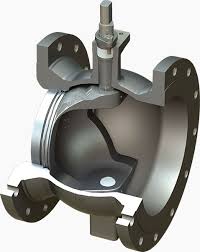
A segmented ball valve, also known as a V-notch ball valve, is a specialized type of ball valve designed to provide precise flow control, especially in applications involving liquids with varying viscosities or slurries. It combines the robust sealing characteristics of a traditional ball valve with enhanced control capabilities, thanks to its unique ball design.
Design
The key feature of a segmented ball valve is its ball segment or V-notch design. The ball has a V-shaped cutout on one side, which gradually opens or closes as the valve is turned, allowing for more precise modulation of flow than a standard ball valve. The “segment” refers to the part of the ball that is cut out, and it can rotate within the valve body to regulate the flow.
How It Works
As the valve handle or actuator is turned, the V-notch segment of the ball rotates, aligning more or less with the flow path. This design allows for a range of flow control, from fully open to nearly closed, with the V-notch providing a shearing action that is effective at controlling the flow of slurry or viscous fluids.
Key Features
- Precise Flow Control: The V-notch design enables finer control over the flow rate, making it suitable for throttling applications.
- Shearing Action: The V-notch can cut through solids and slurries in the fluid, reducing clogging and ensuring smoother operation in challenging conditions.
- High Rangeability: The valve offers a wide range of flow capacities, from fully open to minimal flow, allowing for versatile use across different applications.
- Durability: Segmented ball valves are designed to withstand harsh operating conditions, including high pressures and temperatures.
Applications
Segmented ball valves are used in various industrial applications where precise flow control and durability are required, including:
- Chemical Processing: For handling corrosive fluids, viscous products, or slurry mixtures where precise flow modulation is necessary.
- Pulp and Paper Manufacturing: In processes involving fibrous slurries, where the valve’s shearing action can prevent clogging.
- Water and Wastewater Treatment: For controlling the flow of water with varying levels of particulate matter.
- Food and Beverage: In applications involving viscous liquids or products with solids.
Considerations
When selecting a segmented ball valve, it’s important to consider the specific requirements of your application, including the fluid’s nature, pressure and temperature conditions, and the degree of flow control needed. The material of the valve and its components should be compatible with the process fluid to ensure longevity and reliability.
In summary, segmented ball valves offer an efficient solution for applications requiring precise flow control and the ability to handle difficult fluids, combining the benefits of ball valve sealing with the adjustability of a control valve.
BALL CONTROL VALVE
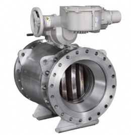
A ball control valve is a type of control valve that uses a ball with a hole through it to regulate the flow of a fluid. It combines the spherical closure element of a traditional ball valve with the ability to modulate flow, making it suitable for precision control applications. Ball control valves are designed to offer variable control of fluid flow, allowing for adjustment from full flow to minimal flow based on the position of the ball.
Design Features
- Rotary Ball: The core component is a rotary ball with a bore through the center. The position of the ball (and thus the alignment of the bore with the flow path) is adjusted to control the flow rate.
- V-Port: Many ball control valves feature a V-shaped cut or notch on the ball or in the bore, enhancing their ability to provide finer control over a wide range of flow rates. The “V” shape allows for more precise control as the valve moves from the closed to the open position.
- Actuation: Ball control valves are often operated by pneumatic, electric, or hydraulic actuators, allowing for remote control and automation of the valve’s position in response to system demands.
Operational Advantages
- Precise Flow Control: Offers excellent control over flow rates, making it ideal for applications where the flow needs to be adjusted or regulated accurately.
- High Rangeability: The design allows for a wide range of flow capacities, enabling precise control from fully open to nearly closed positions.
- Good Shut-Off Capabilities: When fully closed, ball control valves provide a tight seal, similar to standard ball valves, making them suitable for on/off control in addition to flow modulation.
- Durability: The robust design of ball control valves, especially those with hard-sealed components, can handle high-pressure applications and aggressive media.
Applications
Ball control valves are used in a variety of industries and applications, including:
- Process Industries: For controlling the flow of gases, liquids, and even slurries in chemical, petrochemical, and pharmaceutical processes.
- Water Treatment: In systems requiring precise control of water flow, such as in filtration, distribution, and wastewater treatment.
- Oil and Gas: For regulating the flow in pipelines, production processes, and refining operations.
- Food and Beverage: In applications involving the control of liquids and semi-liquids during processing and manufacturing.
Selection Considerations
When selecting a ball control valve, consider factors such as:
- Fluid Compatibility: Ensure the materials of the valve are compatible with the process fluid to prevent corrosion and wear.
- Pressure and Temperature Ratings: The valve must be capable of operating within the system’s pressure and temperature ranges.
- Flow Characteristics: Consider the required flow pattern (e.g., linear or equal percentage) and rangeability to ensure the valve meets the application’s control needs.
In summary, ball control valves are an effective solution for applications requiring both precise flow modulation and reliable shut-off capabilities. Their versatility and durability make them a popular choice in various industrial processes where control accuracy is paramount.
BALL VALVE VS. OTHER TYPES OF VALVES
Ball Valve vs Gate Valve
Ball valves and gate valves are two commonly used types of valves in piping systems, each serving specific purposes with distinct advantages and operational differences. Here’s a comparison to highlight the key aspects of ball valves versus gate valves:
Ball Valve
- Operation: Utilizes a rotating ball with a hole through its center to control flow. Turning the valve’s handle 90 degrees opens or closes the flow path.
- Sealing: Offers a tight seal with low torque, making it suitable for applications requiring a leak-proof operation.
- Flow Control: Provides excellent on/off control but is not typically used for flow modulation, as partial opening can create turbulent flow and potentially damage the valve.
- Pressure Drop: Generally experiences a lower pressure drop when fully open compared to gate valves, due to the straight flow path.
- Applications: Widely used for gas and liquid applications where quick and full shutoff is required, including residential, industrial, and commercial plumbing and water systems.
Gate Valve
- Operation: Operates by lifting a gate out of the path of the fluid. Turning the handle or wheel opens or closes the valve by moving the gate vertically.
- Sealing: When fully open or fully closed, gate valves provide a good seal. However, they are prone to wear and leakage over time, especially in the partially open position.
- Flow Control: Primarily designed for on/off control and not recommended for throttling as the partially open gate can be damaged by the fluid flow.
- Pressure Drop: When fully open, gate valves offer very little resistance to flow, resulting in a minimal pressure drop.
- Applications: Ideal for applications where a straight flow path and minimal restriction are desired, such as in water and wastewater treatment, oil and gas industries, and other situations requiring minimal valve operation.
Key Differences
- Functionality: Ball valves are better for applications requiring fast, frequent operation and tight shutoff. Gate valves are preferred for applications where the valve remains either fully open or fully closed for extended periods.
- Flow Regulation: Ball valves are not suited for precise flow control, while gate valves, although not designed for throttling, can provide finer control when opening and closing.
- Maintenance: Ball valves generally require less maintenance than gate valves, as their design is simpler and more resistant to wear from the turbulent flow.
- Cost: The cost can vary depending on the size, material, and specific application requirements. However, ball valves tend to be more cost-effective for smaller sizes, while gate valves can be more economical for larger diameters.
In summary, the choice between a ball valve and a gate valve depends on the specific requirements of the application, including the need for flow control, frequency of operation, and budget considerations. Each valve type offers distinct advantages that make it suitable for different operational contexts.
Ball Valve vs Globe Valve
Ball valves and globe valves are both critical components used in piping systems for controlling flow, but they have distinct design features, operational mechanics, and applications that make them suited to different tasks.
Here’s a breakdown of the key differences between ball valves and globe valves:
Ball Valve
- Design: Features a spherical disc (the ball) with a hole through its center. The ball rotates within the valve body to open or close the flow path.
- Operation: Operates with a quarter-turn (90-degree) movement, offering quick and easy shutoff. The handle’s position (parallel or perpendicular to the pipe) indicates the valve’s status (open or closed).
- Flow Control: Primarily used for on/off control due to its design. While it can be used for throttling, it’s not as precise as a globe valve for this purpose.
- Sealing: Provides a tight seal with minimal wear over time, making it suitable for applications requiring leak-proof operation.
- Pressure Drop: Generally has a lower pressure drop when fully open, as the flow path is straight through the ball.
- Applications: Widely used in applications requiring fast and frequent operation, including gas, liquid, and even slurry services, due to its robust design and effective sealing.
Globe Valve
- Design: Characterized by a body with a Z-shaped partition and a moveable disc or plug that seats against an opening in the partition to regulate flow.
- Operation: Utilizes a multi-turn stem operation, requiring several turns to open or close, which allows for precise control of the flow rate.
- Flow Control: Excellently suited for throttling and regulating flow due to its design, which allows for fine adjustments of the disc position.
- Sealing: Effective sealing capabilities, but the design can lead to more wear on the seating surface due to the disc’s sliding motion against the seat.
- Pressure Drop: Typically experiences a higher pressure drop compared to ball valves because of the tortuous flow path.
- Applications: Commonly used in applications requiring precise flow control, such as in heating and cooling systems, and in processes where flow needs to be adjusted regularly.
Key Differences
- Functionality and Control: Ball valves are best for quick, on/off control but can offer some throttling capabilities. Globe valves excel in applications requiring precise flow regulation.
- Pressure Drop: Ball valves have a lower pressure drop in the open position due to the straight-through flow path, making them more efficient for certain applications. Globe valves, with their Z-shaped flow path, incur a higher pressure drop but provide better flow control.
- Operational Speed: Ball valves can be operated quickly with a quarter-turn, making them suitable for emergency and safety-related applications. Globe valves require multiple turns, offering slower but more precise control.
Choosing between a ball valve and a globe valve depends on the specific needs of the application, including the type of control required (on/off vs. throttling), operational efficiency (pressure drop concerns), and the fluid service conditions (temperature, pressure, and corrosiveness).
Ball Valve vs. Butterfly Valve
Ball valves and butterfly valves are both popular choices for controlling the flow of fluids in piping systems, but they have distinct features, operating mechanisms, and suitability for different applications. Understanding their differences is key to selecting the most appropriate valve for a specific use case.
Ball Valve
- Design: Features a spherical disc (the ball) with a hole through its center. The ball rotates within the valve body to open or close the flow path.
- Operation: Utilizes a quarter-turn mechanism for operation, allowing for quick and easy shutoff. The handle’s position directly indicates the valve’s open or closed status.
- Sealing: Typically offers excellent sealing capabilities due to the tight fit between the ball and the valve seats, making it suitable for gas and high-pressure applications.
- Flow Control: While primarily used for on/off control, some ball valves are designed for flow regulation. However, they are not as precise in controlling flow as butterfly valves.
- Pressure Drop: When fully open, ball valves usually present a minimal pressure drop because the hole in the ball allows for nearly unrestricted flow.
Butterfly Valve
- Design: Consists of a flat disc that rotates around a central axis within the valve body. The disc’s position relative to the flow direction controls the fluid passage.
- Operation: Also operates with a quarter-turn mechanism, allowing for rapid opening and closing. The lever or gear operator indicates the valve’s position.
- Sealing: Offers good sealing with the use of elastomeric seat materials but may not be as tight as a ball valve, especially under high-pressure conditions.
- Flow Control: Excellently suited for throttling applications due to the ease with which the disc can be positioned to regulate flow. Provides more precise flow control compared to ball valves.
- Pressure Drop: Even when fully open, the presence of the disc within the flow path means butterfly valves typically have a higher pressure drop than ball valves.
Key Differences
- Application Suitability: Ball valves are preferred for applications requiring tight shutoffs, such as in gas transmission and high-pressure scenarios. Butterfly valves are favored in applications where precise flow control and regulation are necessary, especially in larger diameter pipes where ball valves would be impractical or too expensive.
- Operational Efficiency: Ball valves provide a more secure seal and are generally more effective for on/off control, while butterfly valves offer superior capabilities for flow modulation and adjustment.
- Cost and Space Considerations: Butterfly valves tend to be more cost-effective for larger sizes and require less space for installation due to their compact design compared to ball valves.
The choice between a ball valve and a butterfly valve ultimately depends on specific factors like the fluid’s nature, pressure, and temperature conditions, required flow control precision, space availability, and budget constraints. Each valve type has its advantages and ideal use cases, ensuring optimal performance for various applications.
MATERIALS FOR BALL VALVES
Cast vs. Forged Ball Valves Body Materials
Ball valves are manufactured either with cast or forged body materials (which can be monoblock, or split, body types).
When Forged Bodies?
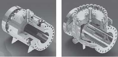
Generally, ball valves below 2 inches in diameter are manufactured in 2 pieces or 3 pieces body configurations (the most common materials used for forged ball valves are ASTM A105 for high-temperature service, ASTM A350 LF2/LF3 for low-temperature service, and ASTM A182 F304/F316 for stainless steel valve or higher grades, such as duplex valves ASTM A182 F51 and super duplex ASTM A182 F53/F55).
Forged bodies are also used for high-pressure valves of higher bore sizes (with 2 or 3-piece split body construction).
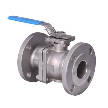
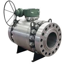
Examples of forged ball valves (small size and stainless steel valve with a forged body, trunnion mounted).
When Cast Bodies?
Valves in sizes above 2 inches are generally manufactured with cast body materials (the most common grades are ASTM A216 WCB for high temp. service, ASTM A352 for low-temperature service and ASTM A351 CF8, CF8M for cast stainless steel valves).
ASTM Materials for Ball Valves
- Carbon Steel: ASTM A216 WCB is a common grade used for the valve body in moderate temperature applications. It offers good strength and toughness.
- Stainless Steel: ASTM A351 CF8M (equivalent to SS316) and ASTM A351 CF8 (equivalent to SS304) are widely used for corrosion resistance in harsh environments.
- Alloy Steel: ASTM A494 CW-6MC (Inconel 625), ASTM A494 CW-12MW (Hastelloy C), and other alloys are used for high-temperature and high-corrosion applications.
- Bronze and Brass: ASTM B62 (Bronze) and ASTM B16 (Brass) are used for general low-pressure applications and are particularly common in plumbing and water systems.
API Materials for Ball Valves
- API 608: Specifies the requirements for ball valves used in the petroleum and natural gas industries. This standard covers material requirements for different classes of service, including carbon steel, stainless steel, and alloy materials.
- API 6D: While primarily a specification for pipeline valves (including gate, plug, and ball valves), API 6D also outlines material specifications for ball valves used in pipeline applications. Materials are chosen based on the pressure and temperature class of the valve.
Material Selection Considerations
- Corrosion Resistance: Stainless steel and alloy materials are selected for services involving corrosive fluids, while carbon steel may be sufficient for water, steam, and oil where corrosion is not a significant concern.
- Temperature and Pressure: High-temperature and high-pressure applications may require alloy steels or special alloys to maintain integrity under extreme conditions.
- Compatibility: The material must be compatible with the fluid to prevent contamination or degradation of the valve components.



14 Responses
This article gave me such a valuable insight. The breakdown of different Ball valve types and materials used was incredibly helpful. If anyone’s curious to know more about top Ball valves Supplier check out valvulasfevisa. They can help you with the best quality industrial valves. Thanks to the author for making this complex topic so accessible!
Thank you for your kind words! We’re glad to hear that our article provided you with valuable insight into the different types of ball valves and the materials used in their manufacturing. It’s great to know that you found the breakdown helpful.
If anyone is interested in learning more about top ball valve suppliers, we recommend checking out valvulasfevisa. They specialize in providing high-quality industrial valves and can assist you in finding the best solutions for your needs.
We appreciate your recognition of our effort in making this complex topic accessible. If you have any further questions or if there’s anything else we can assist you with, please feel free to reach out.
For more information on forged steel sloating ball valve for oil and gas project. Please visit https://www.athenavalve.com/
Hey, I would love to put my comment on this awesome blog post!
I was totally confused about what is ball valves how it is work but after reading your blog post it is clear.
Thanks for sharing the quality content worldwide!
The article is informative. Very detailed. We manufacture all these range from High pressure & Trunion mounted ball valves to standard basic application ball valve. visit us: https://www.hubluxe.com
list for me all types of ball valve in plumbing
Goodday.
Please I need a hand with this valves
Ball valve- 6″ Body SA 150- Ball/STEM SS- SEAT PEEK- Full Body Trunnion Ball 600# SORF
Ball valve- 4″ Body SA 150- Ball/STEM SS- SEAT PEEK- Full Body Trunnion Ball 600# SORF
Contact me via e-mail
We are Zhejiang Longcheng Forging Co., Ltd, and specialized in ball valves. pls contact me at alice@lcforging.net if you have any needs.
the best ball valve guide and i have never ever seen this type detailed information yet.
Thank you so much for the sharing. also please check my content at https://www.airaindia.com/valve-automation/ball-valve-manufacturer-and-exporters/
For more information on trunnion ball valves for oil and gas project. Please visit http://www.trunnionballvalve.net
This blog is very usefull to understand the ball valves.
“AMCO” Ball Valves are Manufactured with Full Port/Regular Port constructions. When a Ball Valve is chosen to replace a Gate Valve, the obvious choice is a Full Port Ball Valve.
http://amcovalves.com/products/ball-valves/
what is the maximum allowable clearance between the valve flange and the flange of the pipe line to where the valve to connected. in case of a 3inch 2500 class valve operating at a pressure of 5000psi gas pressure @ a temperature of 60deg C
Dear Sir,
We have a regular requirement of Trunnion Ball valves.
Please contact us on https://www.kanchansales.com
It will be a pleasure to work with a industry leader
We are Zhejiang Longcheng Forging Co., Ltd, and specialized in ball valves. pls contact me at alice@lcforging.net if you have any needs.