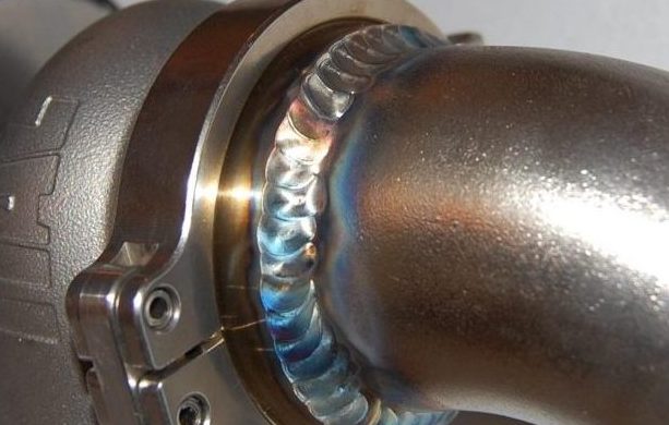
A fillet weld is defined, by the American Welding Society (AWS), as “A weld of approximately triangular cross-section joining two surfaces approximately at right angles to each other in a lap joint, T-joint, or corner joint.” This type of welding technique is used to connect socket weld fittings or slip-on flanges to pipes.
FILLET WELD
WHAT IS A FILLET WELD?
A fillet weld is a type of weld used to join two pieces of metal together at a right angle or where the pieces join at an angle other than 180 degrees.
In the context of forged fittings in piping systems, fillet welds are commonly used to secure socket-weld fittings to pipe. Unlike butt welds, which join two pieces along their edges in the same plane, fillet welds join two surfaces at an angle, filling the gap with weld material to form a triangular cross-section.
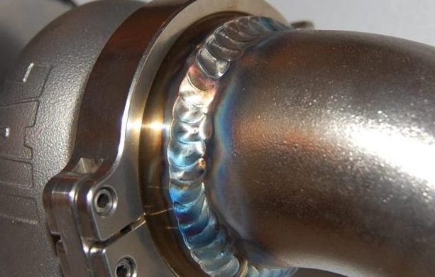
Application in Forged Fittings
- Socket-Weld Fittings: Forged fittings such as elbows, tees, couplings, and valves often use socket-weld connections. The pipe is inserted into the recessed area of the fitting (the socket), and a fillet weld is applied around the top of the socket, joining the outer surface of the pipe to the fitting. This type of weld is crucial for creating a strong, leak-proof connection in high-pressure and high-temperature applications.
Characteristics of Fillet Welds for Forged Fittings
- Strength: Fillet welds provide significant strength, making them suitable for dynamic loads and high-pressure applications within piping systems.
- Versatility: This welding technique can be used on various materials and in different positions, offering flexibility in the installation and maintenance of piping systems.
- Efficiency: Fillet welding is generally faster and requires less preparation than butt welding, making it an efficient choice for many applications.
Key Considerations
- Weld Size: The size of the fillet weld (leg length) must be appropriate for the pressure and mechanical load requirements of the piping system. It’s determined based on the thickness of the pipe and fitting walls.
- Weld Quality: Proper technique and control are vital to prevent defects such as undercutting, incomplete fusion, or porosity, which could compromise the integrity of the connection.
- Material Compatibility: The filler material used in the weld must be compatible with the materials of the pipe and fitting to ensure cohesive metallurgical properties and corrosion resistance.
- Inspection and Testing: After welding, inspections (visual or non-destructive testing) may be necessary to ensure the weld meets the required standards and specifications for safety and performance.
In piping systems, fillet welds are essential for attaching socket-weld forged fittings securely, providing a durable and reliable method for assembling high-pressure and high-temperature pipelines. The success of these connections relies on proper welding practices, adherence to specifications, and regular inspection to maintain the integrity of the piping network.
TYPES OF FILLET WELDS
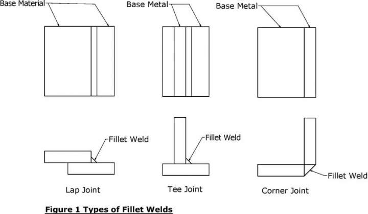
Here’s a look at the types of fillet welds, particularly in the context of lap joint, tee joint, and corner joint configurations:
1. Lap Joint
- Description: A lap joint occurs when two pieces of metal are overlapped and welded at the edges. This joint is commonly used when joining two pieces of metal of different thicknesses.
- Fillet Weld Application: In a lap joint, the fillet weld is applied along the side where the two pieces overlap. The weld can be on one or both sides, depending on the strength requirements. This type of weld is straightforward because it doesn’t require any special preparation of the metal edges.
2. Tee Joint
- Description: A tee joint is formed when the end of one piece of metal is joined to the side of another piece to form a “T” shape. This joint is prevalent in frame structures and piping systems.
- Fillet Weld Application: Fillet welds are applied at the intersection where the two pieces meet. Depending on the loading requirements, welds can be made on one or both sides of the stem of the “T.” This is a common scenario for attaching forged fittings to pipe systems, ensuring a secure connection.
3. Corner Joint
- Description: Corner joints are used to join two metal parts at their edges to form a corner. This joint type is often found in box or frame structures.
- Fillet Weld Application: The fillet weld is applied in the internal or external corner formed by the two pieces. Like the lap and tee joints, corner joints can be welded on one or both sides, depending on structural requirements. The weld fills the corner, joining the two parts without the need for edge preparation.
Key Considerations for Fillet Welds
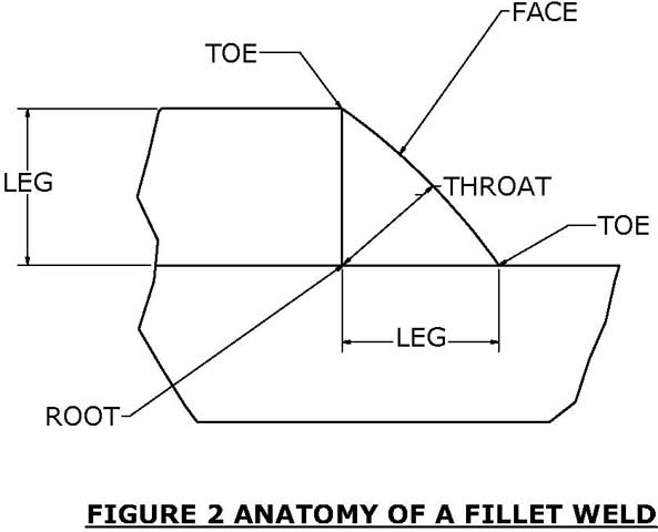
- Weld Size: The size of the fillet weld is crucial for ensuring adequate strength. It’s determined by the legs of the weld, which should be equal in a well-formed fillet weld.
- Weld Length: Depending on the application, fillet welds can be continuous along the entire joint or intermittent to save on welding material and reduce heat input.
- Material Compatibility: Ensure that the welding material is compatible with the metals being joined to prevent corrosion or weakening of the joint.
- Inspection and Testing: Especially in critical applications, fillet welds should be inspected for quality and tested for integrity using methods appropriate to the application and materials.
Fillet welds for forged fittings in piping systems are essential for creating strong, durable connections capable of withstanding operational pressures and temperatures. Understanding the types of joints and the application of fillet welds is critical for the design and maintenance of reliable piping systems.
The basic fillet weld symbol consists of a reference line, an arrow line, the tail, Weld Procedure Specification (WPS) information, and the fillet weld symbol including leg size. The most common elements of this type of weld are shown in the picture below.
The reference line is always drawn horizontally, it contains the weld type information and connects the arrow line and the tail. The arrow line points to the weld location.
The underside of the reference line is referred to as the arrow side, weld symbols drawing on this side of the reference line are placed to the arrow side of the components; weld symbols located above the reference line are placed on the components to the side opposite the arrow.
The tail is actually an optional element and contains information regarding the weld. The WPS identifies the procedures and parameters that the welder uses to execute the weld. Notes and other information on the weld can be included in the tail.
The fillet weld symbol is represented as a triangle. The leg size of the fillet weld is placed to the left of the fillet symbol.
Most, but not all fillet welds are of equal legs. When the legs are not equal the leg sizes are indicated for example by 1 x 1.25.
At the juncture of the reference line and tail, a circle indicates the welding goes entirely around the feature the arrow line is pointing at. Commonly applied to circular features, this instruction is not limited to them.
A darkened flag at the juncture of the reference line and tail indicates the weld is to be performed in the field.
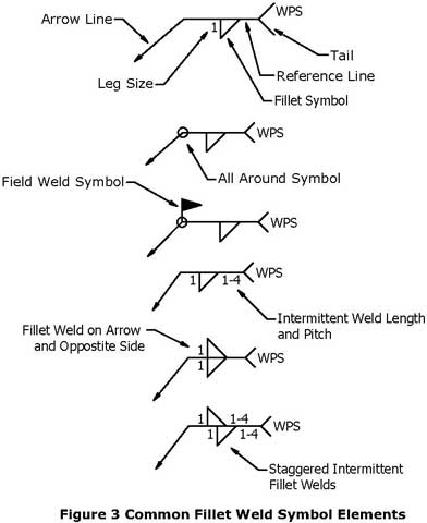
Fillet welds do not have to be continuous, the length and pitch between centers of an intermittent fillet weld are shown to the right of the welding symbol. Fillets welds are not necessarily limited to one side of the components to be joined.
Fillet welds can be made on both the arrow side and opposite side of the components. These welds could be continuous or intermittent.
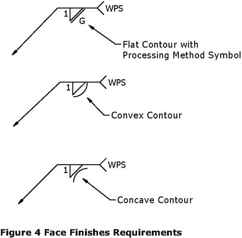
The face of a fillet weld can be required to be flat, convex, or concave. If the face requires finish processing it could be chipped (C), ground (G), hammered (H), machined (M), rolled (R), or peened (P) as shown in the picture:
