Threaded Flange Sizes (EN 1092-1)
EN 1092-1 Threaded Flange Dimensions and Weights
What Is a “Type 13” EN 1092-1 Threaded Flange?
“Type 13” according to EN 1092-1 designates a hubbed threaded flange. Unlike the standard weld neck flange (Type 11) that requires welding, Type 13 flanges feature internal threads that allow them to be screwed directly onto an externally threaded pipe. The hub provides additional strength and rigidity, distributing stress more evenly across the connection.
| Feature | Description |
|---|---|
| Design | Hubbed flange with internal threads (ISO 7-1) |
| Connection | Screwed onto externally threaded pipe; no welding required |
| Applications | Low to moderate P/T; where welding is not feasible or poses safety risks |
| Materials | Carbon steel, stainless steel, alloy steel per EN 1092-1 |
| Sizes | DN 15 to DN 150 |
| Pressure ratings | PN 6 and PN 16 |
Advantages
| Advantage | Description |
|---|---|
| Ease of installation | Threaded connection allows quick assembly and removal without welding equipment |
| No welding required | Convenient for settings where welding poses safety risks (e.g., explosive environments) |
| Hub strength | Hubbed design distributes stress evenly, enhancing connection integrity |
Dimensions and Weights of EN 1092-1 THD Flanges
THD Flange PN 6
PN 6 threaded flange dimensions (EN 1092-1 type 13) with stud metric bolts and nuts requirements (sizes in millimeters)
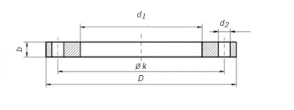
| DN | d1 | Thread | k | D | b | h1 | d3 | d4 | f | d2 | Bolt Thread | Bolt Holes | Weight (KG) |
|---|---|---|---|---|---|---|---|---|---|---|---|---|---|
| 15 | 21,3 | R 1/2″ | 55 | 80 | 12 | 20 | 30,0 | 40,0 | 2,0 | 11 | M10 | 4 | 0,373 |
| 20 | 26,9 | R 3/4″ | 65 | 90 | 14 | 24 | 40,0 | 50,0 | 2,0 | 11 | M10 | 4 | 0,584 |
| 25 | 33,7 | R 1″ | 75 | 100 | 14 | 24 | 50,0 | 60,0 | 2,0 | 11 | M10 | 4 | 0,729 |
| 32 | 42,4 | R 1-1/4″ | 90 | 120 | 14 | 26 | 60,0 | 70,0 | 2,0 | 14 | M12 | 4 | 1,040 |
| 40 | 48,3 | R 1-1/2″ | 100 | 130 | 14 | 26 | 70,0 | 80,0 | 3,0 | 14 | M12 | 4 | 1,200 |
| 50 | 60,3 | R 2″ | 110 | 140 | 14 | 28 | 80,0 | 90,0 | 3,0 | 14 | M12 | 4 | 1,340 |
| 65 | 76,1 | R 2-1/2″ | 130 | 160 | 14 | 32 | 100,0 | 110,0 | 3,0 | 14 | M12 | 4 | 1,830 |
| 80 | 88,9 | R 3″ | 150 | 190 | 16 | 34 | 110,0 | 128,0 | 3,0 | 18 | M16 | 4 | 2,750 |
| 100 | 114,3 | R 4″ | 170 | 210 | 16 | 40 | 130,0 | 148,0 | 3,0 | 18 | M16 | 4 | 3,010 |
| 125 | 139,7 | R 5″ | 200 | 240 | 18 | 44 | 160,0 | 178,0 | 3,0 | 18 | M16 | 8 | 4,300 |
| 150 | 168,3 | R 6″ | 225 | 265 | 18 | 44 | 185,0 | 202,0 | 3,0 | 18 | M16 | 8 | 4,630 |
THD Flange PN 16
PN 16 threaded flange dimensions (EN 1092-1 type 13) with stud metric bolts and nuts requirements Sizes in millimeters
| DN | d1 | Thread | k | D | b | h1 | d3 | d4 | f | d2 | Bolt Thread | Bolt Holes | Weight (KG) |
|---|---|---|---|---|---|---|---|---|---|---|---|---|---|
| 15 | 21,3 | R 1/2″ | 65 | 95 | 16 | 22 | 35,0 | 45,0 | 2,0 | 14 | M12 | 4 | 0,722 |
| 20 | 26,9 | R 3/4″ | 75 | 105 | 18 | 26 | 45,0 | 58,0 | 2,0 | 14 | M12 | 4 | 1,040 |
| 25 | 33,7 | R 1″ | 85 | 115 | 18 | 28 | 52,0 | 68,0 | 2,0 | 14 | M12 | 4 | 1,250 |
| 32 | 42,4 | R 1-1/4″ | 100 | 140 | 18 | 30 | 60,0 | 78,0 | 2,0 | 18 | M16 | 4 | 1,810 |
| 40 | 48,3 | R 1-1/2″ | 110 | 150 | 18 | 32 | 70,0 | 88,0 | 3,0 | 18 | M16 | 4 | 2,060 |
| 50 | 60,3 | R 2″ | 125 | 165 | 18 | 28 | 84,0 | 102,0 | 3,0 | 18 | M16 | 4 | 2,390 |
| 65 | 76,1 | R 2-1/2″ | 145 | 185 | 18 | 32 | 104,0 | 122,0 | 3,0 | 18 | M16 | 4 | 2,970 |
| 80 | 88,9 | R 3″ | 160 | 200 | 20 | 34 | 118,0 | 138,0 | 3,0 | 18 | M16 | 8 | 3,780 |
| 100 | 114,3 | R 4″ | 180 | 220 | 20 | 40 | 140,0 | 158,0 | 3,0 | 18 | M16 | 8 | 4,380 |
| 125 | 139,7 | R 5″ | 210 | 250 | 22 | 44 | 168,0 | 188,0 | 3,0 | 18 | M16 | 8 | 6,070 |
| 150 | 168,3 | R 6″ | 240 | 285 | 22 | 44 | 195,0 | 212,0 | 3,0 | 22 | M20 | 8 | 7,240 |
Threading Specifications for EN1092-1 Type 13 Flanges
EN 1092-1 flanges, specifically those requiring threading like the Type 13 hubbed threaded flanges, typically follow the ISO 7-1 standard for threading.
This standard specifies the requirements for ISO metric screw threads with the designation “Rp” for internal threads. ISO 7-1 is widely used for pipe threads where pressure-tight joints are made on the threads themselves. The threading is designed to ensure compatibility and a secure fit between interconnected piping components.
ISO 7-1 Threading Specifications
- Type: Taper external threads and parallel internal threads. The standard specifies dimensions, tolerances, and designation for both types of threads.
- Sealing Mechanism: The threads themselves can form a pressure-tight joint, not necessarily requiring additional sealing methods (e.g., gaskets) when properly engaged. However, in practice, some form of thread sealant (like PTFE tape or thread sealing compound) is often used to ensure a leak-proof connection.
- Compatibility: Designed for general use in joining and sealing pipes and fittings. The standardized dimensions facilitate the interchangeability of components across different manufacturers and systems.
For EN 1092-1 Type 13 flanges, the threading allows for direct screwing onto corresponding externally threaded pipe ends, making installation and removal straightforward without the need for welding. This type of connection is particularly advantageous for applications where frequent disassembly might be required or where welding is not feasible.
When specifying or working with EN 1092-1 Type 13 flanges (or any threaded piping components conforming to European standards), verify that the threading conforms to ISO 7-1 to guarantee compatibility and a secure, pressure-tight connection.
Leave a Comment
Have a question or feedback? Send us a message.