
GASKETS FOR FLANGES
WHAT ARE GASKETS FOR FLANGES?
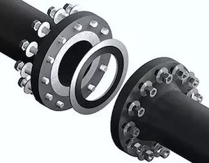
A flange gasket is a type of sealing component designed to fit between two sections of pipe that are flanged together.
Flanges are external or internal ridges that are used for strength or for the attachment of a component, like a pipe. The primary purpose of a flange gasket is to prevent leaks by providing a sealed interface between the two flange faces, ensuring no fluids or gases can escape from the flanged joint.

Key Characteristics of Flange Gaskets:
Material Composition: Flange gaskets are made from a wide range of materials, including rubber, non-asbestos synthetic fibers, metal, silicone, PTFE (polytetrafluoroethylene), and graphite, among others. The choice of material depends on the application, including factors such as the type of fluid being sealed, operating temperature, pressure conditions, and chemical compatibility.
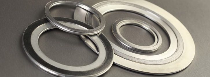
Shape and Size: They are typically circular to match the shape of the flanges, with bolt holes aligned to match the flange pattern. Gaskets come in various sizes and thicknesses to suit different flange standards and specifications, such as those outlined by ASME B16.5 or EN 1092-1.
Types of Flange Gaskets: There are several types of flange gaskets, including flat or sheet gaskets, which are simple and used in low-pressure environments; spiral-wound gaskets, which are suitable for higher-pressure and higher-temperature applications; ring-type joints, which are used in high-pressure situations; cam profile and metal-jacketed gaskets, which offer robust sealing for a wide range of temperatures and pressures. All these types are reviewed in detail in this article.
Gaskets Function and Application:
Sealing Function: The primary role of a flange gasket is to create a tight seal between two flange faces, preventing the escape of fluids and maintaining the integrity of the piping system.
Versatility: Flange gaskets are used across various industries, including oil and gas, chemical processing, power generation, and water treatment. They are critical components in pipelines, tanks, and vessels that transport or store liquids and gases.
Pressure and Temperature Resistance: Different gasket materials and designs can withstand various levels of pressure and temperature, making it crucial to select the right gasket type based on specific operational conditions.
In summary, flange gaskets are essential components in piping systems, ensuring leak-free connections between flanged pipe sections. Their effectiveness in sealing joints makes them indispensable in maintaining operational efficiency, safety, and environmental compliance across many industries.
WHY ARE GASKETS IMPORTANT IN PIPING SYSTEMS?
Gaskets for flanges play a crucial role in the integrity, safety, and efficiency of piping systems across various industries, including oil and gas, chemical processing, power generation, and water treatment. These components are essential for creating tight, leak-proof seals between flange connections, ensuring the safe and effective transport of fluids and gases. Below are detailed reasons why gaskets for flanges are important:
1. Preventing Leaks:
- Safety and Environmental Protection: Gaskets prevent hazardous materials, such as chemicals or hydrocarbons, from leaking into the environment, thus protecting ecosystems and reducing the risk of accidents and health hazards.
- Operational Integrity: By ensuring a leak-proof seal, gaskets maintain the pressure and flow characteristics within the system, crucial for process efficiency and reliability.
2. Withstanding Harsh Conditions:
- Pressure and Temperature Tolerance: Gaskets are designed to withstand the operational pressures and temperatures of the system they are part of. High-performance materials can tolerate extreme conditions without degradation, maintaining a seal under varying or extreme conditions.
- Chemical Compatibility: The materials used for gaskets are selected based on their resistance to the chemicals they will be exposed to, preventing material breakdown and ensuring long-term sealing performance.
3. Facilitating System Maintenance and Flexibility:
- Ease of Maintenance: Flange gaskets allow for the disassembly and reassembly of pipe sections without damage. This is crucial for routine maintenance, inspections, or system modifications.
- System Adaptability: The use of gaskets in flange connections enables the connection of dissimilar materials and the easy addition or removal of sections of the piping system, providing flexibility in system design and expansion.
4. Reducing Costs:
- Leak Prevention: By preventing leaks, gaskets save costs associated with lost products, environmental fines, and cleanup efforts.
- Maintenance Costs: The ability to reuse flanges and only replace gaskets during maintenance reduces the need for expensive component replacements.
5. Improving Performance:
- Sealing Efficiency: Proper gasket selection and installation improve the overall efficiency of the piping system by ensuring optimal pressure conditions are maintained, which can enhance the performance of pumps and other system components.
- Vibration Damping: Some gasket materials can dampen vibrations within the system, reducing noise and wear on components.
6. Customization and Versatility:
- Wide Range of Materials: Gaskets are available in various materials, including rubber, PTFE, graphite, and metals, allowing for customization based on specific application needs.
- Design Versatility: Gaskets can be designed and cut to fit any flange size and shape, making them versatile for standard and custom applications.
SPECIFICATIONS FOR GASKETS (ASME/API)
ASME (American Society of Mechanical Engineers) and API (American Petroleum Institute) provide specifications and standards for gaskets used in piping systems, pressure vessels, and related equipment, particularly in the oil, gas, and petrochemical industries. These specifications ensure gaskets perform effectively under various operational conditions, contributing to the safety, reliability, and efficiency of industrial processes.
Here’s an overview of some key ASME and API specifications relevant to gaskets:
ASME Specifications for Gaskets
ASME B16.20: This standard covers metallic gaskets for pipe flanges in the raised face, flat face, and ring joint configurations. It includes spiral wound gaskets, metal-jacketed gaskets, and ring-type joint gaskets (RTJ). ASME B16.20 specifies dimensions, materials, and application guidelines.
ASME B16.21: This specification details non-metallic flat gaskets for pipe flanges. It covers materials such as compressed fiber sheets, PTFE, and flexible graphite, providing dimensions and tolerances for various flange sizes and pressure classes.
API Specifications for Gaskets
API 6A: This specification, titled “Specification for Wellhead and Christmas Tree Equipment,” includes requirements for ring-type joint gaskets used in high-pressure and high-temperature oil and gas production environments. It defines dimensions, materials, and performance criteria for RTJ gaskets.
API 622: Titled “Type Testing of Process Valve Packing for Fugitive Emissions,” this standard, while focused on valve packing, indirectly affects gasket selection and usage in ensuring low emission levels in valves. It sets testing requirements to evaluate the performance of packing materials under various conditions.
API 600: While primarily focused on steel gate valves for the petroleum and natural gas industries, API 600 also references gasket dimensions and materials compatible with the valve design standards, highlighting the importance of gasket selection in valve integrity and performance.
Let’s now delve into the different types of gaskets for flanges used in the oil & gas and processing industries.
NON-ASBESTOS GASKETS (“SOFT”)
WHAT ARE NON-ASBESTOS GASKETS?
Non-asbestos gaskets are, in general terms, sealing devices used between two surfaces to prevent leaks of liquids or gases in various applications, especially in piping (in the context of flanged joints), machinery, and equipment.
The terms, “flat-cut gaskets”, “die-cut gaskets”, “compressed sheet gaskets”, “compressed-fiber gaskets” and “asbestos-free gaskets” are synonyms to define this first type of gaskets for flanges, and can be interchanged.

Non-asbestos gaskets are the simplest type of gasket for flanges and are produced by cutting graphite, organic, or inorganic non-asbestos sheets into a round-gasket shape (generally, with water jet cutting machines). The two main types of non-asbestos gaskets for flanges are the “full face” (FF) for FF flanges and the “flat ring” type for raised face flanges (RF). These two key sub-types are shown in the image below:

In piping systems, non-asbestos gaskets are used in low-pressure, low-temperature, and non-critical applications, i.e. they represent an entry-level alternative.
The ASME B16.21 specification covers non-asbestos sheet gaskets for flanges and flanged joints (types, sheet materials, dimensions, dimensional tolerances, and marking requirements).
Non-asbestos gaskets are designed to replace asbestos-containing gaskets, which were widely used in the past due to their durability, heat resistance, and sealing capabilities but have since been phased out (in the 70s) due to health risks associated with asbestos exposure, including respiratory issues and serious illnesses like asbestosis and mesothelioma.
Composition and Features:
Non-asbestos gaskets are made from a combination of synthetic fibers, such as Aramid (a strong and heat-resistant synthetic fiber), fiberglass, and elastomeric materials like nitrile rubber, EPDM, or Neoprene. These components are mixed and bound together to create a sheet material that can be cut and shaped into gaskets. The specific composition of a non-asbestos gasket can vary depending on the manufacturer and the intended application, allowing for customization to meet different sealing requirements.
Advantages:
- Health and Safety: The primary advantage of non-asbestos gaskets is their safety; they do not pose the health risks associated with asbestos fibers.
- Versatility: These gaskets can be engineered to suit a wide range of applications, offering resistance to various chemicals, temperatures, and pressures.
- Durability: Non-asbestos gaskets are designed to be durable and withstand harsh operational conditions, similar to their asbestos counterparts.
- Environmental Compliance: Using non-asbestos materials aligns with global regulations and standards aimed at reducing health risks and environmental impact.
Applications:
Non-asbestos gaskets are used in a variety of settings, including:
- Piping Systems: For sealing flanges in water, gas, and chemical pipelines.
- Automotive Industry: In engines, transmissions, and other systems requiring durable seals.
- Industrial Machinery: For sealing joints in pumps, valves, and other equipment.
- HVAC Systems: In heating, ventilation, and air conditioning units to prevent leaks.
Selection Considerations:
When selecting a non-asbestos gasket, consider factors such as:
- Operating Temperature and Pressure: Ensure the gasket material can withstand the specific conditions of the application.
- Chemical Compatibility: The gasket material should resist the chemicals it will be exposed to, preventing degradation and failure.
- Compliance and Certifications: Choose gaskets that meet relevant industry standards and certifications for quality and performance.
COMMON MATERIALS FOR SOFT GASKETS

Introduction
Non-asbestos gaskets for flanges are made from a variety of synthetic materials that provide similar or superior performance to asbestos gaskets without health risks. These materials are selected for their ability to withstand various industrial conditions, including different temperatures, pressures, and chemical exposures.
The most common materials used to manufacture compressed-fiber gaskets are Aramid fibers (Kevlar), Teflon (PTFE), graphite, glass fibers, elastomers, and Neoprene mixed with a multitude of binder materials (the most common binder is NBR, i.e. Buna-N):
- Aramid NBR binder
- Carbon graphite reinforced
- Glass reinforced (steam service gasket)
- PTFE bi-axially oriented (silica filler)
- SBR (styrene-butadiene)
- CR-chloroprene (Neoprene)
- EPDM gasket (ethylene propylene)
- Fluorocarbon (Viton)
- Graphite
- BUNA-n-rubber (nitrile, NBR gasket)
- Chlorosulfonated polyethylene (Hypalon gasket)
- Aramid + SBR binder (premium type gasket)
- Graphite + ss316/316l insert
- PTFE biaxially oriented (with hollow glass microsphere) blue
- PTFE biaxially oriented (pigment-free)-gray
- expanded PTFE gasket
- PTFE joint sealant
- PTFE envelope slit type
- PTFE envelope milled type
- PTFE envelope formed type
- MICA sheet
- Ceramic fiber
Key Non-Asbestos Materials
The key features of the key classes of materials listed above are:
Aramid Fiber:
- Characteristics: Aramid fibers are known for their strength, heat resistance, and durability. They are often used as a replacements for asbestos.
- Applications: Ideal for use in environments with high mechanical stress and where thermal stability is required.
PTFE (Polytetrafluoroethylene):
- Characteristics: PTFE is highly resistant to chemicals and has a very low coefficient of friction. It is stable across a wide range of temperatures.
- Applications: Suitable for applications involving aggressive chemicals, such as strong acids and bases, or where cleanliness and non-contamination are critical, such as in the food and pharmaceutical industries.
Graphite:
- Characteristics: Graphite gaskets offer excellent thermal stability, high compressibility, and good resistance to most chemicals.
- Applications: Used in high-temperature applications, such as exhaust systems, steam services, and where fire safety is a concern.
Elastomeric Compounds:
- Nitrile Rubber (NBR): Resistant to oils, fuels, and some chemicals. Used in applications involving oil and hydrocarbons.
- Ethylene Propylene Diene Monomer (EPDM): Has excellent resistance to weathering, ozone, UV, and many chemicals. It’s used in water and steam services.
- Neoprene: Offers good resistance to oils, chemicals, and flame. Suitable for a wide range of applications, including refrigerants and moderate acids.
Fiberglass:
- Characteristics: Fiberglass has good thermal resistance and tensile strength. It is less commonly used alone but often incorporated with other materials to enhance thermal stability.
- Applications: Suitable for high-temperature applications, often in combination with other materials like PTFE or graphite.
Composite Materials:
- Characteristics: Combinations of different synthetic fibers, fillers, and rubber binders are used to create composite materials that can be tailored to specific application requirements.
- Applications: Versatile use across a wide range of conditions, depending on the specific composition of the gasket material.
Non-asbestos gaskets can also be coated with graphite, for non-stick and steam resistance, mixed with PTFE for excellent chemical resistance, or with EPDM for potable water applications.
DIMENSIONS
Soft Gaskets for ASME B16.5 Flanges
Non-asbestos gaskets dimensions (for ASME B16.5 FF flanges), in millimeters

| NPS | d1 (ID) | d2 (GASKET OUTSIDE DIAMETER) | ||||
| Class 150 | Class 300 | Class 400 | Class 600 | Class 900 | ||
| 1/2 | 21 | 48 | 54 | 54 | 54 | 64 |
| 3/4 | 27 | 57 | 67 | 67 | 67 | 70 |
| 1 | 33 | 67 | 73 | 73 | 73 | 79 |
| 1¼ | 42 | 76 | 83 | 83 | 83 | 89 |
| 1½ | 48 | 86 | 95 | 95 | 95 | 98 |
| 2 | 60 | 105 | 111 | 111 | 111 | 143 |
| 2½ | 73 | 124 | 130 | 130 | 130.2 | 165 |
| 3 | 89 | 137 | 149 | 149 | 149 | 168 |
| 3½ | 102 | 162 | 165 | 162 | 162 | … |
| 4 | 114 | 175 | 181 | 178 | 194 | 206 |
| 5 | 141 | 197 | 216 | 213 | 241 | 248 |
| 6 | 168 | 222 | 251 | 248 | 267 | 289 |
| 8 | 219 | 279 | 308 | 305 | 321 | 359 |
| 10 | 273 | 340 | 362 | 359 | 400 | 435 |
| 12 | 324 | 410 | 422 | 419 | 457 | 498 |
| 14 | 356 | 451 | 486 | 483 | 492 | 521 |
| 16 | 406 | 514 | 540 | 537 | 565 | 575 |
| 18 | 457 | 549 | 597 | 594 | 613 | 638 |
| 20 | 508 | 606 | 654 | 648 | 683 | 699 |
| 24 | 610 | 718 | 775 | 768 | 791 | 838 |
All values in millimeters
Soft Gaskets for ASME B16.47 – Series A Flanges
Non-asbestos gaskets dimensions (for ASME B16.47 series A flanges), in millimeters
| NPS | d1 (ID) | d2 (GASKET OUTSIDE DIAMETER) | |||
| Class 150 | Class 300 | Class 400 | Class 600 | ||
| 26 | 660 | 775 | 835 | 832 | 867 |
| 28 | 711 | 832 | 899 | 892 | 914 |
| 30 | 762 | 883 | 953 | 946 | 972 |
| 32 | 813 | 940 | 1006 | 1003 | 1022 |
| 34 | 864 | 991 | 1057 | 1054 | 1073 |
| 36 | 914 | 1048 | 1118 | 1118 | 1130 |
| 38 | 965 | 1111 | 1054 | 1073 | 1105 |
| 40 | 1016 | 1162 | 1114 | 1127 | 1156 |
| 42 | 1067 | 1219 | 1165 | 1178 | 1219 |
| 44 | 1118 | 1276 | 1219 | 1232 | 1270 |
| 46 | 1168 | 1327 | 1273 | 1289 | 1327 |
| 48 | 1219 | 1384 | 1324 | 1346 | 1391 |
| 50 | 1270 | 1435 | 1378 | 1403 | 1448 |
| 52 | 1321 | 1492 | 1429 | 1454 | 1499 |
| 54 | 1372 | 1549 | 1492 | 1518 | 1556 |
| 56 | 1422 | 1607 | 1543 | 1568 | 1613 |
| 58 | 1473 | 1664 | 1594 | 1619 | 1664 |
| 60 | 1524 | 1715 | 1645 | 1683 | 1721 |
All values in millimeters
Soft Gaskets for ASME B16.47 – Series B Flanges
Non-asbestos gaskets dimensions (for ASME B16.47 series B flanges), in millimeters
| NPS | d1 (ID) | d2 (GASKET OUTSIDE DIAMETER) | |||
| Class 150 | Class 300 | Class 400 | Class 600 | ||
| 26 | 660 | 725 | 772 | 746 | 765 |
| 28 | 711 | 776 | 826 | 800 | 819 |
| 30 | 762 | 827 | 886 | 857 | 879 |
| 32 | 813 | 881 | 940 | 911 | 933 |
| 34 | 864 | 935 | 994 | 962 | 997 |
| 36 | 914 | 987 | 1048 | 1022 | 1048 |
| 38 | 965 | 1045 | 1099 | … | … |
| 40 | 1016 | 1095 | 1149 | … | … |
| 42 | 1067 | 1146 | 1200 | … | … |
| 44 | 1118 | 1197 | 1251 | … | … |
| 46 | 1168 | 1256 | 1318 | … | … |
| 48 | 1219 | 1307 | 1368 | … | … |
| 50 | 1270 | 1357 | 1419 | … | … |
| 52 | 1321 | 1408 | 1470 | … | … |
| 54 | 1372 | 1464 | 1530 | … | … |
| 56 | 1422 | 1514 | 1594 | … | … |
| 58 | 1473 | 1580 | 1656 | … | … |
| 60 | 1524 | 1630 | 1705 | … | … |
All values in millimeters. Dimensional tolerances:
- For outside diameter NPS 12 and smaller: +0 / -1.5 mm.; NPS 14 and larger: +0 / -3.0 mm.
- For inside diameter NPS 12 and smaller: ± 1.5 mm; NPS 14 and larger: ± 3.0 mm
SPIRAL WOUND GASKET (“SWG”)
WHAT ARE SPIRAL-WOUND GASKETS?
A Spiral wound gasket for flanges features a core metal sealing element filled with graphite, PTFE, ceramic fibers, and, or non-asbestos fibers (fillers). For this reason, spiral wound gaskets are classified as “semi-metallic” gaskets.
The metal component of the spiral wound gasket provides strength to the seal, whereas the fillers enhance the gasket’s conformability and resilience. Inner and outer rings can be added to the core sealing element to facilitate the installation and enhance the pressure rating. Spiral wound gaskets with graphite fillers are the most commonly used type.
Spiral wound gasket are designed to withstand, better than other types of flange gaskets such as the soft type, the mechanical stress generated by high temperature and high-pressure applications. Spiral wound gaskets are widely used in the oil and gas industry, chemical processing, power generation, and other sectors where sealing integrity under challenging conditions is critical. They are particularly valued in applications involving:
- Fluctuating pressures and temperatures.
- High-pressure and high-temperature environments.
- Joints requiring high purity or where aggressive chemicals are present.
The structure of SWG gaskets consist of:
- Metallic Outer Ring: Often included as a centering ring, it provides radial strength and centers the gasket within the flange. It also serves as a compression stop and helps protect the gasket’s inner winding.
- Metallic Windings: Typically made from stainless steel or other alloys, these windings provide structural strength and ensure the gasket’s ability to withstand high pressures and temperatures.
- Filler Material: Sandwiched between the metal windings, common fillers include flexible graphite, PTFE (Polytetrafluoroethylene), or non-asbestos materials. The filler material is selected based on chemical compatibility with the media being sealed and the operational conditions.
- Inner Ring (optional): Used in some designs to prevent inward buckling of the gasket and protect the windings from corrosive or erosive media.
Flexitallic USA introduced spiral wound gaskets in the petrochemical industry back in 1912 to cope with an increasing demand for leak-proof seals in applications with higher and higher (and fluctuating) temperatures and pressures. Other reputable spiral wound gasket manufacturers are Garlock and Lamons. Since then, a myriad of manufacturers of SWG has emerged, also in developing countries as India and China.
The diameter of a spiral wound gasket may range between a few mm and up to 5.000 mm, and the typical thicknesses of spiral wound gaskets ranges from 3.2, 4.5, 6.4, to 7.2 mm.
A Spiral wound gasket may be ordered in different shapes, such as oblong, rectangular, oval, pear, and diamond.
ASME B16.20 is the spiral wound gasket specification.
The round type is, of course, the standard shape for the raised face (RF), male-and-female (M&F), and tongue-and-groove flanges (T&G) for petrochemical applications.
TYPES OF SWG
A few different types of spiral wound gaskets exist, depending on two main construction parameters:
- the number of rings (center, outer and inner rings)
- the materials of the inner and the outer ring of the gasket
- the type of filler material used for the core-ring
A generally accepted taxonomy for SWG comprises the following base-types:
1. Basic Type:
The simplest form of spiral wound gasket, consisting only of the metal spiral and the filler material. It lacks any metal reinforcement on the inner and outer diameters. This type is suitable for tongue and groove flanges and some male-female flange arrangements.
2. With Inner Ring:
This type includes an inner metal ring which adds structural support, preventing the gasket’s spiral wound portion from buckling inwardly. The inner ring also serves as a heat and corrosion barrier, protecting the gasket’s integrity and improving its sealing capability. It’s particularly useful for raised face, male-female, and tongue-and-groove flanges in applications dealing with corrosive media, ensuring the filler material does not get in direct contact with the process fluid.
3. With Outer Ring (Centering Ring):
Incorporates an outer metal ring that serves as a centering device for the gasket on the flange face. It also acts as a compression stop, providing additional radial strength and preventing over-compression of the gasket. This design is widely used with raised face flanges, helping to align the gasket during installation and operation.
4. With Inner and Outer Rings:
Combines the benefits of both inner and outer rings. The inner ring provides protection against inward buckling and media erosion, while the outer ring centers the gasket on the flange and acts as a compression limit. This type is ideal for standard raised face and flat face flanges, offering enhanced structural integrity and alignment.
5. Windings With Metal Strip:
Some spiral wound gaskets feature a metal strip wound together with the filler material, enhancing their strength and making them suitable for extremely high-pressure applications. This type is less common but utilized in specific scenarios where additional mechanical strength is required.
6. Specialty Gaskets:
There are also specialty spiral wound gaskets designed for specific applications, such as those with layers of different metals or fillers to address unique chemical resistance, temperature, or pressure requirements. These gaskets are custom-engineered for particular operational conditions or regulatory compliance needs.
Based on this basic classification, it is therefore common to see in the catalogs of gaskets manufacturers nomenclatures like:
- Type 00: Spiral Wound Gasket without rings: they are used for tongue and groove, male and female flanges.
- Type 01: Spiral Wound Gasket with inner ring: they are used for male and female or special flange types.
- Type 10: Spiral Wound Gasket with outer ring: they are used for raised face flanges.
- Type 101: Spiral Wound Gasket with inner and outer rings: they are used for raised face flanges.
- Special Section: Spiral Wound Gasket with special rings: they are used for special flanges and special usage.

Each manufacturer, of course, uses specific codes to designate different types of spiral wound gasket in production, but the typical designs are recurring regardless of the producer.
The image shows how the different spiral wound gasket types are used for flanged joints in piping applications:

SWG MATERIALS

Spiral Winding Materials
The sealing element of a spiral wound gasket is produced by interleaving plies of alternating metal winding strips combined with a filler material. The formed metal strip is the key sealing element of this type of semi-metallic gasket.
The most common winding materials are:
- SS 304L
- SS 316L
- SS 321
- Titanium
- Nickel
- Nickel alloys
- Duplex
Filler Materials
Filler materials are used to enhance the conformability and resilience of a spiral wound gasket. The most used filler material is graphite, however, other filler materials may be used depending on the application:
- Graphite
- PTFE
- Ceramic fibers
- Non-asbestos
Inner and Outer Rings Materials
The inner and outer rings of a spiral wound gasket may be the same material as the winding core or a different one.
Solid inner rings are required by the ASME B16.20 specification for flanges with pressure rating 900# NPS 24 and larger, 1500# NPS 12 and larger, pressure class 2500#, NPS 4 and larger.
The inner ring improves the pressure rating of the spiral wound gasket, as it provides additional compression to the flanged joint and provides a heat and corrosion barrier protecting the gasket windings and the flanges from erosion.
Mechanical Properties by Material
| Spiral Wound Gasket Material (Commercial Name) | DIN SPECIFICATION | DIN MATERIAL NR. | AISI & UNS | B.S & ASTM | HARDNESS HV 10 | TEMPERATURE RANGE in C° | VOLUMETRIC MASS [G/CM3] | |
| MIN. | MAX. | |||||||
| Soft Iron (Armco) | – | 1.1003 | – | – | 90 – 100 | -60 | 500 | 7.85 |
| Steel (LCS) | RSt.37.2 | 1.0038 | – | – | 100 – 130 | -40 | 500 | 7.85 |
| Stainless Steel 304 | X5CrNi 18 | 1.4301 | 304 | 304S15/16/31 | 130 – 180 | -250 | 550 | 7,9 |
| Stainless Steel 304 L | X2CrNi 189 | 1.4306 | 304L | 304S11 | 130 – 190 | -250 | 550 | 7,9 |
| Stainless Steel 309 | X15CrNiMo 2012 | 1.4828 | 309 | 309S24 | 130 – 190 | -100 | 1000 | 7,9 |
| Stainless Steel 316 | X5CrNiMo 1810 | 1.4401 | 316 | 316S31/33 | 130 – 180 | -100 | 550 | 7,9 |
| Stainless Steel 316 L | X2CrNiMo 1810 | 1.4404 | 316L | 316S11/13 | 130 – 190 | -100 | 550 | 7,9 |
| Stainless Steel 316 Ti | X10CrNiMoTi 1810 | 1.4571 | 316Ti | 320S31 | 130 – 190 | -100 | 550 | 7,8 |
| Stainless Steel 321 | X10CrNiTi 189 | 1.4541 | 321 | 321S12/49/87 | 130 – 190 | -250 | 550 | 7,9 |
| Stainless Steel 347 | X10CrNiNb 189 | 1.4550 | 347 | 347S31 | 130 – 190 | -250 | 550 | 7,9 |
| Nickel 200 | Ni 99.2 | 2,4066 | NO2200 | 3072-76 NA11 | 90 – 120 | -250 | 600 | 8,9 |
| Monel 400 | NiCu 30 Fe | 2.4360 | NO4400 | 3072-76 NA13 | 110 – 150 | -125 | 600 | 8,8 |
| Inconel 600 | NiCr 15 Fe | 2.4816 | NO6600 | 3072-76 NA14 | 120 – 180 | -100 | 950 | 8,4 |
| Incoloy 800 | X10NiCrAITi 3220 | 1.4876 | NO8800 | 3072-76 NA15 | 140 – 220 | -100 | 850 | 8,4 |
| Incoloy 825 | NiCR 21 Mo | 2.4858 | NO8825 | 3072-76 NA 16 | 120 – 180 | -100 | 450 | 8,14 |
| Hastelloy B2 | NMo 28 | 2.4617 | N10665 | – | 170 – 230 | -200 | 450 | 9,2 |
| Hastelloy C276 | ‘NiMo 16Cr15W | 2.4819 | N10276 | – | 170 – 230 | -200 | 450 | 8.9 |
| Titanium | Ti 99,8 | 3.7025 | – | – | 110 – 140 | -250 | 500 | 4,5 |
COLOR CODING FOR SWG
Spiral wound gaskets featuring various combinations of winding and filler materials can be readily identified through standardized color codes. Each material combination is marked with distinct colors: the primary color represents the winding material, while stripes signal the type of filler used.

- Metallic winding materials: the metallic winding material is designated by a solid color identification around the outside edge of the centering, as shown in the image below
- Non-metallic filler color coding: the gasket filler materials are designated by several stripes placed at equal distances around the edge of the centering ring

Color Codes for Winding Materials
| Metallic Winding Material for Spiral Wound Gasket | Abbreviated Winding Material Name | Color Code |
| Carbon steel | CRS | Silver |
| 304 SS | 304 | Yellow |
| 304 L SS | 304 L | No color |
| 309 SS | 309 | No color |
| 316 L SS | 316 L | Green |
| 347 SS | 347 | Blue |
| 321 SS | 321 | Turquoise |
| Monel 400 | MON | Orange |
| Nickel 200 | NI | Red |
| Titanium | TI | Purple |
| Hastelloy B | HAST B | Brown |
| Hastelloy C | HAST C | Beige |
Color Codes for Filler Materials
| Polytetrafluoroethylene | PTFE | White stripe |
| Mica-graphite | Manufacturer’s designation | Pink stripe |
| Flexible graphite | F.G. | Gray stripe |
| Ceramic | CER | Light green stripe |
| Inconel 600 | Inconel 600 | Gold |
| Inconel 625 | Inconel 625 | Gold |
| Incoloy 800 | Incoloy 800 H / HT | White |
| Incoloy 825 | Incoloy 825 | White |
ASME MARKING REQUIREMENTS FOR SWG
ASME (American Society of Mechanical Engineers) provides specific marking requirements for spiral wound gaskets to ensure proper identification and application in accordance with the ASME B16.20 standard, which covers metallic gaskets for pipe flanges. These marking requirements are essential for the correct selection and use of gaskets in piping systems, promoting safety and operational efficiency. According to ASME B16.20, the following information must be marked directly on the spiral wound gasket or on a tag attached to the gasket:
1. Manufacturer’s Name or Trademark:
This helps in identifying the manufacturer of the gasket, ensuring traceability and accountability.
2. Gasket Type:
The specific type of spiral wound gasket indicates its construction and design features.
3. Nominal Pipe Size and Pressure Class:
These indicate the size and pressure rating of the flanges with which the gasket is intended to be used, ensuring compatibility with the piping system.
4. Material Identification:
- Winding Material: The material used for the winding (e.g., stainless steel, Monel) must be identified, often through a standard abbreviation.
- Filler Material: The type of filler material (e.g., flexible graphite, PTFE) used between the windings must also be specified.
- Inner and Outer Ring Material (if applicable): For gaskets that include inner and/or outer rings, the material of these components should be identified.
5. ASME B16.20 Designation:
This confirms that the gasket has been manufactured under the ASME B16.20 standard.
Additional Markings (Optional or As Applicable):
- Special Features: Any special features or modifications to the standard design may be indicated.
- Heat Code or Lot Number: Providing traceability back to the manufacturing batch, which can be crucial for quality control and in the event of identifying material properties.
The illustration shows the typical marking of spiral wound gaskets:

DIMENSIONS OF SWG
Size of SWG Class 150
Dimensions of class 150 spiral wound gaskets for ASME B16.5 (in mm.)

| NPS | Inner Ring | Sealing Element | Outer Ring | |
| Inside Diameter (d1) | Inside Diameter (d2) | Outside Diameter(d3) | Outside Diameter (d4) | |
| 1/2 | 14.2 | 19.1 | 31.8 | 47.8 |
| 3/4 | 20.6 | 25.4 | 39.6 | 57.2 |
| 1 | 26.9 | 31.8 | 47.8 | 66.8 |
| 1¼ | 38.1 | 47.8 | 60.5 | 76.2 |
| 1½ | 44.5 | 54.1 | 69.9 | 85.9 |
| 2 | 55.6 | 69.9 | 85.9 | 104.9 |
| 2½ | 66.5 | 82.6 | 98.6 | 124 |
| 3 | 81 | 101.6 | 120.7 | 136.7 |
| 4 | 106.4 | 127 | 149.4 | 174.8 |
| 5 | 131.8 | 155.7 | 177.8 | 196.9 |
| 6 | 157.2 | 182.6 | 209.6 | 222.3 |
| 8 | 215.9 | 233.4 | 263.7 | 279.4 |
| 10 | 268.2 | 287.3 | 317.5 | 339.9 |
| 12 | 317.5 | 339.9 | 374.7 | 409.7 |
| 14 | 349.3 | 371.6 | 406.4 | 450.9 |
| 16 | 400.1 | 422.4 | 463.6 | 514.4 |
| 18 | 449.3 | 474.7 | 527.1 | 549.4 |
| 20 | 500.1 | 525.5 | 577.9 | 606.6 |
| 24 | 603.3 | 628.7 | 685.8 | 717.6 |
NOTES: • All dimensions are in millimeters • Spiral Wound gasket with Inner – and Outer ring • d1 = Inside diameter Inner ring. • d2 = Inside diameter sealing element when no Inner ring is used. • d3 = Outside diameter of sealing element. • d4 = Outside diameter of an Outer ring
The thickness of the inner and outer ring: 2.97 mm – 3.33 mm. • Thickness sealing element: 4.45 mm. • Tolerance Outside diameter for NPS 1/2 through NPS 8 is ± 0.8 mm; for NPS 10 through NPS 24 tolerance is + 1.5 mm – 0.8 mm. • There is no class 400 flanges NPS 1/2 thru NPS 3 (use Class 600), class 900 flanges NPS 1/2 thru NPS 2½ (use Class 1500), or class 2500 flanges NPS 14 or larger.
Size of SWG Class 300
Dimensions of class 300 spiral wound gaskets for ASME B16.5 (in mm.)
| NPS | Inner Ring | Sealing Element | Outer Ring | |
| Inside Diameter (d1) | Inside Diameter (d2) | Outside Diameter (d3) | Outside Diameter (d4) | |
| 1/2 | 14.2 | 19.1 | 31.8 | 54.1 |
| 3/4 | 20.6 | 25.4 | 39.6 | 66.8 |
| 1 | 26.9 | 31.8 | 47.8 | 73.2 |
| 1¼ | 38.1 | 47.8 | 60.5 | 82.6 |
| 1½ | 44.5 | 54.1 | 69.9 | 95.3 |
| 2 | 55.6 | 69.9 | 85.9 | 111.3 |
| 2½ | 66.5 | 82.6 | 98.6 | 130.3 |
| 3 | 81 | 101.6 | 120.7 | 149.4 |
| 4 | 106.4 | 127 | 149.4 | 181.1 |
| 5 | 131.8 | 155.7 | 177.8 | 215.9 |
| 6 | 157.2 | 182.6 | 209.6 | 251 |
| 8 | 215.9 | 233.4 | 263.7 | 308.1 |
| 10 | 268.2 | 287.3 | 317.5 | 362 |
| 12 | 317.5 | 339.9 | 374.7 | 422.4 |
| 14 | 349.3 | 371.6 | 406.4 | 485.9 |
| 16 | 400.1 | 422.4 | 463.6 | 539.8 |
| 18 | 449.3 | 474.7 | 527.1 | 596.9 |
| 20 | 500.1 | 525.6 | 577.9 | 654.1 |
| 24 | 603.3 | 628.7 | 685.8 | 774.7 |
NOTES: • All dimensions are in millimeters • Spiral Wound gasket with Inner – and Outer ring • d1 = Inside diameter Inner ring. • d2 = Inside diameter sealing element when no Inner ring is used. • d3 = Outside diameter of sealing element. • d4 = Outside diameter of an Outer ring
The thickness of the inner and outer ring: 2.97 mm – 3.33 mm. • Thickness sealing element: 4.45 mm. • Tolerance Outside diameter for NPS 1/2 through NPS 8 is ± 0.8 mm; for NPS 10 through NPS 24 tolerance is + 1.5 mm – 0.8 mm. • There is no class 400 flanges NPS 1/2 thru NPS 3 (use Class 600), class 900 flanges NPS 1/2 thru NPS 2½ (use Class 1500), or class 2500 flanges NPS 14 or larger.
Size of SWG Class 400
Dimensions of class 400 spiral wound gaskets for ASME B16.5 (in mm.)
| NPS | Inner Ring | Sealing Element | Outer Ring | |
| Inside Diameter (d1) | Inside Diameter (d2) | Outside Diameter (d3) | Outside Diameter (d4) | |
| 1/2 | 14.2 | 19.1 | 31.8 | 54.1 |
| 3/4 | 20.6 | 25.4 | 39.6 | 66.8 |
| 1 | 26.9 | 31.8 | 47.8 | 73.2 |
| 1¼ | 38.1 | 47.8 | 60.5 | 82.6 |
| 1½ | 44.5 | 54.1 | 69.9 | 95.3 |
| 2 | 55.6 | 69.9 | 85.9 | 111.3 |
| 2½ | 66.5 | 82.6 | 98.6 | 130.3 |
| 3 | 81 | 101.6 | 120.7 | 149.4 |
| 4 | 102.6 | 120.7 | 149.4 | 177.8 |
| 5 | 128.3 | 147.6 | 177.8 | 212.9 |
| 6 | 154.9 | 174.8 | 209.6 | 247.7 |
| 8 | 205.7 | 225.6 | 263.7 | 304.8 |
| 10 | 255.3 | 274.6 | 317.5 | 358.9 |
| 12 | 307.3 | 327.2 | 374.7 | 419.1 |
| 14 | 342.9 | 362 | 406.4 | 482.6 |
| 16 | 389.9 | 412.8 | 463.6 | 536.7 |
| 18 | 438.2 | 469.9 | 527.1 | 593.9 |
| 20 | 489 | 520.7 | 577.9 | 647.7 |
| 24 | 590.6 | 628.7 | 685.8 | 768.4 |
NOTES: • All dimensions are in millimeters • Spiral Wound gasket with Inner – and Outer ring • d1 = Inside diameter Inner ring. • d2 = Inside diameter sealing element when no Inner ring is used. • d3 = Outside diameter of sealing element. • d4 = Outside diameter of an Outer ring
The thickness of the inner and outer ring: 2.97 mm – 3.33 mm. • Thickness sealing element: 4.45 mm. • Tolerance Outside diameter for NPS 1/2 through NPS 8 is ± 0.8 mm; for NPS 10 through NPS 24 tolerance is + 1.5 mm – 0.8 mm. • There is no class 400 flanges NPS 1/2 thru NPS 3 (use Class 600), class 900 flanges NPS 1/2 thru NPS 2½ (use Class 1500), or class 2500 flanges NPS 14 or larger.
Size of SWG Class 600
Dimensions of class 600 spiral wound gaskets for ASME B16.5 (in mm.)
| NPS | Inner Ring | Sealing Element | Outer Ring | |
| Inside Diameter (d1) | Inside Diameter (d2) | Outside Diameter (d3) | Outside Diameter (d4) | |
| 1/2 | 14.2 | 19.1 | 31.8 | 54.1 |
| 3/4 | 20.6 | 25.4 | 39.6 | 66.8 |
| 1 | 26.9 | 31.8 | 47.8 | 73.2 |
| 1¼ | 38.1 | 47.8 | 60.5 | 82.6 |
| 1½ | 44.5 | 54.1 | 69.9 | 95.3 |
| 2 | 55.6 | 69.9 | 85.9 | 111.3 |
| 2½ | 66.5 | 82.6 | 98.6 | 130.3 |
| 3 | 78.7 | 101.6 | 120.7 | 149.4 |
| 4 | 102.6 | 120.7 | 149.4 | 193.8 |
| 5 | 128.3 | 147.6 | 177.8 | 241.3 |
| 6 | 154.9 | 174.8 | 209.6 | 266.7 |
| 8 | 205.7 | 225.6 | 263.7 | 320.8 |
| 10 | 255.3 | 274.6 | 317.5 | 400.1 |
| 12 | 307.3 | 327.2 | 374.7 | 457.2 |
| 14 | 342.9 | 362 | 406.4 | 492.3 |
| 16 | 389.9 | 412.8 | 463.6 | 565.2 |
| 18 | 438.2 | 469.9 | 527.1 | 612.9 |
| 20 | 489 | 520.7 | 577.9 | 682.8 |
| 24 | 590.6 | 628.7 | 685.8 | 790.7 |
NOTES: • All dimensions are in millimeters • Spiral Wound gasket with Inner – and Outer ring • d1 = Inside diameter Inner ring. • d2 = Inside diameter sealing element when no Inner ring is used. • d3 = Outside diameter of sealing element. • d4 = Outside diameter of an Outer ring
The thickness of the inner and outer ring: 2.97 mm – 3.33 mm. • Thickness sealing element: 4.45 mm. • Tolerance Outside diameter for NPS 1/2 through NPS 8 is ± 0.8 mm; for NPS 10 through NPS 24 tolerance is + 1.5 mm – 0.8 mm. • There is no class 400 flanges NPS 1/2 thru NPS 3 (use Class 600), class 900 flanges NPS 1/2 thru NPS 2½ (use Class 1500), or class 2500 flanges NPS 14 or larger.
Size of SWG Class 900
Dimensions of class 900 spiral wound gaskets for ASME B16.5 (in mm.)
| NPS | Inner Ring | Sealing Element | Outer Ring | |
| Inside Diameter (d1) | Inside Diameter (d2) | Outside Diameter(d3) | Outside Diameter (d4) | |
| 1/2 | 14.2 | 19.1 | 31.8 | 63.5 |
| 3/4 | 20.6 | 25.4 | 39.6 | 69.9 |
| 1 | 26.9 | 31.8 | 47.8 | 79.5 |
| 1¼ | 33.3 | 39.6 | 60.5 | 88.9 |
| 1½ | 41.4 | 47.8 | 69.9 | 98.6 |
| 2 | 52.3 | 58.7 | 85.9 | 143 |
| 2½ | 63.5 | 69.9 | 98.6 | 165.1 |
| 3 | 78.7 | 95.3 | 120.7 | 168.4 |
| 4 | 102.6 | 120.7 | 149.4 | 206.5 |
| 5 | 128.3 | 147.6 | 177.8 | 247.7 |
| 6 | 154.9 | 174.8 | 209.6 | 289.1 |
| 8 | 196.9 | 222.3 | 257.3 | 358.9 |
| 10 | 246.1 | 276.4 | 311.2 | 435.1 |
| 12 | 292.1 | 323.9 | 368.3 | 498.6 |
| 14 | 320.8 | 355.6 | 400.1 | 520.7 |
| 16 | 374.7 | 412.8 | 457.2 | 574.8 |
| 18 | 425.5 | 463.6 | 520.7 | 638.3 |
| 20 | 482.6 | 520.7 | 571.5 | 698.5 |
| 24 | 590.6 | 628.7 | 679.5 | 838.2 |
NOTES: • All dimensions are in millimeters • Spiral Wound gasket with Inner – and Outer ring • d1 = Inside diameter Inner ring. • d2 = Inside diameter sealing element when no Inner ring is used. • d3 = Outside diameter of sealing element. • d4 = Outside diameter of an Outer ring
The thickness of the inner and outer ring: 2.97 mm – 3.33 mm. • Thickness sealing element: 4.45 mm. • Tolerance Outside diameter for NPS 1/2 through NPS 8 is ± 0.8 mm; for NPS 10 through NPS 24 tolerance is + 1.5 mm – 0.8 mm. • There is no class 400 flanges NPS 1/2 thru NPS 3 (use Class 600), class 900 flanges NPS 1/2 thru NPS 2½ (use Class 1500), or class 2500 flanges NPS 14 or larger.
Size of SWG Class 1500
Dimensions of class 1500 spiral wound gaskets for ASME B16.5 (in mm.)
| NPS | Inner Ring | Sealing Element | Outer Ring | |
| Inside Diameter (d1) | Inside Diameter (d2) | Outside Diameter(d3) | Outside Diameter (d4) | |
| 1/2 | 14.2 | 19.1 | 31.8 | 63.5 |
| 3/4 | 20.6 | 25.4 | 39.6 | 69.9 |
| 1 | 26.9 | 31.8 | 47.8 | 79.5 |
| 1¼ | 33.3 | 39.6 | 60.5 | 88.9 |
| 1½ | 41.4 | 47.8 | 69.9 | 98.6 |
| 2 | 52.3 | 58.7 | 85.9 | 143 |
| 2½ | 63.5 | 69.9 | 98.6 | 165.1 |
| 3 | 78.7 | 92.2 | 120.7 | 174.8 |
| 4 | 97.8 | 117.6 | 149.4 | 209.6 |
| 5 | 124.5 | 143 | 177.8 | 254 |
| 6 | 147.3 | 171.5 | 209.6 | 282.7 |
| 8 | 196.9 | 215.9 | 257.3 | 352.6 |
| 10 | 246.1 | 266.7 | 311.2 | 435.1 |
| 12 | 292.1 | 323.9 | 368.3 | 520.7 |
| 14 | 320.8 | 362 | 400.1 | 577.9 |
| 16 | 374.7 | 406.4 | 457.2 | 641.4 |
| 18 | 425.5 | 463.6 | 520.7 | 704.9 |
| 20 | 476.3 | 514.4 | 571.5 | 755.7 |
| 24 | 577.9 | 616 | 679.5 | 901.7 |
The thickness of the inner and outer ring: 2.97 mm – 3.33 mm. • Thickness sealing element: 4.45 mm. • Tolerance Outside diameter for NPS 1/2 through NPS 8 is ± 0.8 mm; for NPS 10 through NPS 24 tolerance is + 1.5 mm – 0.8 mm. • There is no class 400 flanges NPS 1/2 thru NPS 3 (use Class 600), class 900 flanges NPS 1/2 thru NPS 2½ (use Class 1500), or class 2500 flanges NPS 14 or larger.
Size of SWG Class 2500
Dimensions of class 2500 spiral wound gaskets for ASME B16.5 (in mm.)
| NPS | Inner Ring | Sealing Element | Outer Ring | |
| Inside Diameter (d1) | Inside Diameter (d2) | Outside Diameter(d3) | Outside Diameter (d4) | |
| 1/2 | 14.2 | 19.1 | 31.8 | 69.9 |
| 3/4 | 20.6 | 25.4 | 39.6 | 76.2 |
| 1 | 26.9 | 31.8 | 47.8 | 85.9 |
| 1¼ | 33.3 | 39.6 | 60.5 | 104.9 |
| 1½ | 41.4 | 47.8 | 69.9 | 117.6 |
| 2 | 52.3 | 58.7 | 85.9 | 146 |
| 2½ | 63.5 | 69.9 | 98.6 | 168.4 |
| 3 | 78.7 | 92.2 | 120.7 | 196.9 |
| 4 | 97.8 | 117.6 | 149.4 | 235 |
| 5 | 124.5 | 143 | 177.8 | 279.4 |
| 6 | 147.3 | 171.5 | 209.6 | 317.5 |
| 8 | 196.9 | 215.9 | 257.3 | 387.4 |
| 10 | 246.1 | 270 | 311.2 | 476.3 |
| 12 | 292.1 | 317.5 | 368.3 | 549.4 |
NOTES: • All dimensions are in millimeters • Spiral Wound gasket with Inner – and Outer ring • d1 = Inside diameter Inner ring. • d2 = Inside diameter sealing element when no Inner ring is used. • d3 = Outside diameter of sealing element. • d4 = Outside diameter of an Outer ring
The thickness of the inner and outer ring: 2.97 mm – 3.33 mm. • Thickness sealing element: 4.45 mm. • Tolerance Outside diameter for NPS 1/2 through NPS 8 is ± 0.8 mm; for NPS 10 through NPS 24 tolerance is + 1.5 mm – 0.8 mm. • There is no class 400 flanges NPS 1/2 thru NPS 3 (use Class 600), class 900 flanges NPS 1/2 thru NPS 2½ (use Class 1500), or class 2500 flanges NPS 14 or larger.
RING JOINT GASKETS STYLE R, RX, BX (“RTJ”)
WHAT IS A RING JOINT GASKET?
A ring joint gasket is a type of metal gasket designed for high-pressure and high-temperature applications, commonly used in the oil, gas, petrochemical, and offshore industries. These gaskets are specifically engineered to seal flanged connections that are subjected to extreme conditions where conventional gaskets might fail. Ring joint gaskets are typically used with ring-type joint (RTJ) flanges, which have grooves cut into their faces to accommodate the gasket.
Construction and Materials:
- Shape and Design: Ring joint gaskets come in various shapes, including oval and octagonal cross-sections, which are the most common. There are also BX and RX styles designed for specific types of RTJ flanges and pressures.
- Materials: They are usually made from durable metals such as soft iron, stainless steel, Hastelloy, Inconel, and Monel. The choice of material depends on the application, considering factors like temperature, pressure, and chemical compatibility.
A Ring Joint Gasket (RTJ) provides a strong and durable metal-to-metal seal between two mating RTJ flanges. As the flanges are bolted, the softer material of the ring joint gasket is “squeezed” into the flanges grooves (made of a harder material) and seals the connection very tightly. RTJ gaskets are available in three styles, R (oval, octagonal), RX, and BX.
Ring joint gaskets (RTJ) ensure a long-lasting and strong seal for flanges, valves, piping spools, and vessels at high pressure and temperatures (which are typical conditions for many petrochemical processes).
Features and Benefits:
- High Integrity Seal: The metal-to-metal contact between the gasket and the flange grooves provides a high-integrity seal that can withstand significant pressure variations and vibrations.
- Temperature and Pressure Resistance: Ring joint gaskets are capable of withstanding extreme temperatures and pressures, making them suitable for challenging environments.
- Reusability: Certain materials allow ring joint gaskets to be reused, provided they are not damaged and are correctly reinstalled.

RTJ GASKETS TYPES
R Type Ring Joint Gasket (Oval and Octagonal)
“Style R” is the most common RTJ gasket type. R-type ring joint gaskets are available in oval or octagonal cross-sections and manufactured according to API 6A and ASME B16.20 to suit API 6B and ASME/ANSI B16.5 flanges.
This type of RTJ gasket is machined to tight manufacturing tolerances to ensure correct installation with standard ASME B16.5 and API 6B ring joint faced flanges. “R style” oval and octagonal RTJ gaskets can seal pressures up to 6.250 psi by ASME B16.20 and up to 5.000 psi according to the API 6A pressure ratings.
Type R RTJ gaskets are frequently used for valve covers.
Style RX RTJ Gasket
The RX-type RTJ gasket is manufactured according to API 6A and ASME B16.20 to suit API 6B and ASME/ANSI B16.5 flanges.
The RX is a pressure-energized version of the R octagonal gasket and fits the R-type flat-bottomed groove.
The RX has an increased height and utilizes the internal system pressure to energize and improve the seal as internal pressure increases.
Some RX sizes have a pressure relief hole to equalize pressure on both sides of the sealing faces.
Style BX RTJ Gasket
The BX-type RTJ gaskets are manufactured according to API 6A and are suitable for use in high-pressure API 6BX flanges.
The gaskets form a metal-to-metal seal on assembly and the efficiency improves as internal pressure increases.
All BX sizes have a pressure relief hole to equalize pressure across sealing faces.
RTJ GASKET MATERIALS
In case a harder material for the ring-type joint is used, the groove of the flange would be damaged as the flanges are tightened (the hardness values for ring joint gaskets are given below).
Types of Materials for Ring Joint Gaskets
| RTJ GASKET MATERIAL | RING ID | ASTM GRADE | DIN GRADE | WKSTOFF NUMBER | AISI GRADE | BS GRADE | OTHER SPECS |
| Soft Iron | D | 1.1003 / 1.0335 | Aramco / StW24 | ||||
| LCS | S | 1.1003 / 1.0335 | Aramco / StW24 | ||||
| CS360 LT | CS360LT | A516 Gr70 | |||||
| 4140 | 4140 | UNS G41400 | 42CrMo4 | 1.7225 | 4140 | ||
| F5 | F5 | UNS K42544 | 12CrMo195 | 1.7362 | 5Cr 1/2Mo | ||
| SS304 | S304 | S30400 | X5CrNi 18 9 | 1.4301 | 304 | 304S15 | |
| SS304L | S304L | S30403 | X2CrNi 18 9 | 1.4306 | 304L | 304SS12 | |
| SS309 | S309 | S30900 | X15CrNiSi2012 | 1.4828 | 309 | 309S24 | |
| SS310 | S310 | S31008 | XX15CrNiSi2520 | 1.4841 | 310 | 310S24 | |
| SS316 | S316 | S31600 | X5CrNiMo18 10 | 1.4401 | 316 | 316S16 | |
| SS316L | S316L | S31603 | X2CrNiMo18 10 | 1.4404 | 316L | 316S11/316S12 | |
| SS316L UREA | S316UG | S31603 | X2CrNiMo 18 14 3 | 1.4435 | |||
| SS316Ti | S316Ti | S31635 | X10CrNiMoTi1810 | 1.4571 | 316Ti | 320S31/320S17 | |
| SS321 | S321 | S32100 | X10CrNiTi18 9 | 1.4541 | 321 | 321S12 | |
| SS347 | S347 | S34700 | X10CrNiNb 18 9 | 1.455 | 347 | 347S51 | |
| SS410 | S410 | S41000 | X10Cr13 | 1.4006 | 410 | 410S21 | |
| Monel 400 | Monel400 | N04400 | NiCu30Fe | 2.436 | |||
| Inconel 600 | INC600 | N06600 | NiCr15Fe | 2.4816 | |||
| Inconel 625 | INC625 | N06625 | NiCr22Mo9Nb | 2.4856 | |||
| Inconel 718 | INC718 | N07718 | |||||
| Incoloy 800 | INC800 | N08800 | X5NiCrAlTi31-20 | 1.4958 | |||
| Incoloy 800H | INC800H | N08810 | 1.4958 | ||||
| Incoloy 825 | INC825 | N08825 | NiCr21Mo | 2.4858 | |||
| 904L | 904L | N08904 | X1NiCrMoCu25-20-5 | 1.4539 | |||
| F51 | F51 | S31803 | X2CrNiMoN22-5-3 | 1.4462 | 2205 /Duplex | ||
| F53 | F53 | S32750 | X2CrNiMoN25-7-4 | 1.441 | |||
| F55 | F55 | S32760 | X2CrNiMoCuWN 25 7 4 | 1.4501 | Zeron 100 | ||
| F60 | F60 | S32205 | Duplex | ||||
| Titanium | Ti | R 50400 | 3.7035 | ||||
| 17-4PH | 17-4PH | S17400 | 1.4542 | 630 | |||
| S254 | S254 | S31254 | X1CrNiMoCuN20-18-7 | 1.4547 | F44 / 6Mo | ||
| C276 | C276 | N10276 | NiMo16Cr15W | 2.4819 | Hastelloy | ||
| Alloy 28 | Alloy28 | N08028 | X1 NiCrMoCuN 31 27 4 | 1.4563 | SANICRO 28 |
Mechanical Properties Ring Joint Gaskets Materials
| Maximum Hardness of RTJ Gaskets | |||
RTJ Gasket Material | Brinell | HRB | ID |
Soft Iron-S | 90 | 56 | D |
Low Carbon Steel | 120 | 68 | S |
4 – 6% Chrome | 130 | 72 | F5 |
SS 304 Stainless Steel | 160 | 83 | S304 |
SS 316 Stainless Steel | 160 | 83 | S316 |
SS 347 Stainless Steel | 160 | 83 | S347 |
SS 410 Stainless Steel | 170 | 96 | S410 |
RTJ GASKET DIMENSIONS (ASME B16.20)
Style R Ring Joint Gaskets Dimensions (for ASME B16.5 flanges)

| RTJ GASKET RING NUMBER | Diameter P | Width A | Height | Oct C | Oct R1 | NPS / CLASS | |
| Oval B | Oct H | ||||||
| R 11 | 34.14 | 6.35 | 11.2 | 9.7 | 4.32 | 1.5 | 1/2 300 / 600 |
| R 12 | 39.7 | 7.95 | 14.2 | 12.7 | 5.23 | 1.5 | 1/2 900 / 1500 |
| R 13 | 42.88 | 7.95 | 14.2 | 12.7 | 5.23 | 1.5 | 3/4 300 / 600 1/2 2500 |
| R 14 | 44.45 | 7.95 | 14.2 | 12.7 | 5.23 | 1.5 | 3/4 900 / 1500 |
| R 15 | 47.63 | 7.95 | 14.2 | 12.7 | 5.23 | 1.5 | 1 150 |
| R 16 | 50.8 | 7.95 | 14.2 | 12.7 | 5.23 | 1.5 | 1 300 / 1500 3/4 2500 |
| R 17 | 57.15 | 7.95 | 14.2 | 12.7 | 5.23 | 1.5 | 1¼ 150 |
| R 18 | 60.33 | 7.95 | 14.2 | 12.7 | 5.23 | 1.5 | 1¼ 300 / 1500 1 2500 |
| R 19 | 65.1 | 7.95 | 14.2 | 12.7 | 5.23 | 1.5 | 1½ 150 |
| R 20 | 68.28 | 7.95 | 14.2 | 12.7 | 5.23 | 1.5 | 1½ 300 / 1500 |
| R 21 | 72.24 | 11.13 | 17.5 | 16 | 7.75 | 1.5 | 1¼ 2500 |
| R 22 | 82.55 | 7.95 | 14.2 | 12.7 | 5.23 | 1.5 | 2 150 |
| R 23 | 82.55 | 11.13 | 17.5 | 16 | 7.75 | 1.5 | 2 300 600 1½ 2500 |
| R 24 | 95.25 | 11.13 | 17.5 | 16 | 7.75 | 1.5 | 2 900 / 1500 |
| R 25 | 101.6 | 7.95 | 14.2 | 12.7 | 5.23 | 1.5 | 2½ 150 |
| R 26 | 101.6 | 11.13 | 17.5 | 16 | 7.75 | 1.5 | 2½ 300/ 600 2 2500 |
| R 27 | 107.95 | 11.13 | 17.5 | 16 | 7.75 | 1.5 | 2½ 900 / 1500 |
| R 28 | 111.13 | 12.7 | 19.1 | 17.5 | 8.66 | 1.5 | 2½ 2500 |
| R 29 | 114.3 | 7.95 | 14.2 | 12.7 | 5.23 | 1.5 | 3 150 |
| R 30 * | 117.48 | 11.13 | 17.5 | 16 | 7.75 | 1.5 | 3 300 / 600 |
| R 31 | 123.83 | 11.13 | 17.5 | 16 | 7.75 | 1.5 | 3 300 / 900 |
| R 32 | 127 | 12.7 | 19.1 | 17.5 | 8.66 | 1.5 | 3 2500 |
| R 33 | 131.78 | 7.95 | 14.2 | 12.7 | 5.23 | 1.5 | 3½ 150 |
| R 34 | 131.78 | 11.13 | 17.5 | 16 | 7.75 | 1.5 | 3½ 300 / 600 |
| R 35 | 136.53 | 11.13 | 17.5 | 16 | 7.75 | 1.5 | 3 1500 |
| R 36 | 149.23 | 7.95 | 14.2 | 12.7 | 5.23 | 1.5 | 4 150 |
| R 37 | 149.23 | 11.13 | 17.5 | 16 | 7.75 | 1.5 | 4 300 / 900 |
| R 38 | 157.18 | 15.88 | 22.4 | 20.6 | 10.49 | 1.5 | 4 2500 |
| R 39 | 161.93 | 11.13 | 17.5 | 16 | 7.75 | 1.5 | 4 1500 |
| R 40 | 171.45 | 7.95 | 14.2 | 12.7 | 5.23 | 1.5 | 5 150 |
| R 41 | 180.98 | 11.13 | 17.5 | 16 | 7.75 | 1.5 | 5 300 / 900 |
| R 42 | 190.5 | 19.05 | 25.4 | 23.9 | 12.32 | 1.5 | 5 2500 |
| R 43 | 193.68 | 7.95 | 14.2 | 12.7 | 5.23 | 1.5 | 6 150 |
| R 44 | 193.68 | 11.13 | 17.5 | 16 | 7.75 | 1.5 | 5 1500 |
| R 45 | 211.15 | 11.13 | 17.5 | 16 | 7.75 | 1.5 | 6 300 / 900 |
| R 46 | 211.15 | 12.7 | 19.1 | 17.5 | 8.66 | 1.5 | 6 1500 |
| R 47 | 228.6 | 19.05 | 25.4 | 23.9 | 12.32 | 1.5 | 6 2500 |
| R 48 | 247.65 | 7.95 | 14.2 | 12.7 | 5.23 | 1.5 | 8 150 |
| R 49 | 269.88 | 11.13 | 17.5 | 16 | 7.75 | 1.5 | 8 300 / 900 |
| R 50 | 269.88 | 15.88 | 22.4 | 20.6 | 10.49 | 1.5 | 8 1500 |
| R 51 | 279.4 | 22.23 | 28.7 | 26.9 | 14.81 | 1.5 | 8 2500 |
| R 52 | 304.8 | 7.95 | 14.2 | 12.7 | 5.23 | 1.5 | 10 150 |
| R 53 | 323.85 | 11.13 | 17.5 | 16 | 7.75 | 1.5 | 10 300 900 |
| R 54 | 323.85 | 15.88 | 22.4 | 20.6 | 10.49 | 1.5 | 10 1500 |
| R 55 | 342.9 | 28.58 | 36.6 | 35.1 | 19.81 | 2.3 | 10 2500 |
| R 56 | 381 | 7.95 | 14.2 | 12.7 | 5.23 | 1.5 | 12 150 |
| R 57 | 381 | 11.13 | 17.5 | 16 | 7.75 | 1.5 | 12 300 900 |
| R 58 | 381 | 22.23 | 28.7 | 26.9 | 14.81 | 1.5 | 12 1500 |
| R 59 | 396.88 | 7.95 | 14.2 | 12.7 | 5.23 | 1.5 | 14 150 |
| R 60 | 406.4 | 31.75 | 39.6 | 38.1 | 22.33 | 2.3 | 12 2500 |
| R 61 | 419.1 | 11.13 | 17.5 | 16 | 7.75 | 1.5 | 14 300 600 |
| R 62 | 419.1 | 15.88 | 22.4 | 20.6 | 10.49 | 1.5 | 14 900 |
| R 63 | 419.1 | 25.4 | 33.3 | 31.8 | 17.3 | 2.3 | 14 1500 |
| R 64 | 454.03 | 7.95 | 14.2 | 12.7 | 5.23 | 1.5 | 16 150 |
| R 65 | 469.9 | 11.13 | 17.5 | 16 | 7.75 | 1.5 | 16 300 600 |
| R 66 | 469.9 | 15.88 | 22.4 | 20.6 | 10.49 | 1.5 | 16 900 |
| R 67 | 469.9 | 28.58 | 36.6 | 35.1 | 19.81 | 2.3 | 16 1500 |
| R 68 | 517.53 | 7.95 | 14.2 | 12.7 | 5.23 | 1.5 | 18 150 |
| R 69 | 533.4 | 11.13 | 17.5 | 16 | 7.75 | 1.5 | 18 300 600 |
| R 70 | 533.4 | 19.05 | 25.4 | 23.9 | 12.32 | 1.5 | 18 900 |
| R 71 | 533.4 | 28.58 | 36.6 | 35.1 | 19.81 | 2.3 | 18 1500 |
| R 72 | 558.8 | 7.95 | 14.2 | 12.7 | 5.23 | 1.5 | 20 150 |
| R 73 | 584.2 | 12.7 | 19.1 | 17.5 | 8.66 | 1.5 | 20 300 600 |
| R 74 | 584.2 | 19.05 | 25.4 | 23.9 | 12.32 | 1.5 | 20 900 |
| R 75 | 584.2 | 31.75 | 39.6 | 38.1 | 22.33 | 2.3 | 20 1500 |
| R 76 | 673.1 | 7.95 | 14.2 | 12.7 | 5.23 | 1.5 | 24 150 |
| R 77 | 692.15 | 15.88 | 22.4 | 20.6 | 10.49 | 1.5 | 24 300 600 |
| R 78 | 692.15 | 25.4 | 33.3 | 31.8 | 17.3 | 2.3 | 24 900 |
| R 79 | 692.15 | 34.93 | 44.5 | 41.4 | 24.82 | 2.3 | 24 1500 |
Style R Ring Joint Gaskets Dimensions (for ASME B16.47 Series A flanges)
| RTJ GASKET RING NUMBER | Dia P | Width A | Height | Oct C | Oct R1 | NPS CLASS | |
| Oval B | Oct H | ||||||
| R 93 | 749.3 | 19.05 | … | 23.9 | 12.32 | 1.5 | 26 300 600 |
| R 94 | 800.1 | 19.05 | … | 23.9 | 12.32 | 1.5 | 28 300 600 |
| R 95 | 857.25 | 19.05 | … | 23.9 | 12.32 | 1.5 | 30 300 600 |
| R 96 | 914.4 | 22.23 | … | 26.9 | 14.81 | 1.5 | 32 300 600 |
| R 97 | 965.2 | 22.23 | … | 26.9 | 14.81 | 1.5 | 34 300 600 |
| R 98 | 1022.35 | 22.23 | … | 26.9 | 14.81 | 1.5 | 36 300 600 |
| R 100 | 749.3 | 28.58 | … | 35.1 | 19.81 | 2.3 | 26 900 |
| R 101 | 800.1 | 31.75 | … | 38.1 | 22.33 | 2.3 | 28 900 |
| R 102 | 857.25 | 31.75 | … | 38.1 | 22.33 | 2.3 | 30 900 |
| R 103 | 914.4 | 31.75 | … | 38.1 | 22.33 | 2.3 | 32 900 |
| R 104 | 965.2 | 34.93 | … | 41.4 | 24.82 | 2.3 | 34 900 |
| R 105 | 1022.35 | 34.93 | … | 41.4 | 24.82 | 2.3 | 36 900 |
Style RX Ring Joint Gaskets Dimensions
| RTJ GASKET RING NUMBER | 720-960 | 2900# | 3000# | 5000# | OD | HEIGHT | WIDTH | GASKET Wt. ( kg ) |
| RX20 | 1 ½ | – | 1 ½ | 1 ½ | 76.2 | 19.05 | 8.74 | 0.24 |
| RX23 | 2, 2 1/16 | – | 93.27 | 25.4 | 11.91 | 0.52 | ||
| RX24 | – | – | 2, 2 1/16 | 2, 2 1/16 | 105.97 | 25.4 | 11.91 | 0.6 |
| RX25 | – | – | – | 3 1/8 | 109.55 | 19.05 | 8.74 | 0.5 |
| RX26 | 2 ½ , 2 9/16 | – | – | – | 111.91 | 25.4 | 11.91 | 0.64 |
| RX27 | – | – | 2 ½, 2 9/16 | 2 ½, 2 9/16 | 118.26 | 25.4 | 11.91 | 0.68 |
| RX31 | 3 , 3 1/8 | – | 3, 3 1/8 | 134.54 | 25.4 | 11.91 | 0.78 | |
| RX35 | – | – | – | 3, 3 1/8 | 147.24 | 25.4 | 11.91 | 0.86 |
| RX37 | 4 , 4 1/16 | – | 4, 4 1/16 | – | 159.94 | 25.4 | 11.91 | 0.95 |
| RX39 | – | – | – | 4, 4 1/16 | 172.64 | 25.4 | 11.91 | 1.03 |
| RX41 | 5, 5 1/8 | – | 5, 5 1/8 | – | 191.69 | 25.4 | 11.91 | 1.15 |
| RX44 | – | – | – | 5, 5 1/8 | 204.39 | 25.4 | 11.91 | 1.23 |
| RX45 | 6, 7 1/16 | – | 6, 7 1/16 | – | 221.84 | 25.4 | 11.91 | 1.34 |
| RX46 | – | – | – | 6, 7 1/16 | 222.25 | 28.58 | 13.49 | 1.66 |
| RX47 | – | – | – | 8 | 245.26 | 41.28 | 19.84 | 3.88 |
| RX49 | 8, 9 | – | 8, 9 | 280.59 | 25.4 | 11.91 | 1.72 | |
| RX50 | – | – | – | 8, 9 | 283.36 | 31.75 | 16.66 | 2.43 |
| RX53 | 10, 11 | – | 10, 11 | 334.57 | 25.4 | 11.91 | 2.06 | |
| RX54 | – | – | – | 10, 11 | 337.34 | 31.75 | 16.66 | 2.92 |
| RX57 | 12, 13 5/8 | – | 12, 13 5/8 | 391.72 | 25.4 | 11.91 | 2.42 | |
| RX63 | – | – | 14 | 441.73 | 50.8 | 27 | 11.96 | |
| RX65 | 16, 16 3/4 | – | – | – | 480.62 | 25.4 | 11.91 | 3 |
| RX66 | – | – | 16, 16 3/4 | – | 457.99 | 31.75 | 16.66 | 4.25 |
| RX69 | 18 | – | 544.12 | 25.4 | 11.91 | 3.41 | ||
| RX70 | – | – | 18 | – | 550.06 | 41.28 | 19.84 | 9.12 |
| RX73 | 20, 21 1/4 | – | – | – | 596.11 | 31.75 | 13.49 | 5.27 |
| RX74 | – | – | 20, 20 3/4 | – | 600.86 | 41.28 | 19.84 | 10.01 |
| RX82 | – | 1 | – | – | 67.87 | 25.4 | 11.91 | 0.36 |
| RX84 | – | 1 ½ | – | – | 74.22 | 25.4 | 11.91 | 0.4 |
| RX85 | – | 2 | – | – | 90.09 | 25.4 | 13.49 | 0.4 |
| RX86 | – | 2 ½ | – | – | 103.58 | 28.58 | 15.09 | 0.81 |
| RX87 | – | 3 | – | – | 113.11 | 28.58 | 15.09 | 0.9 |
| RX88 | – | 4 | – | – | 139.29 | 31.75 | 17.48 | 1.46 |
| RX89 | – | 3 ½ | – | – | 129.77 | 31.75 | 18.26 | 3.09 |
| RX90 | – | 5 | – | – | 174.63 | 44.45 | 19.84 | 7.75 |
| RX91 | – | 10 | – | – | 286.94 | 45.24 | 30.18 | 1.5 |
| RX99 | 8 | – | 8 | – | 245.67 | 25.4 | 11.91 | 2.2 |
| RX201 | – | – | – | 1 3/8 | 51.46 | 11.3 | 5.74 | 0.1 |
| RX205 | – | – | – | 1 13/16 | 62.31 | 11.1 | 5.56 | 0.13 |
| RX210 | – | – | – | 2 9/16 | 97.64 | 19.05 | 9.53 | 0.35 |
| RX215 | – | – | – | 4 1/16 | 140.89 | 25.4 | 11.91 | 0.8 |
Style BX Ring Joint Gaskets Dimensions
| RTJ GASKET RING NUMBER | 2000# | 3000# | 5000# | 10000# | 15000# | 20000# | OUTSIDE DIA | HEIGHT OF THE RING | WIDTH OF THE RING | RTJ GASKET WEIGHT KG |
| BX 150 | – | – | – | 1 11/16 | 1 11/16 | – | 72.19 | 9.3 | 9.3 | 0.13 |
| BX 151 | – | – | – | 1 13/16 | 1 13/16 | 1 13/16 | 76.4 | 9.63 | 9.63 | 0.15 |
| BX 152 | – | – | – | 2 1/16 | 2 1/16 | 2 1/16 | 84.68 | 10.24 | 10.24 | 0.19 |
| BX 153 | – | – | – | 2 9/16 | 2 9/16 | 2 9/16 | 100.94 | 11.38 | 11.38 | 0.29 |
| BX 154 | – | – | – | 3 1/16 | 3 1/16 | 3 1/16 | 116.84 | 12.4 | 12.4 | 0.4 |
| BX 155 | – | – | – | 4 1/16 | 4 1/16 | 4 1/16 | 147.96 | 14.22 | 14.22 | 0.55 |
| BX 156 | – | – | – | 7 1/16 | 7 1/16 | 7 1/16 | 237.92 | 18.62 | 18.62 | 1.87 |
| BX 157 | – | – | – | 9 | 9 | 9 | 294.46 | 20.98 | 20.98 | 2.97 |
| BX 158 | – | – | – | 11 | 11 | 11 | 352.04 | 23.14 | 23.14 | 4.35 |
| BX 159 | – | – | – | 13 5/8 | – | – | 426.72 | 25.7 | 25.7 | 6.53 |
| BX 160 | – | – | 13 5/8 | – | – | – | 402.59 | 23.83 | 13.74 | 3.06 |
| BX 161 | – | – | 16 ¾ | – | – | – | 491.41 | 28.07 | 16.21 | 5.35 |
| BX 162 | – | – | 16 3/4 | 16 3/4 | 16 3/4 | – | 475.49 | 14.22 | 14.22 | 1.94 |
| BX 163 | – | – | 18 3/4 | – | – | – | 556.16 | 30.1 | 17.37 | 6.9 |
| BX 164 | – | – | – | 18 3/4 | 18 3/4 | – | 570.56 | 30.1 | 24.59 | 5.86 |
| BX 165 | – | – | 21 ¼ | – | – | – | 624.71 | 32.03 | 18.49 | 8.76 |
| BX 166 | – | – | – | 21 ¼ | – | – | 640.03 | 32.03 | 26.14 | 12.82 |
| BX 167 | 26 3/4 | – | – | – | – | – | 759.36 | 35.86 | 13.11 | 8.53 |
| BX 168 | – | 26 3/4 | – | – | – | – | 765.25 | 35.86 | 16.05 | 10.54 |
| BX 169 | – | – | – | 5 1/8 | – | – | 173.51 | 15.85 | 12.93 | 0.73 |
| BX 170 | – | – | – | 6 5/8 | 6 5/8 | – | 218.03 | 14.22 | 14.22 | 1.03 |
| BX 171 | – | – | – | 8 9/16 | 8 9/16 | – | 267.44 | 14.22 | 14.22 | 1.24 |
| BX 172 | – | – | – | 11 5/32 | 11 5/32 | – | 333.07 | 14.22 | 14.22 | 1.56 |
| BX 303 | 30 | 30 | – | – | – | – | 852.75 | 37.95 | 16.97 | – |
HOW TO ORDER RING JOINT GASKET
The following tables show how to select the correct ring joint gasket depending on the flange size (NPS), manufacturing norm (ASME or API), and flange rating:
Style R Ring Joint Gaskets
| NOMINAL PIPE SIZE | PRESSURE CLASSES | ||||||||||||||
|---|---|---|---|---|---|---|---|---|---|---|---|---|---|---|---|
| ASME B16.5 | API 6B | ASME B16.47 Series A | |||||||||||||
| 150# | 300# – 600# | 900# | 1500# | 2500# | 720# – 960# (1) | 2000# | 3000# | 5000# | 10000# | 150# | 300# – 600# | 900# | |||
| 1/2” | – | R-11 | R-12 | R-12 | R-13 | – | – | – | – | – | – | – | – | ||
| 3/4” | – | R-13 | R-14 | R-14 | R-16 | – | – | – | – | – | – | – | – | ||
| 1” | R-15 | R-16 | R-16 | R-16 | R-18 | R-16 | R-16 | R-16 | R-16 | R-82 | – | – | – | ||
| 1 1/4” | R-17 | R-18 | R-18 | R-18 | R-21 | R-18 | R-18 | R-18 | R-18 | – | – | – | – | ||
| 1 1/2” | R-19 | R-20 | R-20 | R-20 | R-23 | R-20 | R-20 | R-20 | R-20 | R-84 | – | – | – | ||
| 2” | R-22 | R-23 | R-24 | R-24 | R-26 | R-23 | R-23 | R-23 | R-24 | R-85 | – | – | – | ||
| 2 1/2” | R-25 | R-26 | R-27 | R-27 | R-28 | R-26 | R-26 | R-26 | R-27 | R-86 | – | – | – | ||
| 3” | R-29 | R-31 | R-31 | R-35 | R-32 | R-31 | R-31 | R-31 | R-35 | R-87 | – | – | – | ||
| 3 1/2” | R-33 | R-34 | – | – | – | – | – | – | R-37 | R-89 | – | – | – | ||
| 4” | R-36 | R-37 | R-37 | R-39 | R-38 | R-37 | R-37 | R-37 | R-39 | R-88 | – | – | – | ||
| 5” | R-40 | R-41 | R-41 | R-44 | R-42 | R-41 | R-41 | R-41 | R-44 | R-90 | – | – | – | ||
| 6” | R-43 | R-45 | R-45 | R-46 | R-47 | R-45 | R-45 | R-45 | R-46 | – | – | – | – | ||
| 8” | R-48 | R-49 | R-49 | R-50 | R-51 | R-49 | R-49 | R-49 | R-50 | – | – | – | – | ||
| 10” | R-52 | R-53 | R-53 | R-54 | R-55 | R-53 | R-53 | R-53 | R-54 | R-91 | – | – | – | ||
| 12” | R-56 | R-57 | R-57 | R-58 | R-60 | R-57 | R-57 | R-57 | – | – | – | R-57 | R-57 | ||
| 14” | R-59 | R-61 | R-62 | R-63 | – | R-61 | R-61 | R-61 | – | – | – | R-61 | R-62 | ||
| 16” | R-64 | R-65 | R-66 | R-67 | – | R-65 | R-65 | R-65 | – | – | – | R-65 | R-66 | ||
| 18” | R-68 | R-69 | R-70 | R-71 | – | R-69 | R-69 | R-69 | – | – | – | R-69 | R-70 | ||
| 20” | R-72 | R-73 | R-74 | R-75 | – | R-73 | R-73 | R-73 | – | – | – | R-73 | R-74 | ||
| 22” | – | – | – | – | – | – | – | – | – | – | R-80 | R-81 | – | ||
| 24” | R-76 | R-77 | R-78 | R-79 | – | – | – | – | – | – | – | R-77 | R-78 | ||
| 26” | – | – | – | – | – | – | – | – | – | – | – | R-93 | R-100 | ||
| 28” | – | – | – | – | – | – | – | – | – | – | – | R-94 | R-101 | ||
| 30” | – | – | – | – | – | – | – | – | – | – | – | R-95 | R-102 | ||
| 32” | – | – | – | – | – | – | – | – | – | – | – | R-96 | R-103 | ||
| 34” | – | – | – | – | – | – | – | – | – | – | – | R-97 | R-104 | ||
| 36” | – | – | – | – | – | – | – | – | – | – | – | R-98 | R-105 | ||
Style RX Ring Joint Gaskets
| NPS | PRESSURE RATING | |||||
|---|---|---|---|---|---|---|
| API 6B | ||||||
| 720# | 960# | 2000# | 2900# | 3000# | 5000# | |
| 1” | – | – | – | RX-82 | – | – |
| 1 3/8” | – | – | – | – | – | RX-201 |
| 1 1/2” | RX-20 | RX-20 | RX-20 | RX-84 | RX-20 | RX-20 |
| 1 13/16″ | – | – | – | – | – | RX205 |
| 2” | RX-23 | RX-23 | RX-23 | RX-85 | RX-24 | RX-24 |
| 2 1/2” | RX-26 | RX-26 | RX-26 | RX-86 | RX-27 | RX-27 |
| 2 9/16” | – | – | – | – | – | RX210 |
| 3” | RX-31 | RX-31 | RX-31 | RX-87 | RX-31 | RX35 |
| 3 1/2” | – | – | – | RX-89 | – | – |
| 4” | RX-37 | RX-37 | RX-37 | RX-88 | RX-37 | RX-39 |
| 4 1/16″ | – | – | – | – | – | RX-215 |
| 5” | RX-41 | RX-41 | RX-41 | RX-90 | RX-41 | RX-44 |
| 6” | RX-45 | RX-45 | RX-45 | – | RX-45 | RX-46 |
| 8” | RX-49 RX-99 (2) | RX-49 | RX-49 | – | RX-49 RX-99 (2) | RX-50 |
| 10” | RX-53 | RX-53 | RX-53 | RX-91 | RX-53 | RX-54 |
| 12” | RX-57 | RX-57 | RX-57 | – | RX-57 | – |
| 14” | – | – | – | – | – | RX-63 |
| 16” | RX-65 | RX-65 | RX-65 | – | RX-69 | – |
| 18” | RX-69 | RX-69 | RX-69 | – | RX-73 | – |
| 20” | RX-73 | RX-73 | RX-73 | – | RX82 | – |
Style BX Ring Joint Gaskets
| NPS | PRESSURE RATING | |||||
|---|---|---|---|---|---|---|
| API 6BX | ||||||
| 2000# | 3000# | 5000# | 10000# | 15000# | 20000# | |
| 1 11/16″ | – | – | – | BX-150 | BX-150 | – |
| 1 13/16″ | – | – | – | BX-151 | BX-151 | BX-151 |
| 2 1/16″ | – | – | – | BX-152 | BX-152 | BX-152 |
| 2 9/16″ | – | – | – | BX-153 | BX-153 | BX-153 |
| 3 1/16″ | – | – | – | BX-154 | BX-154 | BX-154 |
| 4 1/16″ | – | – | – | BX-155 | BX-155 | BX-155 |
| 5 1/8″ | – | – | – | BX-169 | – | – |
| 6 5/8″ | – | – | – | BX-170 | BX-170 | – |
| 7 1/16″ | – | – | – | BX-156 | BX-156 | BX-156 |
| 8 9/16″ | – | – | – | BX-171 | BX-171 | – |
| 9″ | – | – | – | BX-157 | BX-157 | BX-157 |
| 11″ | – | – | – | BX-158 | BX-158 | BX-158 |
| 11 5/32″ | – | – | – | BX-172 | BX-172 | – |
| 13 5/8″ | – | – | BX-160 | BX-159 | BX-159 | BX-159 |
| 16 3/4″ | – | – | BX-161 BX-162 | BX-162 | BX-162 | – |
| 18 3/4″ | – | – | BX-163 | BX-164 | BX-164 | – |
| 21 1/4″ | – | – | BX-165 | BX-166 | – | – |
| 26 3/4″ | BX-167 | BX-168 | – | – | – | – |
| 30″ | BX-303 | BX-303 | – | – | – | – |
KAMMPROFILE GASKET
WHAT ARE KAMMPROFILE GASKETS?
A Kammprofile gasket, also known as a serrated or grooved gasket, is a high-performance sealing solution designed for use in a wide range of industrial applications, particularly where tight sealing under varying pressures and temperatures is required. It combines the benefits of soft gasket materials with the strength of metal, offering a versatile and reliable sealing option for flanges and other joint types.
The core feature of a Kammprofile gasket is its metal core, which is typically made from stainless steel or other corrosion-resistant alloys. The core is mechanically processed to have a concentrically serrated profile on both sealing surfaces. These grooves enhance the sealing efficiency by concentrating the compressive forces applied upon them. The serrated metal core is covered on one or both sides with a layer of soft sealing material, such as flexible graphite, PTFE (polytetrafluoroethylene), or non-asbestos-compressed fiber. This soft layer helps to create an effective seal by conforming to the flange surfaces and filling any minor irregularities.
A Kammprofile gasket (or “Camprofile”) is manufactured by applying a sealing layer in non-metallic materials (such as graphite, PTFE-Teflon, ceramic fibers, non-asbestos, Mica, etc) or metallic materials (such as aluminum or silver) on both sides of a metal core featuring concentric grooves of 1 mm Cam-Pitch. This sealing product, called also a “grooved metal gasket” or “corrugated metal gasket”, is used for high-pressure and temperature oil & gas applications.

Kammprofile gaskets are used in many industrial, petrochemical, power generation, and nuclear installations (to seal flanges, heat exchangers, superheaters, and, other pressure equipment) and are preferred to Spiral Wound Gaskets for processes with constant high pressure/temperatures requiring strong bolt-loads and remarkable flanged joints’ resistance.
The common thickness of a Kammprofile gasket is between 2 and 4 mm (3 mm is the most common specification in petrochemical applications).
A Kammprofile gasket offers several benefits, due to its wide sealing area and construction:
- May resist temperatures up to approx. 1000°C (the Kammprofile temperature rating depends on the materials of the metal core and the sealing layer)
- May rate up to 250 bars, which is a considerable pressure rating
- The gasket does not damage the flange surface, due to the protection offered by the sealing layer
- The gasket can absorb fluctuations in temperature and pressure
- It is more tolerant than Spiral Wound Gaskets to improper bolting torques
- Suits both light and heavyweight flanges, even of large sizes
- After assembly, the thickness of the sealing material is extremely low (0.1 – 0.2 mm), thus reducing leaks and failure rates
- The core of a Kammprofile gasket can be re-used after cleaning and fitting the gasket with new layering material. This is critical for expensive applications, such as heat exchanger gaskets that are made of exotic, expensive, materials (Inconel, Monel, Hastelloy, and Cupronickel).

An outer metallic (integral or floating) ring may be added to the gasket, to facilitate the centering of the gasket during the installation on a flange. The sealing layers protect the flange surface and reinforce the seal.
KAMMPROFILE GASKET TYPES
Overall Design
Kammprofile gaskets, recognized for their high integrity sealing capability, adaptability, and resilience in challenging conditions, come in various types to suit different applications and flange configurations. These variations primarily concern the presence and type of guide rings and the choice of facing material. Here’s an overview of the primary types of Kammprofile gaskets:
1. Basic Kammprofile Gasket:
- Description: This is the simplest form, consisting of a serrated metal core without any additional layers or coatings. The core’s grooves engage directly with the flange surfaces.
- Applications: Suitable for applications where the flanges are smooth and clean, and where there’s no need for additional compression limiting or flange protection.
2. Kammprofile with Integral Outer Ring:
- Description: This type includes an integral outer guide ring, typically made from the same material as the core. The outer ring centers the gasket on the flange and acts as a compression stop, preventing over-tightening.
- Applications: Ideal for standard raised-face flanges, providing additional alignment and protection for the gasket and flange faces.
3. Kammprofile with Loose Outer Ring:
- Description: Similar to the integral type but with a loose outer ring, allowing for easier alignment and installation. The loose ring can also serve as a compression stop.
- Applications: Used with raised face and flat face flanges, especially where alignment under bolt tightening is a concern.
4. Kammprofile with Inner Ring:
- Description: Features a serrated metal core covered with a soft sealing material and includes an inner ring that fits within the gasket’s serrations. The inner ring provides additional radial strength and helps prevent the inward buckling of the soft sealing layer.
- Applications: Particularly useful for protecting the gasket against corrosive or erosive media, and in applications involving turbulent flow.
5. Kammprofile with Both Inner and Outer Rings:
- Description: Combines the features of both inner and outer rings, offering the benefits of centering, protection from over-compression, and enhanced sealing performance against erosion and corrosion.
- Applications: Suited for a wide range of applications, including raised face, flat face, and male-female flanges in more demanding operational conditions.
Parallel vs. Convex Core
Kammprofile gaskets, known for their versatility and sealing efficiency in various industrial applications, can be designed with different core profiles to enhance their sealing capabilities under specific conditions. Two notable variations in the design of the metal core are parallel root cores and convex root cores. Each design influences the gasket’s compressibility, recovery, and overall sealing performance.
Kammprofile with Parallel Root Core:
- Description: In this design, the serrations or grooves on the metal core are straight and parallel to each other, creating a uniform profile across the gasket’s surface. The uniform depth and width of the grooves ensure consistent compression and sealing along the entire gasket.
- Advantages: The parallel root core provides a reliable seal by evenly distributing the compressive force across the gasket’s surface. It is suitable for a wide range of applications, offering good recovery and resilience under fluctuating loads and temperatures.
- Applications: Commonly used in standard flange connections where the gasket faces relatively consistent pressures and temperatures. It’s effective in sealing both liquids and gases in various industrial processes.
Kammprofile with Convex Root Core:
- Description: This design features serrations with a convex curve at the root of each groove, rather than straight parallel lines. The convex shape increases the contact pressure at the peaks of the serrations, enhancing the gasket’s ability to seal under lower bolt loads.
- Advantages: The convex root core design provides higher sealing efficiency, especially in applications where bolt load is limited or where flange surfaces may not be perfectly aligned. It can also offer improved resilience and better stress distribution, reducing the risk of leakage.
- Applications: Particularly useful in applications where bolt loading is restricted, in lightweight flanges, or in scenarios where the gasket must seal effectively under lower compressive forces. It’s also suitable for sealing irregular or damaged flange surfaces.

KAMMPROFILE GASKET MATERIALS
Metal Core Materials
The core material of a Kammprofile gasket shall match the material of the piping system
| Kammprofile Core Materials | DIN Designation | DIN Material Number | AISI ASTM UNS Designation | British Standard Designation | Hardness HB/HV | Temperature in C° Min. Max. | Density in gr/cm3 | |
| Soft Iron | – | – | – | – | 90 – 100 | – 60 | 500 | 7.85 |
| Steel (LCS) | RSt. 37.2 | 1.0038 | – | – | 100 – 130 | – 40 | 500 | 7.85 |
| Stainless Steel 304 | X5 CrNi 1810 | 1.4301 | 304 | 304S15/16/31 | 130 – 180 | -250 | 550 | 7.9 |
| Stainless Steel 304 L | X2CrNi 1911 | 1.4306 | 304L | 304S11 | 130 – 190 | -250 | 550 | 7.9 |
| Stainless Steel 309 | X15CrNiSi 2012 | 1.4828 | 309 | 309S24 | 130 – 190 | -100 | 1000 | 7.9 |
| Stainless Steel 316 L(1) | X2CrNiMo 1713 | 1.4404 | 316L | 316S11/13 | 130 – 190 | -100 | 550 | 7.9 |
| Stainless Steel 316 Ti | X6CrNiMoTi 1712 | 1.4571 | 316Ti | 320S31 | 130 – 190 | -100 | 550 | 7.8 |
| Stainless Steel 321 | X6CrNiTi 1810 | 1.4541 | 321 | 321S12/49/87 | 130 – 190 | -250 | 550 | 7.9 |
| Stainless Steel 347 | X6CrNiNb 1810 | 1.4550 | 347 | 347S31 | 130 – 190 | -250 | 550 | 7.9 |
| Aluminium | Al 99,5 | 3.0255 | – | – | 20 – 23 | -250 | 300 | 2.73 |
| Silver | – | – | – | – | 28* | -250 | 750 | 10.5 |
| Copper | – | 2.0090 | – | – | 50 – 80 | -250 | 400 | 8.9 |
| Nickel 200 | Ni 99,2 | 2.4066 | N02200 | 3072-76 NA11 | 90 – 120 | -250 | 600 | 8.9 |
| Monel 400 ® | NiCu 30 Fe | 2.4360 | N04400 | 3072-76 NA13 | 110 – 150 | -125 | 600 | 8.8 |
| Inconel 600 ® | NiCr 15 Fe | 2.4816 | N06600 | 3072-76 NA14 | 120 – 180 | -100 | 950 | 8.4 |
| Incoloy 800 ® | X10NiCrAITi 3220 | 1.4876 | N08800 | 3072-76 NA15 | 140 – 220 | -100 | 850 | 8.0 |
| Incoloy 825 ® | NiCr 21 Mo | 2.4858 | N08825 | 3072-76 NA16 | 120 – 180 | -100 | 450 | 8.14 |
| Hastelloy B2 ® | NiMo 28 | 2.4617 | N10665 | – | 170 – 230 | -200 | 450 | 9.2 |
| Hastelloy C276 ® | NiMo16Cr15W | 2.4819 | N10276 | – | 170 – 230 | -200 | 450 | 8.9 |
| Titanium | Ti 99,8 | 3.7025 | – | – | 110 – 140 | -250 | 350 | 4.5 |
Sealing Layer
The most common layer materials for Kammprofile gaskets are graphite and PTFE (Teflon).
The advantages of a graphite layering material are:
- Excellent gas tightness qualities
- Non-aging properties
- Very good chemical resistance
- Resistance to high (fluctuating) temperatures and pressures
PTFE is also used due to its excellent chemical resistance, resistance to temperatures up to 250°C, and excellent sealing properties for gas applications.
| Sealing Layer Material for Kammprofile | Temperature in C° Min. Max. | Max. operating pressure in Bars | Gas tightness | Recommended Application | |
| Graphite | -200 | 550 | 250 | Good | Aggressive media |
| PTFE (Teflon ® ) | -200 | 250 | 100 | Good | Aggressive media |
| Non-asbestos | -100 | 250 | 100 | Good | Gas and liquids |
| Silver | -200 | 750 | 250 | Good | Aggressive media |
KAMMPROFILE GASKET DIMENSIONS
KAMMPROFILE GASKET Class 150-400
Kammprofile gasket dimensions for AMSE B16.5 flanges

| NPS | d1 | d2 | d3 | ||
| 150 | 300 | 400 | |||
| 1/2 | 23 | 33.3 | 44.4 | 50.8 | 50.8 |
| 3/4 | 28.6 | 39.7 | 53.9 | 63.5 | 63.5 |
| 1 | 36.5 | 47.6 | 63.5 | 69.8 | 69.8 |
| 1¼ | 44.4 | 60.3 | 73 | 79.4 | 79.4 |
| 1½ | 52.4 | 69.8 | 82.5 | 92.1 | 92.1 |
| 2 | 69.8 | 88.9 | 101.6 | 108 | 108 |
| 2½ | 82.5 | 101.6 | 120.6 | 127 | 127 |
| 3 | 98.4 | 123.8 | 133.4 | 146.1 | 146.1 |
| 3½ | 111.1 | 136.5 | 158.8 | 161.9 | 158.7 |
| 4 | 123.8 | 154 | 171.5 | 177.8 | 174.6 |
| 5 | 150.8 | 182.6 | 193.7 | 212.7 | 209.5 |
| 6 | 177.8 | 212.7 | 219.1 | 247.7 | 244.5 |
| 8 | 228.6 | 266.7 | 276.2 | 304.8 | 301.6 |
| 10 | 282.6 | 320.7 | 336.5 | 358.8 | 355.6 |
| 12 | 339.7 | 377.8 | 406.4 | 419.1 | 415.9 |
| 14 | 371.5 | 409.6 | 447.7 | 482.6 | 479.4 |
| 16 | 422.3 | 466.7 | 511.2 | 536.6 | 533.4 |
| 18 | 479.4 | 530.2 | 546.1 | 593.7 | 590.5 |
| 20 | 530.2 | 581 | 603.2 | 650.9 | 644.5 |
| 24 | 631.8 | 682.6 | 714.4 | 771.5 | 765.2 |
All values in millimeters
KAMMPROFILE GASKET Class 600-2500
Kammprofile gasket dimensions for AMSE B16.5 flanges
| NPS | d1 | d2 | d3 | |||
| 600 | 900 | 1500 | 2500 | |||
| 1/2 | 23 | 33.3 | 50.8 | 60.3 | 60.3 | 66.7 |
| 3/4 | 28.6 | 39.7 | 63.5 | 66.7 | 66.7 | 73 |
| 1 | 36.5 | 47.6 | 69.8 | 76.2 | 76.2 | 82.5 |
| 1¼ | 44.4 | 60.3 | 79.4 | 85.7 | 85.7 | 101.6 |
| 1½ | 52.4 | 69.8 | 92.1 | 95.2 | 95.2 | 114.3 |
| 2 | 69.8 | 88.9 | 108 | 139.7 | 139.7 | 142.8 |
| 2½ | 82.5 | 101.6 | 127 | 161.9 | 161.9 | 165.1 |
| 3 | 98.4 | 123.8 | 146.1 | 165.1 | 171.5 | 193.7 |
| 3½ | 111.1 | 136.5 | 158.7 | … | … | … |
| 4 | 123.8 | 154 | 190.5 | 203.2 | 206.4 | 231.7 |
| 5 | 150.8 | 182.6 | 238.1 | 244.5 | 250.8 | 276.2 |
| 6 | 177.8 | 212.7 | 263.5 | 285.8 | 279.4 | 314.3 |
| 8 | 228.6 | 266.7 | 317.5 | 355.6 | 349.3 | 384.1 |
| 10 | 282.6 | 320.7 | 369.9 | 431.8 | 431.8 | 473 |
| 12 | 339.7 | 377.8 | 454 | 495.3 | 517.5 | 546.1 |
| 14 | 371.5 | 409.6 | 488.9 | 517.5 | 574.7 | … |
| 16 | 422.3 | 466.7 | 561.9 | 571.5 | 638.1 | … |
| 18 | 479.4 | 530.2 | 609.6 | 635 | 701.7 | … |
| 20 | 530.2 | 581 | 679.5 | 695.3 | 752.4 | … |
| 24 | 631.8 | 682.6 | 787.4 | 835 | 898.5 | … |
All values in millimeters
JACKETED GASKET
WHAT IS A JACKETED GASKET?
A jacketed gasket is a type of composite gasket used in industrial piping, vessels, and heat exchangers, designed to handle a wide range of temperatures, pressures, and chemical conditions. It consists of a soft, compressible filler material that is enclosed in a metal jacket. The metal jacket provides mechanical strength, chemical resistance, and thermal stability, while the filler material ensures the gasket conforms well to the flange surfaces, offering an effective seal.
Jacketed gaskets can be fully jacketed, partially jacketed, or single-jacketed, depending on the application requirements:
- Fully Jacketed Gaskets: The filler material is completely enclosed in the metal jacket, offering maximum protection and strength. This type is typically used in applications involving high pressures and temperatures.
- Partially Jacketed Gaskets: Only certain sections of the filler material are covered by the metal jacket. This design is chosen based on specific sealing and operational needs, providing a balance between the compressibility of the filler and the strength of the metal jacket.
- Single-Jacketed Gaskets: The metal jacket covers only one face and the inside edge of the gasket. This type is suitable for applications where the gasket needs extra strength on one side, such as in narrow flanges.
The size range and thickness tolerances for this type of gasket are covered by ASME B16.21 specification:
- OD: Less than 5,000mm
- Thickness: 2~8mm with tolerance +0.03 inch. to -0.000 inch (+0.8mm, -0.0mm)

JACKETED GASKET MATERIALS
Jacketed gaskets are built using the following materials:
- Metal Jacket: Common materials for the jacket include stainless steel, aluminum, copper, Monel, and Inconel. The choice of metal is based on the required thermal, chemical, and mechanical properties.
- Filler Material: Typical fillers include flexible graphite, PTFE (Polytetrafluoroethylene), non-asbestos compressed fiber, and ceramic. The filler selection depends on the sealing requirements, including chemical compatibility and temperature resilience.
The table shows the recommended temperature range for common metal jacket materials:
| Jacket Materials | Hardness HB | Temp.℃ |
| Carbon Steel | 90 | -60~+450 |
| 304 (L) | 130 | -270~+550 |
| 316 (L) | 130 | -270~+550 |
| 321 | 130 | -270~+550 |
| Monel | 110 | -60~+500 |
| Inconel | 90 | -60~+600 |
| AL | 30 | -250~+300 |
| CU | 80 | -250~+400 |
JACKETED GASKET TYPES
The two main types of metal jacketed gaskets are the single and the double jacket designs. Besides these two basic types, other designs are available on the market as illustrated below:
|
|


JACKETED GASKET DIMENSIONS
JACKET GASKET Class 150-400
| NPS | d1 | d2 | ||
| 150 | 300 | 400 | ||
| 1/2 | 23.8 | 44.5 | 50.8 | 50.8 |
| 3/4 | 31.8 | 54 | 63.5 | 63.5 |
| 1 | 36.5 | 63.5 | 69.9 | 69.9 |
| 1¼ | 46 | 73 | 79.4 | 79.4 |
| 1½ | 52.4 | 82.6 | 92.1 | 92.1 |
| 2 | 73.2 | 101.6 | 108 | 108 |
| 2½ | 85.9 | 120.6 | 127 | 127 |
| 3 | 107.8 | 133.4 | 146.1 | 146.1 |
| 4 | 131.8 | 171.5 | 177.8 | 174.7 |
| 5 | 152.4 | 193.8 | 212.8 | 209.5 |
| 6 | 190.5 | 219.1 | 247.7 | 244.5 |
| 8 | 238.3 | 276.3 | 304.8 | 301.7 |
| 10 | 285.8 | 336.6 | 358.8 | 355.6 |
| 12 | 342.9 | 406.4 | 419.1 | 415.9 |
| 14 | 374.7 | 447.7 | 482.6 | 479.5 |
| 16 | 425.5 | 511.2 | 536.6 | 533.4 |
| 18 | 489 | 546.1 | 593.7 | 590.6 |
| 20 | 533.4 | 603.3 | 650.9 | 644.5 |
| 24 | 641.4 | 714.4 | 771.6 | 765.3 |
| NPS | d1 | 150 | 300 | 400 |
JACKET GASKET Class 600-2500
Jacketed gasket dimensions for AMSE B16.5 flanges
| NPS | d1 | d2 | |||
| 600 | 900 | 1500 | 2500 | ||
| 1/2 | 23.8 | 50.8 | 60.4 | 60.4 | 66.8 |
| 3/4 | 31.8 | 63.5 | 66.7 | 66.7 | 73.1 |
| 1 | 36.5 | 69.9 | 76.2 | 76.2 | 82.5 |
| 1¼ | 46 | 79.4 | 85.8 | 85.8 | 101.6 |
| 1½ | 52.4 | 92.1 | 95.3 | 95.3 | 114.3 |
| 2 | 73.2 | 108 | 139.7 | 139.7 | 143 |
| 2½ | 85.9 | 127 | 161.9 | 161.9 | 165.1 |
| 3 | 107.8 | 146.1 | 165.1 | 171.5 | 193.8 |
| 4 | 131.8 | 190.5 | 203.2 | 206.5 | 231.9 |
| 5 | 152.4 | 238.2 | 244.6 | 250.9 | 276.3 |
| 6 | 190.5 | 263.6 | 285.8 | 279.4 | 314.5 |
| 8 | 238.3 | 317.5 | 355.6 | 349.3 | 384.3 |
| 10 | 285.8 | 396.9 | 431.8 | 431.8 | 473.2 |
| 12 | 342.9 | 454.1 | 495.3 | 517.6 | 546.1 |
| 14 | 374.7 | 489 | 517.6 | 574.7 | … |
| 16 | 425.5 | 562 | 571.5 | 638.2 | … |
| 18 | 489 | 609.6 | 635 | 701.8 | … |
| 20 | 533.4 | 679.5 | 695.5 | 752.5 | … |
| 24 | 641.4 | 787.4 | 835.1 | 898.6 | … |
HOW TO ORDER A METAL JACKETED GASKET
The following information should be provided to the gasket supplier to order a jacket gasket properly:
- Outside diameter
- Inside diameter (NPS)
- Shape per standard index
- Type Number
- Thickness
- Materials (metal or metal filler)
- Bar size
- Radii
- Distance from the centerline of the gasket to the centerline of the bars
VIDEO: TYPES OF GASKETS FOR FLANGES
The video below shows the main features of the above types of gaskets for flanges. We have several other educational videos about key piping, that describe products in a simple and basic way. Take a look!


41 Responses
Hello
Please kindly provide
• QUOTE & ESTIMATED WEIGHT for the items below:
SEAL:OIL TYPE:SEAL OIL STUB SH
Qty: 3
SEAL:RING TYPE:FLAT SEAL ID:ST
Qty: 1
SEAL:RING TYPE:FLAT SEAL ID:ST
Qty: 1
Kelly L.
Procurement Coordinator
BLN Corporate Int’l Ltd
Dear Kelly L.,
Thank you for reaching out to us with your request for a quote and estimated weight for the items you mentioned. We appreciate your interest in our products.
To provide you with an accurate quote and estimated weight, we kindly request some additional information. Could you please provide us with the specific dimensions or specifications for the “SEAL: OIL TYPE: SEAL OIL STUB SH” and “SEAL: RING TYPE: FLAT SEAL ID: ST”? This will help us determine the most suitable gaskets for your requirements.
Once we receive the necessary details, our team will promptly prepare a quote and estimated weight for the requested items. We strive to offer competitive prices and high-quality products, ensuring your satisfaction with our services.
Thank you for considering our company, and we look forward to assisting you further with your procurement needs.
Best regards,
[Your Name]
[Your Company Name]
I’d like to know if we CANNOT avoid matting rtj flg. Ss to cs. What is the best rtj gasket material to use? Is it either soft iron or 316?
I noted that we should use softer materials, specifically soft iron. But how about galvanic reactions?
In response to your question, the best gasket material for mating a stainless steel (SS) flange with a carbon steel (CS) flange would depend on several factors. Soft iron and 316 stainless steel are both commonly used gasket materials for this application.
Soft iron gaskets are often preferred in applications where there is a significant difference in hardness between the two flange materials. Soft iron is a malleable material that can conform to the irregularities in the flange surfaces, providing a reliable seal. However, it is important to consider the potential for galvanic reactions when using soft iron with stainless steel.
Galvanic reactions can occur when two dissimilar metals are in contact, especially in the presence of an electrolyte such as moisture or corrosive fluids. In this case, the stainless steel flange and the soft iron gasket could form a galvanic couple, potentially leading to accelerated corrosion. To mitigate this risk, it is recommended to apply an insulating coating or gasket coating to the soft iron gasket to prevent direct contact with the stainless steel flange.
On the other hand, 316 stainless steel gaskets are inherently more resistant to galvanic corrosion when mated with stainless steel flanges. 316 stainless steel is an alloy that contains molybdenum, which enhances its corrosion resistance. Therefore, using a 316 stainless steel gasket can help minimize the risk of galvanic reactions and potential corrosion.
Ultimately, the choice between soft iron and 316 stainless steel gaskets for mating SS and CS flanges should consider the specific operating conditions, the potential for galvanic reactions, and the need for corrosion resistance. It is recommended to consult with a knowledgeable engineer or a gasket manufacturer to determine the most suitable gasket material for your specific application.
I’d like to know if we can avoid matting rtj flg. Ss to cs. What is the best rtj gasket material to use? Is it either soft iron or 316?
I noted that we should use softer materials, for my case i will choose soft iron. But how about galvanic reactions?
Please advise
In response to Hanis’ question about avoiding matting RTJ flanges from stainless steel (SS) to carbon steel (CS) and the best material for an RTJ gasket, the choice between soft iron or 316, it is important to consider galvanic reactions.
When it comes to avoiding matting RTJ flanges between SS and CS, it is generally recommended to use an insulating material between the two metals. This can help prevent galvanic corrosion caused by the contact between dissimilar metals. Using a gasket made of a softer material, like soft iron, can be a suitable choice in this scenario.
However, it is crucial to assess the specific conditions and requirements of your application. Galvanic reactions can still occur if the gasket material is not carefully selected. Soft iron is often preferred due to its ability to conform to irregularities on the flange surface, ensuring a better seal. Nevertheless, it is essential to consult with an expert or refer to industry guidelines to determine the most appropriate gasket material for your specific SS to CS application.
Considering your concern about galvanic reactions, it is worth noting that using a gasket made of soft iron should help mitigate this issue to a considerable extent. Soft iron is less likely to cause galvanic corrosion when in contact with SS or CS compared to other materials. However, it is always recommended to analyze the overall system and consult with professionals to fully address any potential galvanic reaction concerns.
In summary, while using a softer gasket material like soft iron is generally a good choice for RTJ flanges between SS and CS, it is crucial to consider the specific requirements of your application and potential galvanic reactions. Seeking guidance from industry experts or referring to relevant standards and guidelines will help ensure the best choice for your specific situation.
Thanks for sharing.
Thank you for your appreciation! We’re glad that you found the information on types of gaskets for flanges useful. If you have any specific questions or need further assistance regarding gaskets or any other related topic, please feel free to ask. We are here to help!
Hi
Thanks for sharing the blog , Highly Useful
We thoroughly enjoyed reading this informative article on gaskets. As a leading provider of sealing solutions, Asian Sealing takes pride in manufacturing high-quality gaskets that meet the diverse needs of industries worldwide. Our commitment to excellence, precision engineering, and durable materials ensures that our gaskets deliver optimal performance and reliability.
For those seeking top-notch gasket solutions, we invite you to explore our website at http://www.asiansealing.in to discover our extensive range of products and learn more about how we cater to various industries.
https://asiansealing.in/ring-gasket/
Amazing article! The information provide in this article regarding Gaskets is very useful. Horaiki is India’s leading manufacturer and supplier of ruuber metal gaskets. Visit our website: https://www.horiaki.co.in/
Dear Sir
I Need a supplier or Individuals who can Participate to ongoing contract to supply any of this items :
1.T-shirt
2.Towels,
3.Hat caps
4.Medical Glove
5.Disposable Isolation Gowns
6.Medical Face Masks
7.Medical Infrared Thermometer
8.ppe
9.Medical Product
10.Drilling Pipes
11.Hospital equipment
12.industrial machine
13 COTTON YARN
To my Organization for Bidding Project.
Thanks
mr muhammad
DEAR SIR/MODOM
OUR COMPANY NEED FLANGE RING JOINT OF BODY
46315916207
6606/ SP
MAKER :JUCKER
IF YOUR COMPANY HAVE THIS PLEASE SEND ME EMAIL .
Thanks for sharing Gasket’s blog information. You can buy Ring Joint Gasket Ring type joint gasket (RTJ Gasket) is high integrity sealing gasket, high temperature and high-pressure gasket for applications in the petroleum industry, oilfield drilling, pressure vessels joints, pipes, and valves, etc from Goodrich Gasket Pvt. Ltd.
I’d like to know if we CANNOT avoid matting rtj flg. Ss to cs. What is the best rtj gasket material to use? Is it either soft iron or 316? I noted that we should use softer materials, specifically soft iron. But how about galvanic reactions?
Hanis, when it comes to matting RTJ flanges from stainless steel (SS) to carbon steel (CS), it is generally recommended to use a softer material for the RTJ gasket. Soft iron is often considered the best choice for this application due to its excellent compressibility and ability to conform to irregularities on the flange surfaces.
Regarding your concern about galvanic reactions, it is essential to consider the potential for corrosion when different metals come into contact with each other. In the case of SS and CS, galvanic reactions can indeed occur. However, by using a soft iron RTJ gasket, you can minimize the risk of galvanic corrosion. Soft iron is more cathodic compared to SS and CS, meaning it will sacrifice itself to protect the other metals from corrosion.
It is worth mentioning that in some specific cases, 316 stainless steel can also be used as an RTJ gasket material for SS to CS matting. However, soft iron is generally preferred due to its better sealing capabilities and lower cost.
In summary, if you cannot avoid matting RTJ flanges from SS to CS, it is recommended to use a soft iron RTJ gasket. This choice minimizes the risk of galvanic corrosion and ensures effective sealing in high-pressure and high-temperature applications.
Thanks for sharing this in-depth knowledge about gaskets This blog is very helpful.
We are manufacturing the finest quality gaskets.
https://goodrichgasket.com/
Thanks for sharing this in-depth knowledge about gaskets This blog is very helpful.
Goodrich Gasket we are manufacturing the finest quality gaskets.
https://goodrichgasket.com/
Thanks for sharing this in-depth knowledge about gaskets This blog is very helpful.
Goodrich Gasket we are the leading gasket manufacturer in India.
https://goodrichgasket.com/
Excellent Informative article please do check my article also Best Gasket Manufacturers
Hi, it almost has all information about gaskets and it is very powerful
Excellent blog news. Below link is the content I wirte for my flange insulation gaskets
Hi do u have this RTJ gasket.
Thanks for the lovely information that movitates a lot and gives proper information to information seekers, please provides few information about MS Pipe Dealers who deales in Seamless Pipe and Galvanized Pipe.Galvanized Pipe Dealers
I really liked your Information. Keep up the good work.
Thank you for your blog that you have shared with us. Hopefully you can give the article a good benefit to us.
hello…your article is very informative. I have also articles related to the same topic. Feel free to check
https://www.sealmax.in/blog/do-gaskets-sheets-are-really-required-for-industries/
what is the min RTJ gasket Hardness for F44(254SMO) MATERIAL
very informative. I have a small query. where to recycle old gaskets ?
Dear sir
I am Ronak Gothi from Ahmedabad city and Mechanical Engineer. is Required marketing job in company product.
please call me.
Thanks for sharing information.
The Leading Manufacturer for Industrial Gaskets
rtj gasket
Ring joint gasket
metal ring joint gasket
api ring joint gasket
Thanks for sharing your valuable information on Types of Gaskets Flanges (Soft, Spiral, Ring Joint). I prefer using Horiaki India Rubber Metal Gaskets, they also deal in O-Rings seals, Perfluoroelastomer Ffkm O-Rings, and more.Perfluoroelastomer Ffkm O-Rings, and more.
Nice Blog. Pipe are a one piece self-adhesive waterproofing collar used to seal thru-wall penetrations.
Thanks for sharing information. It give us information about all pipe seals .
This blog is very informative for gathering knowledge of various types of gaskets. If you want to know more about spiral wound gasket (SPW) manufacturers click- https://www.ginseal.com/spiral-wound-gaskets/
spiral wound gasket
Can anyone help me on the ASTM Grade for S32760 Spiral Wound Gaskets. Whether it is A240 or A479 or A182 etc.
Smooth finish is used with a metallic gasket whereas a serrated finish is used with a non-metallic gasket. The soft material of gaskets is set in this serration and prevents liquid or gas from passing from the flange joint.
Thank you for your comment, correct
I appreciate your blog because it is great
Thanks for sharing this informative blog..!
This webside is very good.