The process of creating a P&ID diagram involves a sequence of steps that begins with simpler diagrams and progresses to a more detailed P&ID. The typical steps are: BFD (Block Flow Diagram: start with a BFD to outline the main process operations and flows – i.e. to conceptualize the system at a high level of abstraction), PFD (Process Flow Diagram: next, develop a PFD to depict more details about process flows, main equipment, and system relationships), P&ID (Piping and Instrumentation Diagram: finally, elaborate on the PFD to create a detailed P&ID, including all piping, valves, equipment, and instrumentation specifics, to guide construction and operation). The article discusses the 3 steps to create a P&ID diagram in detail.
PROCESS TO CREATE A P&ID
KEY STEPS: FROM BFD TO P&ID
To create a Piping and Instrumentation Diagram (P&ID) from the initial concept, follow these detailed steps:
Begin with a Block Flow Diagram (BFD): This is the most simplified form of representation of a transformation process, using blocks to represent each major unit operation. It outlines the main process flow without going into details about the components. BFD diagrams are used to conceptualize the overall system process, and its main sub-components, with a high level of abstraction.
Progress to a Process Flow Diagram (PFD): This provides a more detailed overview, showing how equipment is interconnected within the process. It includes major process equipment, flow directions, and key operational data such as temperature and pressure conditions, but does not detail individual piping sizes or routes.
Develop the Piping and Instrumentation Diagram (P&ID): This final step involves creating a detailed diagram that includes all piping, instruments, control devices, and equipment found in the PFD. The P&ID shows the detailed specifications of piping diameter, material of construction, the exact location of control and safety valves, instruments, and their connection to the control system. This diagram serves as a blueprint for the construction of the plant and for maintenance operations.
- Develop the Flow & Instrumentation Diagram (F&ID or FID): A Flow & Instrumentation Diagram (F&ID or FID) is not a commonly used term in the standard lexicon of process engineering. The terms, when used, refers to the design of detailed flow diagrams including instrumentation details
Each step builds upon the last, adding layers of detail until the comprehensive P&ID provides a complete and detailed picture of the entire process, essential for the engineering, construction, and operation of a processing facility.
BLOCK FLOW DIAGRAMS (“BFD”)
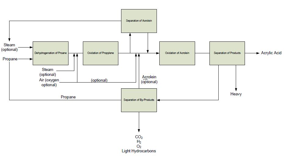
Block Flow Diagrams (BFDs) are the simplest forms of process diagrams, used in the early stages of a project to outline the major process flows and units. BFDs serve as the foundation for developing more detailed diagrams, like P&IDs, by providing a high-level overview of the process. They are created by process engineers and serve as a communication tool among various stakeholders (engineers, project managers, and clients) to establish a clear understanding of the process layout and flow.
BFDs feature blocks representing process units and arrows indicating the flow of materials or energy, without detailing the specific equipment or parameters. They are essential for conceptualizing and planning before delving into the complexities of Piping and Instrumentation Diagrams (P&IDs).
The Block Flow Diagram has the purpose of illustrating the logical flow of the processing phases of the product, highlighting the processing sequence, their concatenations, and the types of treatment plants: each block represents a treatment unit of the process plant.
Block Flow Diagrams (BFDs) are typically created by process engineers. These professionals use their understanding of the process system’s operation, including chemical reactions, physical transformations, and energy and material balances, to outline the major components and flow paths. The creation of BFDs is an integral part of the early design phases of a project, facilitating initial discussions, conceptual planning, and the basis for more detailed process design documents like PFDs (Process Flow Diagrams) and P&IDs (Piping and Instrumentation Diagrams).
The end-user (with their process consultants) may be involved in drafting BFD Diagrams, as a way to align the basic conceptualization of the system to be implemented.
PROCESS FLOW DIAGRAMS (“PFD”)
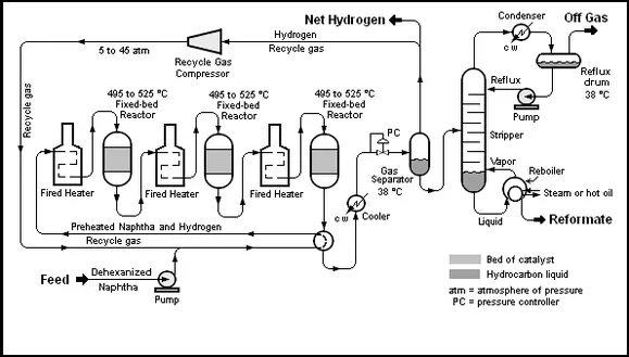
Process Flow Diagrams (PFDs) are detailed graphical representations used in chemical and process engineering to show the flow of chemicals and the equipment involved in the process. At this stage, engineers outline major components, such as reactors, heat exchangers, and separators, and the flow paths between them.
PFDs include information on temperature, pressure, flow rates, and composition of materials. They serve as a bridge between conceptual design and detailed engineering, laying the foundation for the development of Piping and Instrumentation Diagrams (P&IDs).
Here an example of a process flow diagram (PFD):

- Process Flow Diagram (PFD)
PROCESS AND INSTRUMENTATION DIAGRAM (“P&ID” OR P&I)
P&ID Definition
A Process and Instrumentation Diagram (P&ID) is a detailed diagram used in the process industry which shows the piping and process equipment together with the instrumentation and control devices needed to operate and control the plant.
P&IDs are the final result of the piping engineering design process which goes from BFD to PFD, and to P&ID.
Superordinate to the P&ID is the Process Flow Diagram (PFD) which indicates the more general flow of plant processes and the relationship between major equipment of a plant facility. P&IDs are used for the construction and maintenance of process facilities and show valves, sensors, and other control devices, providing a comprehensive overview of the operational process.
Who makes P&ID Diagrams?
P&IDs are created by process engineers who detail the mechanical and engineering aspects and by instrumentation and control engineers who specify and design the control system. This collaborative effort ensures that the diagram accurately reflects both the physical components of the system (like piping, equipment, and instruments) and how they are controlled during operation. The creation process involves reviewing PFDs, equipment specifications, and standards to ensure all elements are correctly represented and meet safety and operational requirements.
Each specialized engineering team implements, using an internationally recognized symbology (like, for example, ISA S series 5), the parts of its competence by drafting into the P&ID scheme information such as:
- Data and characteristics of the types of equipment
- Numbering and classification of pipes and other piping products
- Instrumentation in the control room
- Instrumentation and valves in the field
- Construction and installation notes
Tools to design P&ID
Tools used for creating P&ID diagrams range from basic drawing tools to advanced CAD and specialized software. Basic tools include manual drawing or general-purpose software like Microsoft Visio. For more complex projects, CAD software such as AutoCAD and specialized P&ID software like Bentley’s AutoPLANT, Intergraph’s SmartPlant P&ID, and Aveva’s Diagrams offer more sophisticated features.
These advanced tools support standards compliance and integration with other engineering systems, and offer libraries of symbols and components, streamlining the design process and enhancing collaboration among team members.
Learn more about the symbols used to make P&ID diagrams.
Typical content of P&ID Diagrams
In a P&ID, all components are numbered and defined in terms of service and specifications, nozzles, internals, and manholes are indicated, and the piping connection types are clearly defined.
More in detail, P&ID shows (with regards to piping components):
- any startup, production, shut-off, emergency, and maintenance line
- any piping component with explanatory comments
- process line information, such as line number, size, fluid symbol, applicable piping class, and insulation requirements
- any configuration requirement, like the number of pockets and free draining
Regarding instrumentation systems, P&ID drawings show:
- any instrument to control, monitor, shut down, interlock, or automate the plant
- all field instruments
- the control and shutdown valves including their type, failure status, and sizing information
- the required pressure relief valves with indications about the set over-pressure and sizing
- the types of signals, such as pneumatic, electric, hydraulic, soft links, digital, etc.
Lastly, P&ID diagrams should show:
- the battery limit between the EPC contractor and the End-User
- process packaged equipment
- line break information, such as line number, piping class, and insulation
P&ID Example
For a simple and complete P&ID see the image below: it shows a simple Wessel level control consisting of an electrical control loop (with level transmitter LT 1, level controller LIC 1, I/P converter LY 1, and level control valve LCV1), and an electrical safety loop (with a level switch of high-level LSHH 2 with level alarm LAHH 2 and safety valve LSV 2 auctioned by the solenoid S); in the diagram, the necessary different supplies, like air (AS), power (ES) and water (WS) are also shown.

- P&ID Diagram or P&I
Example of a measured and controlled Wessel with discrete electronic instrumentation
FLOW AND INSTRUMENTATION DIAGRAM (“F&ID” OR FID)
From the Piping & Instrumentation Diagram (P&ID), it is possible to obtain the Flow & Instrumentation Diagram (F&ID), which is also called “Scheme of March” that generally highlights:
- Process lines
- Main instrumentation
- Control and security loops
suitable for the construction of video pages and the management of the Distributed Control System (DCS).
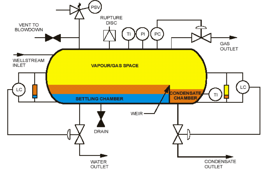
For a simplified F&ID see the image below which shows a typical 3-phase separator of crude oil coming from the extraction wells, in three phases:
- Gas, top right, controlled by the PC controller
- Oil, lower on the right, controlled by a first LC level controller
- Water, down on the left, controlled by a second LC level controller
Complete the control of the separator, and the safety devices to prevent high pressure:
- The Pressure Safety Valve (PSV)
- The Rupture Disk, normally named Pressure Safety Element (PSE)
The scheme is indeed simplified as a demonstration to present the main elements of:
- The measure, i.e. monitoring of the main process variables
- Regulation, or control of the main process variables
- Actuation, or modification of the main process variables
- Safety, control, and blocking of the process for exceeding the process pressure max
A simplified example of a 3-phase separator: Gas, Oil, and Water
DIFFERENCES BFD, PFD, P&ID
BFD VS. P&ID
BFDs (Block Flow Diagrams) provide a high-level overview of major process flows and unit operations using blocks, ideal for initial project conceptualization. They emphasize the sequence and interactions of major process steps without detailing the specifics of equipment or control systems. In contrast, P&IDs (Piping and Instrumentation Diagrams) offer detailed representations of the piping, equipment, and control systems in a process. P&IDs include specifics like pipe sizes, equipment details, and instrumentation symbols, essential for the design, operation, and maintenance of process facilities.
PFD VS. P&ID
PFDs (Process Flow Diagrams) depict the main flow of materials and energy in a process, including major equipment but not the detailed design. They show process conditions like temperature and pressure. A process flow diagram (PFD) shows, generally, only the major equipment used in a chemical process and the logical flow of the chemicals treated within the plant.
PFDs are developed in the initial stages of plant engineering, or for training, maintenance, and operation purposes, to outline the basic characteristics of the processes that have to be managed by the plant. A PFD generally does not show the relieving system, pump minimum flows, compressor anti-surge flows, and isolation system.
P&IDs (Piping and Instrumentation Diagrams), on the other hand, provide detailed mappings, including all pipes, valves, instruments, and control systems, necessary for the construction, operation, and maintenance of a process plant, showing the exact layout of all physical components.
A P&ID drawing represents the plant’s processes, including any major or minor flow, any piping and instrumentation equipment, and the control loops that govern the system.
P&ID diagrams are developed with the intense cooperation of instrumentation, electrical, mechanical, and safety engineers.


One Response
can you help me drawing the following Process Flow Diagram for a milk pasteurization plant.
Below is a simplified Process Flow Diagram for a milk pasteurization plant.
Add the missing instruments and the singals, then draw a Process and Instrumentation Diagrams (P&ID) for the above simplified milk pasteurization plant. Provide instrument tags according to ISA S5.1 standard.
Note that the process variable to be controlled here is the pateurized milk temperature.
Attach your drawing to your assignment.
You can use one of the following online services to create the diagram:
• https://app.diagrams.net
• https://www.lucidchart.com
When using the above services ensure that you add the “Process Engineering” symbols as shown below:
Diagrams.net
Lucidchart