Learn the basic terminology about steel pipes: dimensional concepts such as nominal pipe size (“NPS”), inside diameter (“ID”), wall thickness (“WT”), pipe schedule (“Sch.”), pipe length single/double random (“SRL”, “DRL”); finishing of pipe ends (“Plain”, “Bevelled”, “Threaded”); dimensional specifications (“Specifications”); material grades.
STEEL PIPES: KEY TERMINOLOGY
Understanding the terminology used to define the dimensions of steel pipes is crucial for engineers, fabricators, and industry professionals to ensure accurate specifications, compatibility, and performance in various applications.
DIMENSIONS OF STEEL PIPES
Here’s a glossary of key terms related to the dimensions of steel pipes:
Nominal Pipe Size (NPS)
“NPS” stands for Nominal Pipe Size, a standard used to designate the diameter of pipes. It is a nominal dimension system that doesn’t directly correlate to any specific measurement but serves as a reference that specifies the size of the pipe. The NPS system is widely used in the United States and internationally to standardize pipe sizes, making the specification, manufacturing, and procurement of pipes more systematic and efficient.
The significance of the NPS system lies in its ability to standardize pipe sizes across a wide range of industries, including plumbing, oil and gas, power generation, and construction. This standardization facilitates clearer communication and ensures compatibility of components, reducing errors and mismatches in the design and installation of piping systems.
Here’s how the NPS system works:
- For pipes with an NPS of 1/8 through 12, the NPS value roughly corresponds to the pipe’s inside diameter (ID) in inches. However, this correlation is not exact, and the outside diameter (OD) becomes the more consistent dimension to rely on, especially as sizes increase.
- For pipes with an NPS of 14 and above, the NPS value is equal to the outside diameter of the pipe measured in inches. For example, a pipe with an NPS of 14 has an outside diameter of 14 inches.
It’s important to note that the NPS does not directly indicate the physical dimensions of the pipe’s outside diameter or inside diameter. As the NPS number increases, the wall thickness of the pipe can vary significantly, especially when considering different schedule numbers (denoting wall thickness). Therefore, when specifying a pipe, both the NPS and the schedule number are critical to ensuring the correct pipe is selected for a specific application, considering factors such as flow rate, pressure, and structural integrity.
NPS is therefore a proxy measure of the internal flow capacity of the pipe (pipe bore capacity). The comparable European term for “NPS” is “DN” (i.e. “Diamètre nominal” or “Nominal diameter” and “Durchmesser Nach” in German – source: Wikipedia)
Outside Diameter (OD)
The “Outside Diameter” (OD) of a pipe is a critical dimension that refers to the total outer diameter of the pipe. It is a direct measurement from one outside edge to the opposite outside edge through the centerline of the pipe. The OD is an essential specification for pipes as it provides a clear and consistent reference for fitting, welding, and laying out pipelines, regardless of the wall thickness of the pipe.
Understanding the OD is crucial for several reasons:
- Compatibility with Fittings and Valves: The OD helps ensure that pipe fittings, valves, flanges, and other components match perfectly, ensuring a tight and leak-proof connection in the piping system.
- Standardization across Materials: The OD remains consistent across different pipe materials (steel, PVC, copper, etc.) for the same nominal pipe size (NPS), facilitating the interchangeability and integration of materials in complex systems.
- Installation and Support: Accurate OD measurements are vital for the proper installation of support structures, clamps, and brackets that hold the piping in place, ensuring stability and alignment throughout the system.
- Fabrication and Modification: For tasks such as cutting, bending, and welding, knowing the OD allows for precise modifications and customizations of the piping to fit the specific requirements of a project.
In the context of the NPS (Nominal Pipe Size) system, the OD becomes especially important for pipes with an NPS of 14 inches and larger, where the NPS directly corresponds to the pipe’s outside diameter in inches. For smaller sizes, the relationship between NPS and OD is not direct, but the OD still serves as a key dimension for design, specification, and installation processes in piping systems.

Inside Diameter (ID)
The “Inside Diameter” (ID) of a pipe refers to the internal diameter of the pipe, measuring the space through which fluid or gas flows. It’s a crucial dimension for engineers and designers because it directly affects the flow rate and pressure of the material moving through the pipe. The ID is determined by subtracting twice the wall thickness from the outside diameter (OD) of the pipe.
Understanding the ID is important for several reasons:
- Flow Capacity: The ID of a pipe influences the volume of fluid or gas that can pass through it in a given time, making it a key factor in calculating the pipe’s flow capacity.
- Pressure Loss: The size of the ID affects the velocity of the fluid and, consequently, the pressure loss due to friction between the fluid and the interior surface of the pipe. A smaller ID leads to higher velocity for a given flow rate, increasing pressure loss.
- Pump and Valve Sizing: Knowing the ID is essential for selecting the correct pump size and valve type to ensure they can handle the desired flow rate without causing excessive pressure loss.
- Compatibility with Inserted Devices: For applications involving the insertion of devices into the pipeline, such as sensors, probes, or cleaning tools, the ID must be large enough to accommodate these devices without obstructing flow.
The ID is not a fixed value for a given Nominal Pipe Size (NPS) because pipes with the same NPS can have different wall thicknesses, leading to varying IDs. This variability is accounted for by the pipe’s schedule number, which denotes the wall thickness. In practical terms, when the NPS and schedule number increase, the wall thickness typically increases, which can significantly alter the ID, even though the OD remains constant for a specific NPS.
In sum, the inside diameter (ID) of a pipe is a critical parameter in the design and operation of piping systems, affecting fluid dynamics, system capacity, and the overall efficiency and effectiveness of fluid transport.
Pipe with “Controlled ID”
A pipe with a “controlled inside diameter” (ID) refers to a pipe manufactured to have a precise internal diameter measurement. This specification is critical for applications where flow rate, pressure drop, and fluid velocity must be accurately calculated and controlled. The ID directly influences the pipe’s capacity to transport fluids or gases, making it a vital consideration for engineers and designers when selecting pipes for specific systems.
In many piping applications, the thickness of the pipe wall (and therefore the outside diameter, OD) can vary, while maintaining a specific inside diameter is crucial for the system’s performance. For example, in high-pressure applications, a thicker wall may be required to withstand the pressure, but the inside diameter must remain consistent to ensure a specific flow rate.
Pipes with controlled IDs are essential in scenarios where:
- Precise Flow Rates are necessary for process control within chemical, pharmaceutical, food processing, and other industrial applications.
- Hydraulic and Pneumatic Systems where pressure and flow dynamics are critical to the system’s operation and efficiency.
- Water Supply and Wastewater Management systems, where maintaining a specific volume and speed of flow is necessary for effective operation and regulatory compliance.
Manufacturing pipes with a controlled ID involves stringent production controls and quality assurance processes to ensure that the internal diameter meets the specified tolerances. This level of precision often requires advanced manufacturing techniques and materials, reflected in the pipe’s performance characteristics and cost.
Wall Thickness
Pipe wall thickness, denoted as “WT,” refers to the thickness of the pipe wall itself. This measurement is crucial for determining the strength, pressure rating, and durability of a pipe. Wall thickness directly influences a pipe’s ability to withstand internal pressures, external forces, and corrosive actions without failing or deforming.
The significance of WT in piping design and application includes:
1. Pressure Containment: Thicker walls allow a pipe to contain higher internal pressures. This is particularly important in applications involving the transport of fluids or gases under high pressure, such as in the oil and gas industry, chemical processing plants, and high-pressure steam systems.
2. Mechanical Strength: Increased wall thickness enhances the overall strength and rigidity of the pipe, making it more resistant to external impacts, ground pressure in buried applications, and bending stresses in unsupported sections.
3. Corrosion Allowance: In environments where corrosion is a concern, a thicker wall may be specified to ensure that the pipe maintains its integrity over its expected service life, even as the material is lost to corrosion.
4. Service Life: A thicker wall often translates to longer service life, especially in applications where wear and tear, erosion, or corrosion are expected. It provides a buffer against degradation, delaying the need for maintenance or replacement.
Wall thickness is specified according to the pipe’s schedule (for standardized thicknesses) or may be defined directly in millimeters or inches for custom applications. The schedule number (SCH) provides a standardized scale of wall thicknesses; common schedules include SCH 20, SCH 40, SCH 80, and SCH 160, with higher numbers indicating thicker walls.
When designing and selecting pipes for specific applications, engineers must balance the need for sufficient wall thickness to handle operational pressures and external conditions against considerations of cost, weight, and fluid resistance. Proper selection ensures the safety, efficiency, and longevity of the piping system.
Schedule Number (SCH)
A pipe schedule (SCH) is a standardized system used to denote the wall thickness of pipes. This concept is crucial in the pipe industry because it directly affects the pipe’s pressure rating, strength, and internal capacity. The schedule number is a key parameter that helps engineers, designers, and constructors specify and select pipes for various applications, ensuring that the pipes can handle the required pressure and flow conditions.
Understanding Pipe Schedule
- Wall Thickness and Schedule Number: The schedule number increases with the pipe’s wall thickness. Commonly used schedule numbers include SCH 20, SCH 40, SCH 80, SCH 160, etc., with SCH 40 being one of the most widely used for standard applications. Higher schedule numbers (e.g., SCH 80, SCH 160) indicate thicker walls, which can withstand higher pressures.
- Pressure Rating: The thicker the wall (higher schedule number), the higher the pressure the pipe can withstand. This makes the selection of the appropriate schedule critical for applications involving high-pressure fluids or gases.
- Diameter Consideration: The “pipe schedule system” takes into account the nominal pipe size (NPS). For a given NPS, the outer diameter (OD) remains constant, but the inner diameter (ID) decreases as the schedule number (and thus wall thickness) increases. This relationship is vital for calculating flow rates and pressure drops.
- Material Impact: The actual pressure rating for a given schedule also depends on the pipe material. Steel, stainless steel, PVC, and other materials have different strengths and thus will have different pressure ratings even for the same schedule number.
Application
The choice of pipe schedule is determined by several factors, including:
- Operating Pressure: Higher operating pressures require pipes with higher schedule numbers.
- Temperature Conditions: Elevated temperatures can affect material strength, potentially necessitating a thicker wall.
- Corrosion Considerations: Environments prone to corrosion may require thicker walls to ensure a longer service life, even if the pressure requirements are not as high.
- Cost and Weight: Higher schedule pipes, being thicker, are heavier and more costly. Balancing the need for pressure containment with cost considerations is a key aspect of piping system design.
In summary, the pipe schedule is a standardized method of specifying the wall thickness of pipes about their diameter, material, and intended use, playing a critical role in the safe and efficient design and operation of piping systems across various industries.
Pipe Length
The concept of pipe length, particularly in terms of single or double random lengths, is an important consideration in the distribution and installation of piping systems. These terms relate to the range of lengths in which pipes are manufactured and supplied, offering flexibility in usage and minimizing waste during installation.

Single Random Length (SRL)
- Definition: Single random-length pipes are those that are provided in a range of lengths, typically between 16 to 22 feet (4.9 to 6.7 meters), though the exact range can vary depending on the manufacturer or the standard being followed.
- Usage: SRL pipes are commonly used in various applications where the exact pipe length is not critical to the project’s requirements. This flexibility allows for efficient use of material with minimal waste, as pipes can be selected and cut to fit specific needs within a system.
Double Random Length (DRL)
- Definition: Double random length pipes are longer than single random lengths, with common ranges between 35 to 45 feet (10.7 to 13.7 meters), again subject to manufacturer’s specifications or relevant standards.
- Usage: DRL pipes are often used for large-scale projects or in situations where longer pipes reduce the number of required connections or joints, thereby minimizing potential leak points and enhancing the integrity of the piping system.
The term “random” refers to the fact that the pipe mill can control that the pipe length is between a min-max value, but cannot control the exact length of every single pipe (which will be variable, within the given range).
A double random-length pipe has an expected length twice the length of an SRL pipe.
Cut-to Length (CTL)
In this case, pipes are cut/trimmed at the manufacturing pipe mill to meet the specific requirements of a project. Utilizing custom dimensions may help reduce welding expenses during onsite assembly.
Choosing between SRL or DRL
1. Project Specifications: The choice between SRL and DRL pipes depends on project specifications, including the required pipe lengths, the nature of the fluid being transported, pressure requirements, and the installation environment.
2. Economic Factors: Using DRL pipes can reduce the number of couplings and fittings required, potentially lowering overall project costs. However, their longer lengths may increase transportation and handling challenges.
3. Welding and Fabrication: Fewer joints in a pipeline mean less welding and fabrication work, which can reduce labor costs and decrease the risk of leaks or failures at joint points.
4. Transportation and Handling: The logistics of transporting and handling longer DRL pipes may require special equipment or considerations due to their size and weight compared to SRL pipes.
In summary, the selection between single-random and double-random length pipes is influenced by various factors, including project requirements, cost considerations, and the practical aspects of pipe installation and maintenance. Understanding these options allows engineers and project managers to optimize their piping systems for safety, efficiency, and cost-effectiveness.
NPS vs. IPS Pipe System
The terms NPS (Nominal Pipe Size) and IPS (Iron Pipe Size) are often used in the context of pipe dimensions, but they can lead to some confusion because they are related yet distinct concepts in the piping industry. Understanding the difference between NPS and IPS is crucial for accurately specifying and working with pipe materials across various applications. Here’s a detailed explanation of both terms and how they relate to each other:
Nominal Pipe Size (NPS)
NPS is a standard used to designate the nominal diameters of pipes. It is based on a standardized scale of sizes that originally were based on the inner diameter (ID) measurements of wrought iron pipes. As piping technology evolved, including the introduction of different materials like PVC, stainless steel, and others, the NPS system became based more on the outside diameter (OD) of pipes. This standard is widely used in the United States and internationally for both pipes that convey fluids (such as water, oil, and gas) and structural applications.
- For pipes with an NPS of 12 inches and smaller, the NPS number does not directly correspond to any actual dimension of the pipe. It’s a nominal designation.
- For pipes with an NPS of 14 inches and larger, the NPS number is equal to the outside diameter (OD) of the pipe in inches.
The NPS system is used to specify the size of pipes in terms of nominal diameter, making it easier to standardize pipe sizes, fittings, valves, and other components across the industry.
Iron Pipe Size (IPS)
IPS was a standard for the dimensions of wrought iron pipe that predated the modern NPS system. It was used primarily for specifying the sizes of pipes made from iron. IPS dimensions were originally based on the inside diameter (ID) of a pipe, making it easier to match pipes with fittings since fittings are designed to fit on the inside of pipes. Over time, as different materials began to replace wrought iron and steel became the material of choice for pipe manufacturing, the IPS system evolved.
Today, the term IPS is sometimes used interchangeably with NPS because the size designations have become standardized around the NPS system. However, when the term IPS is used, it often refers to the original dimensions based on iron pipes, which might be important for historical context or when dealing with older piping systems that were specified using the IPS standard.
Key Differences NPS vs. IPS Pipe System
- Historical Context: IPS refers to an older system based on the internal dimensions of iron pipes, while NPS is a current standard that designates nominal pipe sizes based on a standardized scale, primarily reflecting the outside diameter for sizes 14 inches and above.
- Material Specificity: IPS was specific to iron pipes, whereas NPS is material agnostic and used across various materials, including steel, plastic, copper, and others.
- Usage: Today, NPS is the predominant system used in the piping industry for specifying the sizes of pipes, fittings, and valves. The term IPS may still be encountered, particularly in contexts involving older piping systems or specific industries that have continued using the term for traditional reasons.
In contemporary practice, NPS is the more relevant and universally accepted standard for pipe sizes, and understanding this system is essential for professionals in the piping, construction, and engineering fields.
STEEL PIPES FINISHING
Pipe Material Grade
The concept of “pipe material grade” refers to the classification of the material used to manufacture the pipe, based on its chemical composition and mechanical properties.
This classification is critical for ensuring that the pipe meets the specific requirements for its intended application, including strength, corrosion resistance, temperature tolerance, and compatibility with the fluids it will carry.
Material grades are defined by standards developed by organizations such as ASTM (American Society for Testing and Materials), API (American Petroleum Institute), and other international standards bodies.
Importance of Pipe Material Grade
- Mechanical Strength: Different applications require pipes that can withstand varying levels of stress, pressure, and mechanical impact. The material grade determines the pipe’s strength, ductility, and toughness, ensuring it can perform under the designed conditions without failure.
- Corrosion Resistance: Pipes are often exposed to corrosive substances, including water, chemicals, and gases. Certain material grades are specifically designed to resist corrosion, extending the lifespan of the piping system and reducing maintenance costs.
- Temperature Resistance: Depending on the application, pipes may need to operate under high or low temperatures. Material grades specify the temperature range within which the pipe material maintains its properties without degrading.
- Compatibility with Fluids: The pipe material mustn’t react adversely with the fluid it transports. Material grades help ensure compatibility, preventing contamination and material degradation.
Examples of common Pipe Material Grades:
- Carbon Steel: Grades like ASTM A106 Grade B are commonly used for high-temperature and pressure applications.
- Stainless Steel: Grades such as 304/304L and 316/316L offer varying levels of corrosion resistance, strength, and temperature tolerance, suitable for a wide range of applications.
- Alloy Steel: Grades like ASTM A335 P11, P22, and P91 are used for services that require higher temperature and pressure resistance.
- Duplex and Super Duplex Stainless Steel: These grades combine the properties of austenitic and ferritic stainless steels, offering high strength and corrosion resistance, used in harsh environments.
- Nickel Alloys: Grades such as Alloy 625 or Alloy 825 are used for their excellent corrosion resistance and strength at high temperatures, suitable for aggressive environments.
In reality, a multitude of material grades for pipes exist – both ferrous and non-ferrous. A possible taxonomy of material grades for pipes is shown in the picture below:
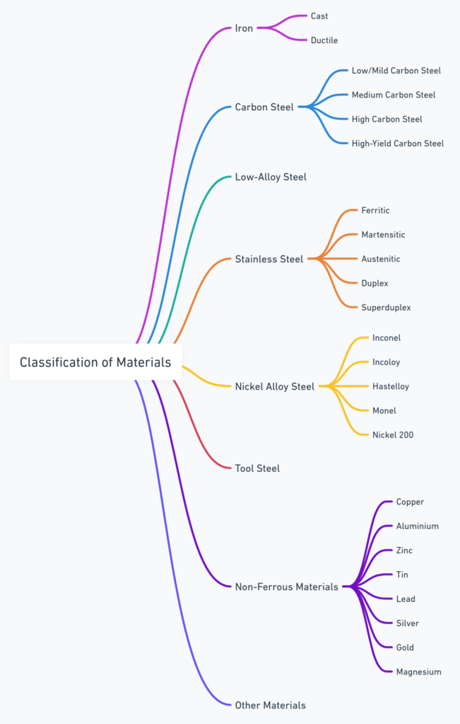
The specification of a pipe material grade involves considering the service environment, the physical and chemical properties required, regulatory standards, and cost. Proper selection based on these grades ensures the safety, reliability, and efficiency of the piping system across its intended lifespan.
Pipe Standards
Reference to the specific standards (e.g., ASTM, API, EN, BS) that the pipe conforms to. These standards dictate the manufacturing processes, material properties, dimensions, and tolerances.
Pipe End Finish
The concept of “pipe end finish” refers to the treatment or machining done to the ends of a pipe to prepare it for connection to other pipes, fittings, or equipment. The end finish is a critical aspect of pipe design and fabrication, affecting the ease of installation, the integrity of the joint, and, ultimately, the performance of the piping system. Different types of pipe end finishes are chosen based on the method of connection (welding, threading, flanging, etc.), the required seal quality, and the specific application’s demands.
Here are the main types of pipe end finishes and their applications:
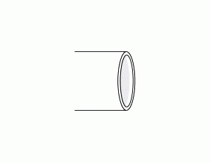
Plain End (PE)
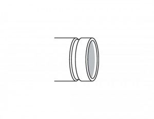
A plain end is a simple cut at the pipe’s end without any special treatment. This type of end finish is typically used where the connection will be made by welding, and no threading is necessary. It is common in larger-diameter pipes where butt-weld fittings are used.
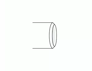
Beveled End (BE)
A beveled end is cut at an angle (typically 30 to 37.5 degrees) to the pipe’s longitudinal axis. This preparation is essential for butt welding, as it allows for proper weld penetration and a stronger weld joint. Beveled ends are standard for pipes that will be joined by welding in field installations and fabrication shops.
(Source: FTPipelineSystems)
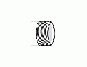
Threaded End (TE)
A threaded end is cut with threads on the outside (male) or inside (female) of the pipe. This finish allows for connection to other threaded components without welding. Threaded connections are common in smaller-diameter pipes and in applications where the piping system needs to be disassembled for maintenance or adjustment.
Grooved End
A grooved end features a groove cut into the end of the pipe. This finish is used with couplings that grip the groove to join pipes. Grooved end connections are quick and easy to assemble and are often used in fire protection systems, HVAC, and other applications where fast assembly or disassembly is beneficial.
Socket Weld End (SW)
A socket weld end is prepared for insertion into a recessed area or socket of a fitting, valve, or flange. The pipe is welded around its circumference to secure it in place. Socket weld ends are used in smaller diameter pipes and provide a strong joint that is less susceptible to leakage.
Threaded and Coupled (T&C) End
Threaded and Coupled (T&C) ends refer to a type of pipe end finish where the ends of the pipe are threaded (external threads are cut into the end of the pipe) and coupled (joined together with a coupling). The coupling is a short, cylindrical component with internal threads that match the pipe’s external threads. This allows two sections of pipe to be screwed together, forming a tight and secure connection.
T&C ends are commonly used in applications where it is necessary to assemble and disassemble the pipeline for maintenance, inspection, or modification. This method of connection eliminates the need for welding, making it convenient for applications where welding is not feasible or where rapid assembly and disassembly are required.
Key aspects of Threaded and Coupled (T&C) ends include:
- Ease of Installation: T&C connections can be quickly and easily made using hand tools, making them ideal for situations where rapid assembly or disassembly is beneficial.
- Versatility: This type of end finish is suitable for a wide range of applications, including water, gas, and oil pipelines, especially in low to medium-pressure systems.
- Sealing Integrity: When properly assembled with thread sealant or tape, T&C connections can be highly effective in preventing leaks, ensuring a secure seal.
- Maintenance and Repair: The ability to disassemble sections of pipe without cutting or welding is particularly advantageous for maintenance or repair work, allowing for easy replacement of damaged sections.
However, it’s important to note that threaded connections may not be suitable for all applications, especially those involving high pressure, corrosive fluids, or extreme temperatures, where welded connections might provide greater strength and reliability.
Bell End
A bell end has an enlarged diameter at one end, allowing the next section of pipe to be inserted into the bell. This finish is often found in PVC or other plastic pipes used in water and sewer applications, facilitating a simple, adhesive-based joining method.
Each type of pipe end finish is designed to meet specific requirements of the piping system, including the method of assembly, the need for disassembly, the operating conditions, and the overall design considerations. Selecting the appropriate end finish is crucial for ensuring the reliability, durability, and functionality of the piping network.

MECHANICAL PROPERTIES
Understanding the mechanical properties of pipe materials, including impact resistance, elongation, and tensile strength, is crucial for selecting the right pipe for specific applications. These properties determine how the material behaves under various loads, impacts, and stress conditions, directly influencing the safety, efficiency, and longevity of piping systems.
Impact Resistance
Impact resistance refers to a material’s ability to absorb energy and withstand shock loading without fracturing. It’s a critical property for pipes used in environments where they might be subjected to sudden impacts or cyclic loading conditions. Materials with high impact resistance are less likely to crack or fail abruptly. Impact resistance is typically measured by tests such as the Charpy V-notch test, which quantifies the energy absorbed by the material during fracture.
- High-Impact Resistance Materials: Ductile iron, certain grades of carbon steel, and high-impact grades of thermoplastics (such as HDPE) are known for their excellent impact resistance.
- Low Impact Resistance Materials: Some grades of cast iron and hardened steels, although very strong, can be brittle and more susceptible to cracking upon impact.
Hardness
Hardness is the measure of a material’s resistance to deformation, especially permanent deformation, indentation, or scratching. Hardness tests, such as the Brinell, Rockwell, and Vickers tests, apply a specific force to a hard indenter, and the size or depth of the resulting indentation is measured. Hard materials are often wear-resistant and capable of retaining a sharp edge, making hardness a critical property in tools and wear surfaces.
Toughness
Toughness is the ability of a material to absorb energy and plastically deform without fracturing. It’s a measure of the material’s resistance to cracking under stress and combines both strength and ductility. Materials with high toughness can withstand impact and shock loads without breaking. Toughness is assessed by impact tests, such as the Charpy or Izod tests, which measure the energy absorbed by a material upon impact.
Elongation
Elongation is a measure of ductility, indicating how much a material can stretch or deform before breaking. It’s expressed as a percentage of the original length after fracture. High elongation values suggest that the material can undergo significant deformation, allowing it to absorb energy and yield under stress rather than breaking suddenly. This property is particularly important in applications where pipes may experience stretching or bending forces.
- High Elongation Materials: Austenitic stainless steels (such as 304 and 316) and aluminum alloys typically exhibit high elongation, indicating good ductility.
- Low Elongation Materials: Brittle materials like cast iron show low elongation, meaning they are more likely to fracture than deform under stress.
Tensile Strength
Tensile strength is the maximum stress that a material can withstand while being stretched or pulled before failing or breaking. It is a fundamental indicator of a material’s mechanical strength. High-tensile strength materials are capable of supporting significant loads without failing, making them suitable for high-pressure applications.
- High Tensile Strength Materials: Alloy steels, certain grades of stainless steel (such as 316), and titanium alloys offer high tensile strength, making them ideal for high-pressure and high-strength applications.
- Lower Tensile Strength Materials: Some plastics and cast iron have lower tensile strengths, but may still be suitable for applications where lower pressures are involved or where other properties (like corrosion resistance) are more critical.
Ultimate Tensile Strength (UTS)
Ultimate Tensile Strength (UTS) is the maximum stress a material can withstand while being stretched or pulled before necking, which is when the specimen’s cross-sectional area starts to significantly decrease. UTS is a measure of the maximum load a material can support without failure and is typically measured in megapascals (MPa) or pounds per square inch (psi). It’s an essential factor in determining a material’s suitability for structural applications where it will experience tensile loads.
Difference Between Ultimate Tensile Strength and Tensile Strength
The terms “ultimate tensile strength” (UTS) and “tensile strength” are often used interchangeably in engineering and materials science, but they can have slightly different implications depending on the context:
Ultimate Tensile Strength (UTS)
Ultimate Tensile Strength is the maximum stress that a material can withstand while being stretched or pulled before failing or breaking. It represents the peak point on the stress-strain curve that occurs just before the material starts to neck (a local reduction in cross-sectional area, leading to failure). UTS is a critical property for understanding a material’s mechanical strength and is measured in units of force per area, such as megapascals (MPa) or pounds per square inch (psi).
Tensile Strength
In a broader context, “tensile strength” can sometimes refer to the strength of a material under tension in general, without specifying a particular point on the stress-strain curve. However, in most cases, when people refer to tensile strength, they are specifically talking about the ultimate tensile strength. That said, the term “tensile strength” might also be used to discuss other points of interest on the stress-strain curve, such as:
- Yield Strength: The stress at which a material begins to deform plastically (permanently). Before reaching the yield point, the material will deform elastically and return to its original shape when the applied stress is removed.
- Breaking Strength: Sometimes, particularly in the context of ropes, cables, and textiles, “tensile strength” might refer to the breaking strength, which is the stress at which the material ultimately fails and breaks. This can be similar to or the same as the UTS, depending on the material’s ductility.
Key Differences
- Specificity: UTS is a specific value indicating the maximum stress a material can sustain in tension before failure. Tensile strength, when used without qualification, can be a more general term referring to a material’s resistance to tension but is most commonly synonymous with UTS.
- Context and Application: The significance of UTS is universal in material science and engineering, providing a clear, quantifiable measure of a material’s maximum load-bearing capacity in tension. “Tensile strength” might sometimes be used in a more general sense or refer to other specific tensile properties depending on the context.
Yield Strength
Yield strength is the amount of stress at which a material begins to deform plastically. Before reaching the yield point, the material will deform elastically and return to its original shape when the applied stress is removed. Once the yield point is passed, some degree of permanent deformation will occur, and this is considered the end of elastic behavior and the beginning of plastic behavior. Yield strength is critical for engineering and design, as it indicates the maximum stress that can be applied without causing permanent deformation.
Elasticity
Elasticity is a material’s ability to return to its original shape after the stress causing the deformation has been removed. This property is governed by Hooke’s Law for small deformations, where the stress is directly proportional to the strain. Materials with high elasticity are less likely to be permanently deformed under load. The modulus of elasticity, or Young’s modulus, is a quantitative measure of a material’s elastic behavior under tension or compression.
Creep Resistance
Creep resistance is the ability of a material to resist deformation under sustained stress over an extended period, especially at high temperatures. Creep is a time-dependent deformation that typically occurs at temperatures above approximately 40% of the material’s absolute melting temperature (on a Kelvin scale). Materials with high creep resistance are essential in high-temperature applications like turbine blades and nuclear reactors.
Fatigue Resistance
Fatigue resistance is the ability of a material to withstand cyclic loading, the repeated application of stress or strain over time. Fatigue can lead to material failure at stress levels lower than a material’s ultimate tensile strength if subjected to enough cycles. Materials with high fatigue resistance are crucial in applications where components are subject to frequent or cyclic loading, such as bridges, aircraft, and rotating machinery.
Selecting pipe materials based on their mechanical properties ensures that the piping system can handle the operational demands of specific applications. High impact resistance prevents sudden failure from shocks, high elongation allows for some deformation under stress, providing a safety margin before failure, and high tensile strength ensures the pipe can withstand internal pressures and loads. Balancing these properties, along with other factors such as corrosion resistance and temperature tolerance, allows engineers to design safe, reliable, and efficient piping systems.

12 Responses
the best product more details for mantion in this link
With the help of this article I have understood the various lengths of Stainless Steel Pipes. I have also learnt about the various lengths of pipes and pipe end types. Thank you for sharing all this information with us.
I see your blog it’s useful….
Piping length matters a lot for any kind of residential or commercial requirement & the differences can make sure you get the material you want in the size you need. These comprehensive comparative tips are really helpful for our industries. I would appreciate the effort that you have mentioned in the blog. Keep posting.
I didn’t realize that the length of the pipe were related to the diameter of the pipe. My father is looking for a pipe that is over 11 meters long. I will have to let him know that he should look for pipes that are over 2 inches in diameter.
When using 2” pipe, do you have to put a bevel on it? Or does it come beveled or threaded (typically) when used in oil/gas?
I look for pipe The diameter of the pipe is 2 meters, the length is 12 meters, and the thickness is 12 mm ….10mm & 8mm
Hello,Hesham , Pls send your inquiry to email address :leo@abtersteel.com
useful post and data, Thank you.
Thank you for your appreciated comment. Should you need further information on some specific topics, kindly send us an email to support@projectmaterials.com. To submit an RFQ for piping materials, please visit this page: https://projectmaterials.com/submit-rfq-mto. Best regards, Projectmaterials
I read your blog. It’s a very useful. thanks for sharing useful information with us.
http://siddhipipe.com/
Fine waay of explaining, and good article too take facts
concerning my presentation subject matter, which i am goinng to delkiver in institution of higyer
education.