
VALVE KEY COMPONENTS
BODY
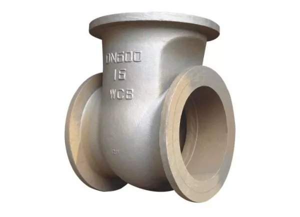
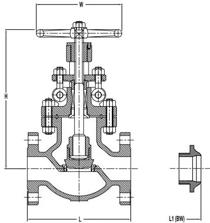
In the oil and gas industry, a valve body is the primary and critical component of a valve, functioning as the main structure that holds the valve together and contains the fluid flow. Made from materials capable of withstanding the harsh conditions and substances found in oil and gas applications, the valve body is engineered to handle high pressures, corrosive materials, and extreme temperatures. The body holds in position the moving components in contact with the fluid and has to withstand the pressure existing in the piping system.
Valve bodies in the oil and gas sector are typically constructed from robust materials such as carbon steel, stainless steel, alloy steels, and sometimes special alloys like Inconel, Monel, and Hastelloy. The choice of material depends on the specific application’s demands, including the type of fluid (oil, gas, water, etc.), temperature, pressure, and potential corrosive interactions. For instance, stainless steel and special alloys are preferred in environments where corrosion resistance is paramount.
The body can be manufactured by casting or forging steel in a variety of shapes, designs, and grades.
In the oil and gas industry, the most common materials for cast bodies are ASTM A216 and ASTM A105 for forged bodies (high-temperature service). For low-temperature service, ASTM A352 LCB/LCB and ASTM A350 LF2/LF3 are used, respectively, for cast and forged bodies.
As the temperature, the pressure, or the corrosion increase, stainless steel bodies become necessary: ASTM A351 CF8 (SS304) and CF8M (SS316) for cast devices, and the various ASTM A182 Fxx (F304, F316, F321, F347) for forged types.
For specific applications, special material grades with even stronger corrosion resistance are used, such as super austenitic stainless steels (SMO 254), duplex and super duplex steels (F44, F51, F53, F55), and nickel alloys (Inconel, Incoloy, Hastelloy).
For marine applications, non-ferrous materials or alloys are the elective choices, like Monel, Cupronickel, Aluminum-bronze alloys, and other alloys combining Nickel, Copper, and Aluminium. Cast iron bodies, which are the cheapest types, are used for water distribution (low-pressure applications).
The design of a valve body encompasses several key features:
- Connections: Valve bodies are designed with various end connections to facilitate integration into piping systems. These connections can be flanged, threaded, welded, or socket welded, each suitable for different applications and pressure ratings.
- Pressure Containment: The valve body is engineered to contain the operational pressures of the fluid it controls without leakage. Its thickness and material composition are calculated to withstand the maximum expected pressure and any thermal expansions.
- Flow Path: Inside the valve body is the flow path, which can be straight-through or angular, determining the direction and characteristics of the fluid flow. The internal design, including cavities and ports, is optimized for minimal flow resistance and efficient operation.
The valve body houses several integral components crucial for valve operation, including:
- Trim: The internal parts that come in direct contact with the fluid, such as the disc, seat, and stem. The trim regulates the flow and sealing within the valve.
- Bonnet: The component that attaches to the valve body to enclose the internal parts. It can be bolted, screwed, or welded to the body.
- Packing: A sealing system within the valve body that prevents fluid leakage around the stem.
In the oil and gas industry, the reliability and safety of operations heavily depend on the quality and integrity of valves. Valve bodies are therefore designed to meet stringent industry standards and certifications, such as API (American Petroleum Institute) and ASME (American Society of Mechanical Engineers), to ensure they can handle the demanding operational conditions. Their role in controlling the flow, pressure, and direction of petroleum products, natural gas, and by-products makes them indispensable components in exploration, production, refining, and distribution processes.
Body End Connections
Valves can be connected to other mechanical devices and pipes in different ways. The main end types are flanged and buttweld (for devices above 2 inches) and socket weld or threaded/screwed (NPT or BSP) for small-diameter devices. Butterfly valves have more articulated body-end types, like lug, wafer, and double-flanged ends.
Let’s now delve into the different types of valve bodies’s end types:
Flanged Ends

In this case, the device has two flanged ends that can be connected with a pipe by using a mating (companion) flange.
A flanged connection requires a proper number of stud bolts and nuts, as indicated by the ASME B16.5 specification, and a suitable gasket.
Flanged connections are common for larger-diameter valves, and they ensure long-lasting, and strong, joints.
The flange face may be raised, flat, ring joint, tongue, and groove male & female (the most common finish is the RF type, i.e. raised face), and be finished in any of the available variants (stock, serrated or smooth).
Socket Weld and Buttweld


Valves with socket weld ASME B16.11 or buttweld ends ASME B16.25 are welded to the connecting pipe.
Buttweld connections require full welding of the beveled ends of the two parts to be joined, whereas socket weld connections are made by fillet welds.
Threaded End Connections

BSP VS. NPT Threaded Connections
BSP (British Standard Pipe) and NPT (National Pipe Thread) are two of the most commonly used threaded connections for pipes and fittings, especially in the context of connecting valves, instruments, and plumbing components. Despite serving similar functions in creating secure threaded connections for fluid transport systems, they differ significantly in design, application, and compatibility. Understanding these differences is crucial for ensuring leak-proof and efficient piping systems, particularly in industries like oil and gas, water management, and manufacturing.
Design Differences between BSP and NPT threaded-ends:
- Thread Form: NPT threads have a 60-degree thread angle with a tapered profile, which means the diameter of the threads increases or decreases along the length of the fitting. This taper creates a seal through the wedging action of the threads themselves, often requiring thread sealant or tape to ensure a leak-proof connection. In contrast, BSP threads come in two types: BSP Parallel (BSPP), with a straight or parallel thread profile, and BSP Tapered (BSPT), with a taper similar to NPT but with a 55-degree thread angle. The different angles and shapes affect how each thread type seals and mates with its counterpart.
- Sealing Mechanism: NPT fittings rely on the interference fit between the male and female threads for sealing, necessitating the use of a sealant. BSPP connections, however, usually require a bonded seal or washer placed between the male and female ends for a leak-free seal, while BSPT connections can seal on the thread itself like NPT, though the thread profiles are not interchangeable.
Application and Compatibility:
- Geographical Use: NPT is the standard thread type in the United States and Canada for connecting pipes and fittings in pneumatic, hydraulic, and plumbing systems. BSP threads are more common in Europe, Asia, Australia, and other parts of the world. While both types are used globally, their prevalence varies by region, influencing their selection based on local standards and availability.
- Interchangeability: Due to their different thread angles and designs, NPT and BSP fittings are not directly interchangeable. Attempting to mate an NPT fitting with a BSP counterpart can result in damage to the threads, inadequate sealing, and potential leaks. Special adapters are required to connect NPT and BSP threaded components securely.
Choosing Between BSP and NPT:
Selecting between BSP and NPT threads depends on several factors:
- Regional Standards and Availability: Choose the thread type that aligns with the local standards and is readily available in your region to ensure compatibility with existing systems and ease of replacement.
- Application Requirements: Consider the specific requirements of your application, including the type of fluid, pressure, and the need for a reliable seal. For example, BSPP might be preferred for applications requiring a flat sealing surface, while NPT and BSPT are better suited for creating tighter seals in high-pressure systems.
- System Design: The overall design of your piping or fluid transport system may dictate the choice of thread type, based on the connections used in existing components and the need for adapters or specific sealing methods.
Understanding the distinctions between BSP and NPT threaded connections is essential for engineers, plumbers, and technicians to make informed choices when designing and assembling piping systems. Proper selection and installation not only ensure system integrity and leak-free operation but also compliance with regional standards and practices.
VALVE BONNET
The valve bonnet is a critical component of a valve assembly, serving as the cover for the valve body. It is second in importance only to the valve body itself in the overall valve structure. The bonnet is attached to the valve body, which is the primary pressure-containing structure, and together, they enclose the internal parts of the valve that come into direct contact with the process fluid, such as the stem, disk, and seat. Let’s explore the functions, types, and significance of the valve bonnet in more detail:
Functions of the Valve Bonnet
- Pressure Containment: The bonnet acts as a seal, ensuring that the process fluid does not escape from the valve body. It is designed to withstand the maximum pressure of the valve’s intended use.
- Component Protection: By enclosing the internal parts of the valve, the bonnet protects them from external contaminants and damage, contributing to the valve’s durability and reliability.
- Access Point: The bonnet can serve as an access point for the maintenance, repair, or replacement of the valve’s internal components. Depending on the valve design, removing the bonnet may provide direct access to the internals.
Types of Valve Bonnets
Valve bonnets come in various designs, each suited to different applications and pressure conditions. Common types include:
- Bolted Bonnet: A widely used design where the bonnet is attached to the valve body with bolts or studs and nuts. It provides a sturdy seal and is suitable for a broad range of pressures and temperatures.
- Screwed Bonnet: In this design, the bonnet is screwed directly into the valve body. Screwed bonnets are commonly used in smaller valves and lower-pressure applications.
- Welded Bonnet: For valves used in high-pressure and high-temperature applications, a welded bonnet provides a leak-proof seal by permanently welding the bonnet to the valve body. This design is often used when the valve does not require regular maintenance.
- Pressure Seal Bonnet: Used in high-pressure applications, this design employs a gasket that is pressure-energized to enhance the seal between the bonnet and the valve body as the internal pressure increases.
- Union Bonnet: A design that allows for easy disassembly and reassembly of the valve for maintenance. The bonnet and body are connected with a threaded union, facilitating straightforward access to the valve internals.
Significance of the Valve Bonnet
The valve bonnet plays a vital role in ensuring the safe and efficient operation of the valve. Its design and construction are critical for maintaining the integrity of the valve under operating conditions. Choosing the appropriate bonnet type based on the specific requirements of the application, such as pressure, temperature, and the need for maintenance access, is essential for valve performance and longevity.
In summary, the valve bonnet is an indispensable part of the valve assembly, contributing to pressure containment, protection of internal components, and, depending on its design, facilitating maintenance and repair activities. Its importance in the overall functionality and safety of the valve system cannot be overstated.
TRIM
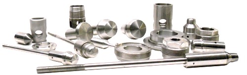
The trim is a collective name for all the internal parts of the valve that can be removed and replaced (these parts are also called “wet”, as they are in direct contact with the conveyed fluid).
Typically, the trim includes components such as the disc, the seat, the stem, the glands, the bushings, and the sleeves needed to guide the stem (the actual list of components that make up the trim depends, actually, on the type of device).
Valve trim refers to the internal components of a valve that come into direct contact with the fluid being controlled. It plays a crucial role in the function and performance of the valve, affecting its ability to regulate flow, pressure, and temperature within a system. The trim essentially determines how the valve operates, including how it opens and closes, and how it modulates or throttles the flow of the process medium. Understanding the components that make up the valve trim and their functions is essential for selecting the right valve for specific applications and ensuring optimal performance and durability.
Components of Valve Trim
The main components of valve trim include:
- Disc or Ball: The component that actually blocks the flow path or allows flow through the valve. In globe and gate valves, this is typically a disc; in ball valves, it’s a ball with a hole through the center.
- Seat: The seat provides a sealing surface for the disc or ball to rest against when the valve is closed. The quality and material of the seat are crucial for ensuring a tight seal and preventing leakage.
- Stem: The stem connects the actuator or handle to the disc or ball and transmits the motion required to open or close the valve. It can move linearly (in globe or gate valves) or rotate (in ball or butterfly valves).
- Cage: In some valve designs, particularly in globe valves, the cage surrounds the disc and can guide its movement as well as provide additional flow control and stability.
- Spring: Springs may be used in some valve trims, particularly in check valves and safety valves, to provide the necessary force for opening or closing the valve under certain conditions.
- Plug: In some types of valves, like plug or globe valves, a plug may serve as the obstructing element instead of a disc or ball.
Importance of Valve Trim
- Flow Control: The design and material of the valve trim directly influence the valve’s ability to control the flow rate, direction, and pressure drop across the valve. Different trim designs cater to different control needs, from simple on/off to precise flow regulation.
- Durability and Wear Resistance: The trim components are subject to continuous wear due to their contact with the process fluid. Selecting trim materials that are compatible with the fluid and operating conditions (such as temperature and pressure) is essential to ensure the valve’s longevity and reliability.
- Maintenance and Replacement: Over time, parts of the valve trim may need maintenance or replacement due to wear or damage. The design of the trim affects the ease with which these maintenance activities can be carried out. Modular trim designs allow for easier replacement of worn components.
Selecting the Right Valve Trim
Choosing the appropriate valve trim requires careful consideration of several factors, including the nature of the fluid (its corrosiveness, viscosity, and presence of solids), the required flow control characteristics, and the operating conditions (pressure and temperature). The right trim material and design ensure that the valve performs effectively and efficiently over its intended lifespan, minimizing maintenance needs and operational downtime.
Typical trim combinations for gate, globe, and check valves have been standardized by the API trim chart.
In summary, valve trim is the collective term for the internal components of a valve that interact with the fluid being controlled. Its design and material composition are critical for ensuring the valve’s effective operation, durability, and ability to meet specific flow control requirements.
DISC
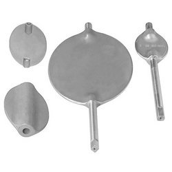
The valve disc is a fundamental component within the valve trim, playing a critical role in the valve’s function of regulating, stopping, or starting the flow of fluid.
It interacts directly with the fluid path, and its movement—either towards or away from the valve seat—controls the flow through the valve. The design, material, and proper functioning of the valve disc are vital for ensuring the valve’s effectiveness and reliability in various applications, ranging from simple water piping systems to complex chemical processing plants.
Functionality of the Valve Disc
- Flow Regulation: The primary function of the valve disc is to regulate the flow of fluid through the valve. By moving closer to or further from the valve seat, the disc alters the size of the opening through which the fluid can pass, thereby controlling the flow rate.
- Sealing: When fully engaged with the seat, the disc provides a tight seal that prevents fluid from passing through the valve, achieving a complete shutoff. The efficiency of this seal is crucial for preventing leaks and ensuring the safety and efficiency of the system.
- Modulation: In some valve types, such as globe or control valves, the disc can be positioned to precisely control the flow rate, allowing for fine modulation of the process fluid. This capability is essential in applications where maintaining specific flow parameters is critical.
Types of Valve Discs
The specific design of a valve disc can vary depending on the type of valve and its intended application. Common types include:
- Flat Discs: Used in gate valves, flat discs move vertically to the flow direction, providing an on/off function by either completely blocking or allowing flow.
- Ball Discs: In ball valves, the disc is a sphere with a hole through its center. Rotation of the ball opens or closes the flow path, offering both shutoff and throttling capabilities.
- Plug Discs: Utilized in plug valves, these discs are cylindrical or conically tapered plugs that rotate to control flow through an opening in the plug.
- Butterfly Discs: Butterfly valves use a flat, circular disc that pivots in the center of the valve body. This design allows for quick operation and is used for both isolation and flow regulation.
Material Considerations
The material of the valve disc is selected based on the fluid characteristics (such as corrosiveness, temperature, and pressure), the valve’s application, and the desired longevity. Common materials include:
- Metals: Stainless steel, carbon steel, brass, and bronze are widely used for their strength, durability, and resistance to high temperatures and pressures.
- Plastics: For applications involving corrosive fluids or lower pressure and temperature conditions, plastics such as PVC, PTFE (Teflon), and PVDF offer excellent corrosion resistance and reduced cost.
- Ceramics: Employed in applications involving abrasive fluids, ceramic discs provide superior wear resistance.
Significance of the disc for valves’s performance
The valve disc is a pivotal component within the valve’s architecture, instrumental in controlling fluid flow, ensuring tight shutoff, and enabling precise flow modulation. Its design, material, and compatibility with the valve seat are critical for the valve’s performance, efficiency, and durability in various industrial and residential applications. Selecting the right valve disc requires a thorough understanding of the application requirements, including the fluid’s nature, operational conditions, and desired control characteristics.
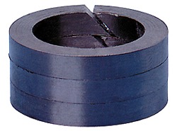
SEATS
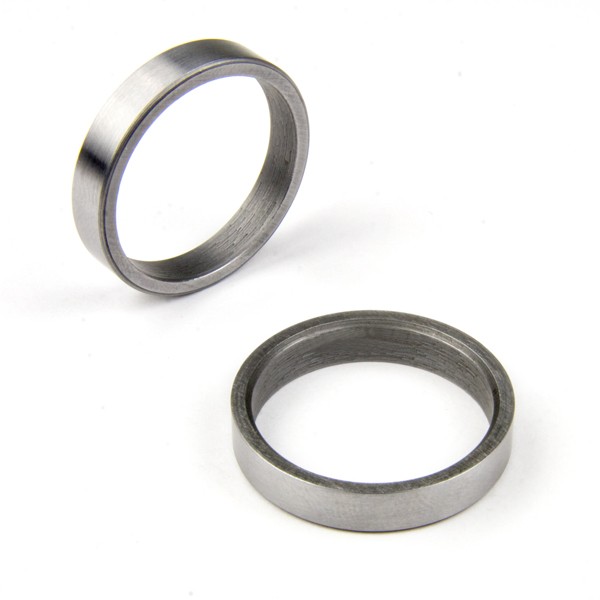
Valve seats are integral components of a valve’s internal mechanism, designed to interface with the valve disc (or plug, ball, etc.) to form a tight seal that controls or stops fluid flow through the valve.
These seats play a pivotal role in ensuring the efficiency, reliability, and leakage prevention of the valve during operation. The material composition, design, and condition of the valve seats are critical to the valve’s performance, affecting its ability to regulate flow accurately and maintain a secure seal under various operating conditions.
Function and Importance
- Sealing Surface: The primary function of a valve seat is to provide a smooth, precise surface for the valve disc to rest against, creating a seal that prevents fluid from leaking past the closed valve.
- Flow Regulation: In valves designed for throttling, the seat works in conjunction with the disc to modulate the flow of fluid. The design of the seat can influence flow characteristics and control precision.
- Durability and Wear Resistance: Valve seats must withstand continuous contact with the valve disc and resist wear and deformation from the process fluid, pressure fluctuations, and mechanical operations.
Seats Materials
Valve seats are made from a variety of materials, chosen based on the application’s specific requirements, including the type of fluid, operating pressure, temperature, and corrosive potential. Common materials include:
- Metals: Stainless steel, bronze, and brass are commonly used for their durability and resistance to high temperatures and pressures. Hardened metals or alloys may be used in severe service conditions for enhanced wear resistance.
- Soft Seats: Materials such as PTFE (Teflon), nylon, and other elastomers offer excellent sealing capabilities and resistance to chemical corrosion. Soft seats are used in applications where metal seats might not provide an adequate seal, but they are generally limited to lower temperature and pressure conditions.
- Ceramics: For high-wear or corrosive applications, ceramic seats offer superior hardness, wear resistance, and stability under extreme temperatures.
Design Considerations
The design of the valve seat is crucial for its function and longevity. Factors to consider include:
- Seat Shape and Angle: The contour and angle of the seat affect the sealing efficiency and flow characteristics. Seats can be designed for linear or equal percentage flow characteristics in control valve applications.
- Interchangeability: Some valve designs feature replaceable seats, allowing for easy maintenance and extended valve life. These seats can be swapped out when worn or damaged without replacing the entire valve.
- Sealing Method: The seat-to-disc contact area and method of sealing (e.g., metal-to-metal, soft seal) determine the tightness of the seal and the valve’s suitability for specific applications.
Special treatments for valve seats
Valve seats are integral components of valve assemblies, providing a sealing surface against which the valve disc or plug seals to stop the flow of fluid. The performance and longevity of a valve largely depend on the condition and material of the valve seat, as it must withstand the mechanical stresses and corrosion caused by the flowing medium. To enhance their durability, wear resistance, and sealing capabilities, valve seats may undergo various special treatments. These treatments are designed to ensure that the valve operates reliably over its intended lifespan, even under harsh operating conditions. Here are some common treatments available for valve seats:
Hardening Treatments
- Surface Hardening: Processes like induction hardening and flame hardening increase the surface hardness of the seat, improving wear resistance without compromising the toughness of the base material.
- Case Hardening: Techniques such as carburizing, nitriding, and carbonitriding add a hard, wear-resistant layer to the surface of the seat while maintaining a ductile interior. These treatments are particularly useful for seats in valves handling abrasive particles.
Coating Treatments
- Stellite Overlay: Stellite, a cobalt-chromium alloy, is known for its excellent hardness and resistance to wear and corrosion. Applying a Stellite overlay on valve seats can significantly extend their service life, especially in high-pressure, high-temperature, and erosive applications.
- Chrome Plating: Chromium plating offers good wear resistance and low friction, making it suitable for valve seats in applications where minimizing leakage is critical.
- Nickel Alloy Coatings: Nickel-based coatings, including Inconel and Monel, provide enhanced corrosion resistance in environments with corrosive fluids or gases.
- Thermal Spray Coatings: Techniques like High-Velocity Oxygen Fuel (HVOF) spraying can apply tungsten carbide or other hard materials onto the seat surface, improving wear and corrosion resistance.
Material Upgrades
- Solid Seats: In some cases, the entire seat is made from a high-performance material, such as ceramics or high-nickel alloys, to withstand extreme conditions of temperature, pressure, and corrosion.
- Inserts: Using inserts made from durable materials like ceramics or hardened metals can offer superior wear and corrosion resistance. These inserts are either pressed or screwed into the valve body.
Lapping and Grinding
- Precision Lapping: This process involves rubbing the seat against a flat surface with an abrasive compound to achieve a high degree of surface finish and flatness. Lapping ensures a tight seal between the seat and the disc or plug.
- Grinding: Grinding processes can be used to restore damaged or worn seats, improving the sealing surface’s condition and extending the valve’s operational life.
Each treatment has its specific advantages and is chosen based on the valve’s application, the characteristics of the fluid it controls, and the operating conditions (pressure, temperature, and presence of abrasive particles). By selecting the appropriate treatment for valve seats, manufacturers and users can ensure optimal performance, reduce maintenance costs, and extend the lifespan of valves in various industrial and commercial applications.
Importance of valve seats
Valve seats are crucial for the functionality and performance of valves, acting as the sealing interface that regulates fluid flow and ensures leak-free operation. The selection of seat material and design is tailored to the valve’s intended use, considering factors such as fluid compatibility, pressure and temperature conditions, and required flow control characteristics. Proper maintenance and timely replacement of valve seats are essential for maintaining optimal valve performance and system integrity.
STEM
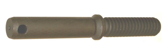
For the gate and globe types, the stem operates a linear motion on the disc, whereas, for the ball, butterfly, and plug types, the disc rotates to open or close the device (“quarter turn valves”).
Stems are made of forged steel and are connected to the disc by threading or other means. A proper finish of the stem surface is necessary to prevent leakages.
There are five main types of stems:
- Rotary: This is a standard type of ball, plug, and butterfly valve. A quarter-turn motion of the stem is needed to open/close the device
- Sliding: In this case, the stem does not execute any rotation. The stem slides in and out the valve to open or close it. This design is common in hand-operated lever rapid-opening valves. It is also used in control valves are operated by hydraulic or pneumatic cylinders.
- Rising type with outside screw and yoke (“OS&Y”): the external side of the stem is threaded while the part of the stem which is inside the valve is plain. The threads of the stem are isolated from the medium by the packing. Two alternative designs are available. The “OS&Y” design is common for valves above 2″.
- Rising type with an inside screw (“IS&Y”): The threaded part of the stem is positioned inside the valve body, whereas the stem packing lays outside. With this design, the stem threads are in touch with the medium flowing through the pipeline. Once rotated, the stem and the hand wheel rise together and open the valve.
- Non-rising stem type with inside screw: The threaded part of the stem is inside the valve and does not rise. The valve disc floats on the stem, like a nut if the stem is rotated. Stem threads are in contact with the media of the pipeline, and as such, may be exposed to its corrosive impact. This is the reason why such a design is used when the available space to position the valve is too narrow to permit linear movement, and the media does not cause erosion, corrosion, or abrasion of the stem material.
PACKING
The gasket that seals the stem with the bonnet is called packing and comprises the following components:
- Gland follower, which is a sleeve that compresses the packing, by a gland into the stuffing box.
- Gland is a type of bushing, which compresses the packing into the stuffing box.
- A stuffing box is a chamber in which the packing gets compressed.
- Packing is available in different materials, like PTFE, elastomers, fibrous material, etc.
- A backseat is sitting inside the bonnet. The back seat provides a seal between the stem and bonnet and prevents system pressure from building against the valve packing once the valve is fully open. Back seats are often used in gate and globe valves.
- The valve packaging shall be properly designed and manufactured to minimize the possible damage to the stem and minimize the risk of leakages of fluids. On the other hand, it is necessary to observe that a too-tight packing may affect the stem.
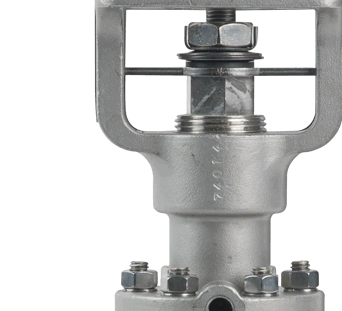
VALVE ACTUATOR
Valve actuators are devices used to operate valves automatically or manually, converting control signals into mechanical motion to open, close, or modulate the flow of fluids.
The choice of the right actuator for a valve depends on several factors, including the valve size, the required speed of operation, the force needed to operate the valve, environmental conditions, and whether the actuator will be used for on/off, throttling, or proportional control. There are several types of valve actuators, each with its own set of characteristics, advantages, and applications.
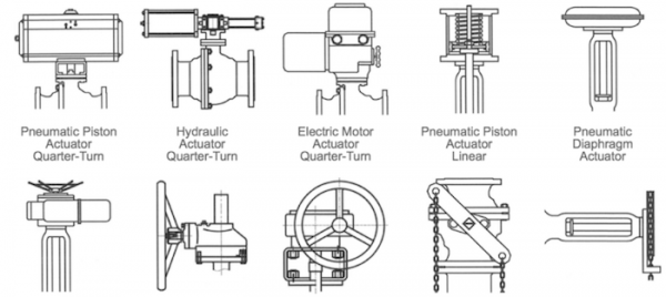
Key types of actuators
Manual Actuators
Manual actuators require human effort to operate the valve, using handwheels, levers, or gears. They are simple and do not rely on an external power source.
- Advantages: Simplicity, no need for power supply, and direct control.
- Applications: Used in applications where automated control is not necessary or as a backup method for operating valves.
A hand-operated or manual valve is generally equipped with a hand wheel that can be rotated clockwise or counter-clockwise to open and/or close the valve (typical for gate and globe valves). Ball, plug, or butterfly are actuated using a lever (manual quarter turn valves).In the following cases, it is not either possible nor advisable to use manual valves:
- Large dimension valves that operate at high pressures
- Valves that need to be controlled from a remote location
- Valves that require, for the nature of the process, a very fast open or close operation
In all these cases, a valve actuator is needed. The actuator produces linear and rotary motion able to open or close a valve (the actual movement depends of course on the type of the valve, linear or quarter turn).
Pneumatic Actuators
Pneumatic actuators use compressed air to generate motion to operate the valve. They are one of the most common types of actuators used in industrial environments due to their simplicity, reliability, and cost-effectiveness.
- Advantages: Rapid response time, inherent explosion safety, and simplicity of design.
- Applications: Widely used in the oil and gas, chemical, water treatment, and manufacturing industries.
Hydraulic Actuators
Hydraulic actuators use pressurized fluid, typically oil, to move the valve. They can produce a high amount of force in a relatively small footprint, making them suitable for large valve operations.
- Advantages: High force output, precise control, and good for heavy-duty applications.
- Applications: Ideal for use in environments where a high force is required, such as in the power generation and offshore industries.
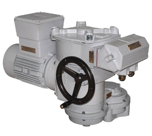
Electric Actuators
Electric actuators use an electric motor to drive the valve to the desired position. They can be easily integrated with electronic control systems for accurate positioning and feedback.
- Advantages: Precise control, easy integration with control systems, and suitable for remote operation.
- Applications: Commonly used in HVAC, water treatment, and light industrial applications.
Electro-Hydraulic Actuators
Electro-hydraulic actuators combine electric and hydraulic technologies. An electric motor drives a hydraulic pump, which then moves the actuator to operate the valve.
- Advantages: Combines the precision of electric actuators with the power of hydraulic actuators, suitable for remote and automatic control.
- Applications: Useful in applications requiring precise control and high force, such as in large valve operations and safety shutdown systems.
Gas over-oil Actuators
A gas-over-oil actuator is a type of valve actuator designed for the automation of valve operations, leveraging a combination of high-pressure gas and hydraulic oil to generate the force necessary for valve movement. This actuation method is particularly favored in the oil and gas industry, especially for remote pipeline applications or in environments where electrical power is scarce or non-existent. Here’s how it works and why it’s beneficial:
How It Works
- Mechanism: In a gas-over-oil actuator, pressurized gas (often natural gas from the pipeline itself) is used to exert force on a hydraulic fluid (oil), which is then directed to move the actuator piston. This piston movement is mechanically linked to a valve, enabling it to open, close, or modulate the flow as required.
- Components: The actuator typically consists of a gas pressure chamber, an oil reservoir, control valves for directing the flow of gas and oil, and a piston or diaphragm that converts the pressure into mechanical motion.
Advantages
- Remote Operation: Since they can utilize the pipeline gas itself as a power source, gas-over-oil actuators are ideal for remote locations where electrical power is unavailable.
- Safety: They are inherently safe for use in explosive atmospheres, as they do not require electricity and minimize the risk of ignition.
- Reliability: This type of actuator is known for its reliability and durability, capable of operating in harsh environments with minimal maintenance.
Applications
- Pipeline Valves: Widely used for the control and safety shutdown valves in natural gas pipelines.
- Offshore Platforms: Suitable for valve actuation in offshore gas extraction platforms, where reliability and safety are paramount.
- Isolated Installations: Ideal for any valve actuation application in remote or difficult-to-access locations within the oil and gas sector.
Gas-over-oil actuators provide a robust and reliable solution for valve automation, combining the advantages of hydraulic systems’ power and precision with the safety and availability of using pipeline gas as a power source. This makes them an essential component in the infrastructure of modern oil and gas extraction and transportation systems.
Solenoid Actuators
Solenoid actuators use electromagnetic solenoids to operate the valve. They are typically used for on/off control in smaller valve applications.
- Advantages: Fast response time, simple design, and suitable for small valves.
- Applications: Commonly used for precise control in fluid power systems, medical equipment, and general on/off applications in various industries.
Each type of valve actuator offers distinct advantages and is chosen based on the specific requirements of the application, such as control needs, operating environment, and valve size. Understanding the different types of actuators and their capabilities is crucial for selecting the right actuator to meet the demands of a particular system or process.
Rotork and Auma actuators have the largest market shares within the petrochemical industry.


9 Responses
There are a lot of options available in the market, so why would one choose ZFA valves over everyone else? Because ZFA valve are top-tier industrial valve manufacturers. Not only that, there are a few more points to that. One is that the engineers who build these valves are precise and efficient. The second is the heck load of customizable options. The third and probably the most important one is that strict quality control and regulation over the staff.
What material?
stainless steel?
WHAT is the HB hardness?
Ivan, in the previous conversation, we discussed valve parts such as the body, bonnet, and trim. While the specific material used for these valve parts was not mentioned in the excerpt, it is common for them to be made of stainless steel due to its durability and corrosion resistance. As for the HB hardness, it refers to the Brinell hardness, which is a measure of a material’s resistance to indentation. The HB hardness value for stainless steel can vary depending on the specific grade and heat treatment it undergoes. Different applications may require different hardness levels to ensure optimal performance.
We usually work in smaller sizes. Even though we usually work with (instrumental) compared to the industrial materials, it is all the same in terms of components. Thank you for writing this!
Dear sir,
we need urgent price for Parts# M3480-2 BONNET ,VALVE,SOLENOID (0.75 IPS/110VAC 2 WAY . QTY-6 .
Please can you urgently quote us with urgent delivery time including freight charges EX-work jeddah to saudi Arabia.
Kindest Regards
ABDUL
Sales & Marketing Manager
International Maritime Trading Est.
Office # 316 3rd Floor
Salma Commercial Center
Madina Road Jeddah – 21464
Kingdom of Saudi Arabia
Tel: +966 12 6532036
Fax:+9661 2 6141265
Mobile:+966 563276478
Email: int.marine.est@gmail.com
Thanks for sharing a blog about valve parts. I especially enjoyed reading the details. Let us know if you want information about valves for an upcoming article.
I didn’t know that as the temperature increases, stainless steel becomes necessary. I might as well get the metal now. That way I don’t have to change them as the temperature rises eventually.
Thanks for pointing out that there are different packings available in different materials for the valves. I hope to find the best one for the valves of my property to ensure that we are safe once we can move into this property this year. I should seek the advice of a professional to really choose the right pieces of equipment needed related to this.
WATER FLOOD STATION
GATE VALVE , RF , 125-250 AARH , CS . BODY AND BONNET , 11-13 % CROMETRIM , HARD FACED SAET RING AND DISC , FLEXIBLE WEDGE , FULL PORTDESIGN BOLTED BONNET , OS &Y ., PER API 600/ASME
B 16.34 & ASMEB 16.10
VALVES SHALL BE TESTED ACCORDING TO API 598 4″ 150 #
CHECK VALVE ( 4″ #150 ) , RTJ , SWING TYPE , CS. BODY & CAP & DISC & SEAT & RING & HING AND HING PIN , AS PER API 6D/BS 5153 , ASTM A216 , TESTED AS PER API 598 / ASME B16.34