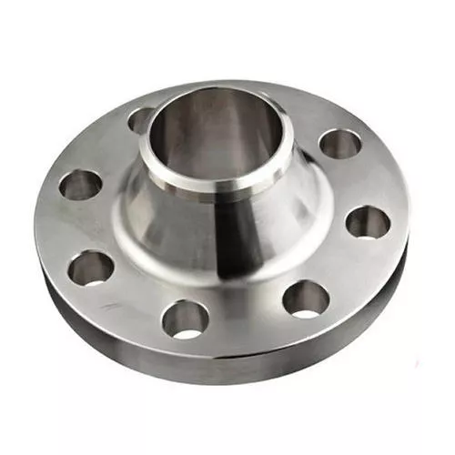

ASME WELDING NECK FLANGE DIMENSIONS & WEIGHTS
The article shows the ASME B16.5 dimensions and weights for weld-neck flanges.
WN FLANGE SIZES IN INCHES

WN CLASS 150
Weld neck flange dimensions class 150 (ASME B16.5) in inches
| Flange NPS | Inside Diameter | Outside Diameter | Bolt Circle (BC) | Raised Face (R) | Raised Face (RF) | H | H1 | Raised Face Thickness (T) | T1 | Flat Face Thickness (T2) | Bolt Hole (B) | No. of Bolt Holes |
|---|---|---|---|---|---|---|---|---|---|---|---|---|
| 1/2″ | 0.62″ | 3.50″ | 2.38″ | 1.38″ | .063″ | 1.19″ | 0.84″ | 1.88″ | .38″ | 1.82″ | .62″ | 4 |
| 3/4″ | 0.82″ | 3.88″ | 2.75″ | 1.69″ | .063″ | 1.50″ | 1.05″ | 2.06″ | .44″ | 2.00″ | .62″ | 4 |
| 1″ | 1.05″ | 4.25″ | 3.12″ | 2.00″ | .063″ | 1.94″ | 1.32″ | 2.19″ | .50″ | 2.13″ | .62″ | 4 |
| 1-1/4″ | 1.38″ | 4.62″ | 3.50″ | 2.50″ | .063″ | 2.31″ | 1.66″ | 2.25″ | .56″ | 2.19″ | .62″ | 4 |
| 1-1/2″ | 1.61″ | 5.00″ | 3.88″ | 2.88″ | .063″ | 2.56″ | 1.90″ | 2.44″ | .62″ | 2.38″ | .62″ | 4 |
| 2″ | 2.07″ | 6.00″ | 4.75″ | 3.62″ | .063″ | 3.06″ | 2.38″ | 2.50″ | .69″ | 2.44″ | .75″ | 4 |
| 2-1/2″ | 2.47″ | 7.00″ | 5.50″ | 4.12″ | .063″ | 3.56″ | 2.88″ | 2.75″ | .82″ | 2.69″ | .75″ | 4 |
| 3″ | 3.07″ | 7.50″ | 6.00″ | 5.00″ | .063″ | 4.25″ | 3.50″ | 2.75″ | .88″ | 2.69″ | .75″ | 4 |
| 3-1/2″ | 3.55″ | 8.50″ | 7.00″ | 5.50″ | .063″ | 4.81″ | 4.00″ | 2.81″ | .88″ | 2.75″ | .75″ | 8 |
| 4″ | 4.03″ | 9.00″ | 7.50″ | 6.19″ | .063″ | 5.31″ | 4.50″ | 3.00″ | .88″ | 2.94″ | .75″ | 8 |
| 5″ | 5.05″ | 10.00″ | 8.50″ | 7.31″ | .063″ | 6.44″ | 5.56″ | 3.50″ | .88″ | 3.44″ | .88″ | 8 |
| 6″ | 6.07″ | 11.00″ | 9.50″ | 8.50″ | .063″ | 7.56″ | 6.63″ | 3.50″ | .94″ | 3.44″ | .88″ | 8 |
| 8″ | 7.98″ | 13.50″ | 11.75″ | 10.62″ | .063″ | 9.69″ | 8.63″ | 4.00″ | 1.06″ | 3.94″ | .88″ | 8 |
| 10″ | 10.02″ | 16.00″ | 14.25″ | 12.75″ | .063″ | 12.00″ | 10.75″ | 4.00″ | 1.13″ | 3.94″ | 1.00″ | 12 |
| 12″ | 12.00″ | 19.00″ | 17.00″ | 15.00″ | .063″ | 14.38″ | 12.75″ | 4.50″ | 1.19″ | 4.44″ | 1.00″ | 12 |
| 14″ | 13.25″ | 21.00″ | 18.75″ | 16.25″ | .063″ | 15.75″ | 14.00″ | 5.00″ | 1.32″ | 4.94″ | 1.12″ | 12 |
| 16″ | 15.25″ | 23.50″ | 21.25″ | 18.50″ | .063″ | 18.00″ | 16.00″ | 5.00″ | 1.38″ | 4.94″ | 1.12″ | 16 |
| 18″ | 17.25″ | 25.00″ | 22.75″ | 21.00″ | .063″ | 19.88″ | 18.00″ | 5.50″ | 1.50″ | 5.44″ | 1.25″ | 16 |
| 20″ | 19.25″ | 27.50″ | 25.00″ | 23.00″ | .063″ | 22.00″ | 20.00″ | 5.69″ | 1.63″ | 5.63″ | 1.25″ | 20 |
| 22″ | 21.25″ | 29.50″ | 27.25″ | 25.25″ | .063″ | 24.25″ | 22.00″ | 5.88″ | 1.75″ | 5.82″ | 1.38″ | 20 |
| 24″ | 23.25″ | 32.00″ | 29.50″ | 27.25″ | .063″ | 26.12″ | 24.00″ | 6.00″ | 1.82″ | 5.94″ | 1.38″ | 20 |
WN CLASS 300
Weld neck flange dimensions class 300 (ASME B16.5) in inches
| Flange NPS | Inside Diameter | Outside Diameter | Bolt Circle (BC) | Raised Face (R) | Raised Face (RF) | H | H1 | Raised Face Thickness (T) | T1 | Flat Face Thickness (T2) | Bolt Hole (B) | No. of Bolt Holes |
|---|---|---|---|---|---|---|---|---|---|---|---|---|
| 1/2″ | 0.62″ | 3.75″ | 2.62″ | 1.38″ | .063″ | 1.50″ | 0.84″ | 2.06″ | .50″ | 2.00″ | 0.62″ | 4 |
| 3/4″ | 0.82″ | 4.62″ | 3.25″ | 1.69″ | .063″ | 1.88″ | 1.05″ | 2.25″ | .56″ | 2.19″ | 0.75″ | 4 |
| 1″ | 1.05″ | 4.88″ | 3.50″ | 2.00″ | .063″ | 2.12″ | 1.32″ | 2.44″ | .63″ | 2.38″ | 0.75″ | 4 |
| 1-1/4″ | 1.38″ | 5.25″ | 3.88″ | 2.50″ | .063″ | 2.50″ | 1.66″ | 2.56″ | .69″ | 2.50″ | 0.75″ | 4 |
| 1-1/2″ | 1.61″ | 6.12″ | 4.50″ | 2.88″ | .063″ | 2.75″ | 1.90″ | 2.69″ | .75″ | 2.63″ | 0.88″ | 4 |
| 2″ | 2.07″ | 6.50″ | 5.00″ | 3.62″ | .063″ | 3.31″ | 2.38″ | 2.75″ | .82″ | 2.69″ | 0.75″ | 8 |
| 2-1/2″ | 2.47″ | 7.50″ | 5.88″ | 4.12″ | .063″ | 3.94″ | 2.88″ | 3.00″ | .94″ | 2.94″ | 0.88″ | 8 |
| 3″ | 3.07″ | 8.25″ | 6.62″ | 5.00″ | .063″ | 4.62″ | 3.50″ | 3.12″ | 1.06″ | 3.06″ | 0.88″ | 8 |
| 3-1/2″ | 3.55″ | 9.00″ | 7.25″ | 5.50″ | .063″ | 5.25″ | 4.00″ | 3.19″ | 1.13″ | 3.13″ | 0.88″ | 8 |
| 4″ | 4.03″ | 10.00″ | 7.88″ | 6.19″ | .063″ | 5.75″ | 4.50″ | 3.38″ | 1.19″ | 3.32″ | 0.88″ | 8 |
| 5″ | 5.05″ | 11.00″ | 9.25″ | 7.31″ | .063″ | 7.00″ | 5.56″ | 3.88″ | 1.32″ | 3.82″ | 0.88″ | 8 |
| 6″ | 6.07″ | 12.50″ | 10.62″ | 8.50″ | .063″ | 8.12″ | 6.63″ | 3.88″ | 1.38″ | 3.82″ | 0.88″ | 12 |
| 8″ | 7.98″ | 15.00″ | 13.00″ | 10.62″ | .063″ | 10.25″ | 8.63″ | 4.38″ | 1.56″ | 4.32″ | 1.00″ | 12 |
| 10″ | 10.02″ | 17.50″ | 15.25″ | 12.75″ | .063″ | 12.62″ | 10.75″ | 4.62″ | 1.82″ | 4.56″ | 1.12″ | 16 |
| 12″ | 12.00″ | 20.50″ | 17.75″ | 15.00″ | .063″ | 14.75″ | 12.75″ | 5.12″ | 1.94″ | 5.06″ | 1.25″ | 16 |
| 14″ | 13.25″ | 23.00″ | 20.25″ | 16.25″ | .063″ | 16.75″ | 14.00″ | 5.62″ | 2.06″ | 5.56″ | 1.25″ | 20 |
| 16″ | 15.25″ | 25.50″ | 22.50″ | 18.50″ | .063″ | 19.00″ | 16.00″ | 5.75″ | 2.19″ | 5.69″ | 1.38″ | 20 |
| 18″ | 17.25″ | 28.00″ | 24.75″ | 21.00″ | .063″ | 21.00″ | 18.00″ | 6.25″ | 2.32″ | 6.19″ | 1.38″ | 24 |
| 20″ | 19.25″ | 30.50″ | 27.00″ | 23.00″ | .063″ | 23.12″ | 20.00″ | 6.38″ | 2.44″ | 6.32″ | 1.38″ | 24 |
| 22″ | 21.25″ | 33.00″ | 29.25″ | 25.25″ | .063″ | 25.25″ | 22.00″ | 6.50″ | 2.57″ | 6.44″ | 1.62″ | 24 |
| 24″ | 23.25″ | 36.00″ | 32.0″ | 27.25″ | .063″ | 27.62″ | 24.00″ | 6.62″ | 2.69″ | 6.56″ | 1.62″ | 24 |
WN CLASS 400
Weld neck flange dimensions class 400 (ASME B16.5) in inches
| Flange NPS | Inside Diameter | Outside Diameter | Bolt Circle (BC) | Raised Face (R) | Raised Face (RF) | H | H1 | Raised Face Thickness (T) | T1 | Flat Face Thickness (T2) | Bolt Hole (B) | No. of Bolt Holes |
|---|---|---|---|---|---|---|---|---|---|---|---|---|
| 1/2″ | .55″ | 3.75″ | 2.62″ | 1.38″ | .250″ | 1.50″ | 0.84″ | 2.31″ | 0.56″ | 2.06″ | 0.62″ | 4 |
| 3/4″ | .74″ | 4.62″ | 3.25″ | 1.69″ | .250″ | 1.88″ | 1.05″ | 2.50″ | 0.62″ | 2.25″ | 0.75″ | 4 |
| 1″ | .96″ | 4.88″ | 3.50″ | 2.00″ | .250″ | 2.12″ | 1.32″ | 2.69″ | 0.69″ | 2.44″ | 0.75″ | 4 |
| 1-1/4″ | 1.28″ | 5.25″ | 3.88″ | 2.50″ | .250″ | 2.50″ | 1.66″ | 2.87″ | 0.81″ | 2.62″ | 0.75″ | 4 |
| 1-1/2″ | 1.50″ | 6.12″ | 4.50″ | 2.88″ | .250″ | 2.75″ | 1.90″ | 3.00″ | 0.88″ | 2.75″ | 0.88″ | 4 |
| 2″ | 1.94″ | 6.50″ | 5.00″ | 3.62″ | .250″ | 3.31″ | 2.38″ | 3.13″ | 1.00″ | 2.88″ | 0.75″ | 8 |
| 2-1/2″ | 2.32″ | 7.50″ | 5.88″ | 4.12″ | .250″ | 3.94″ | 2.88″ | 3.37″ | 1.12″ | 3.12″ | 0.88″ | 8 |
| 3″ | 2.90″ | 8.25″ | 6.62″ | 5.00″ | .250″ | 4.62″ | 3.50″ | 3.50″ | 1.25″ | 3.25″ | 0.88″ | 8 |
| 3-1/2″ | 3.36″ | 9.00″ | 7.25″ | 5.50″ | .250″ | 5.25″ | 4.00″ | 3.63″ | 1.38″ | 3.38″ | 1.00″ | 8 |
| 4″ | 3.83″ | 10.00″ | 7.88″ | 6.19″ | .250″ | 5.75″ | 4.50″ | 3.75″ | 1.38″ | 3.50″ | 1.00″ | 8 |
| 5″ | 4.81″ | 11.00″ | 9.25″ | 7.31″ | .250″ | 7.00″ | 5.56″ | 4.25″ | 1.50″ | 4.00″ | 1.00″ | 8 |
| 6″ | 5.76″ | 12.50″ | 10.62″ | 8.50″ | .250″ | 8.12″ | 6.63″ | 4.31″ | 1.62″ | 4.06″ | 1.00″ | 12 |
| 8″ | 7.63″ | 15.00″ | 13.00″ | 10.62″ | .250″ | 10.25″ | 8.63″ | 4.87″ | 1.88″ | 4.62″ | 1.12″ | 12 |
| 10″ | 9.75″ | 17.50″ | 15.25″ | 12.75″ | .250″ | 12.62″ | 10.75″ | 5.13″ | 2.12″ | 4.88″ | 1.25″ | 16 |
| 12″ | 11.75″ | 20.50″ | 17.75″ | 15.00″ | .250″ | 14.75″ | 12.75″ | 5.63″ | 2.25″ | 5.38″ | 1.38″ | 16 |
| 14″ | 13.00″ | 23.00″ | 20.25″ | 16.25″ | .250″ | 16.75″ | 14.00″ | 6.13″ | 2.38″ | 5.88″ | 1.38″ | 20 |
| 16″ | 15.00″ | 25.50″ | 22.50″ | 18.50″ | .250″ | 19.00″ | 16.00″ | 6.25″ | 2.50″ | 6.00″ | 1.50″ | 20 |
| 18″ | 17.00″ | 28.00″ | 24.75″ | 21.00″ | .250″ | 21.00″ | 18.00″ | 6.75″ | 2.62″ | 6.50″ | 1.50″ | 24 |
| 20″ | 19.00″ | 30.50″ | 27.00″ | 23.00″ | .250″ | 23.12″ | 20.00″ | 6.87″ | 2.75″ | 6.62″ | 1.62″ | 24 |
| 22″ | 21.00″ | 33.00″ | 29.25″ | 25.25″ | .250″ | 25.25″ | 22.00″ | 7.00″ | 2.88″ | 6.75″ | 1.75″ | 24 |
| 24″ | 23.00″ | 36.00″ | 32.00″ | 27.25″ | .250″ | 27.62″ | 24.00″ | 7.13″ | 3.00″ | 6.88″ | 1.88″ | 24 |
WN CLASS 600
Weld neck flange dimensions class 600 (ASME B16.5) in inches
| Flange NPS | Inside Diameter | Outside Diameter | Bolt Circle (BC) | Raised Face (R) | Raised Face (RF) | H | H1 | Raised Face Thickness (T) | T1 | Flat Face Thickness (T2) | Bolt Hole (B) | No. of Bolt Holes |
|---|---|---|---|---|---|---|---|---|---|---|---|---|
| 1/2″ | 0.55″ | 3.75″ | 2.62″ | 1.38″ | .250″ | 1.50″ | 0.84″ | 2.31″ | 0.56″ | 2.06″ | 0.62″ | 4 |
| 3/4″ | 0.74″ | 4.62″ | 3.25″ | 1.69″ | .250″ | 1.88″ | 1.05″ | 2.50″ | 0.62″ | 2.25″ | 0.75″ | 4 |
| 1″ | 0.96″ | 4.88″ | 3.50″ | 2.00″ | .250″ | 2.12″ | 1.32″ | 2.69″ | 0.69″ | 2.44″ | 0.75″ | 4 |
| 1-1/4″ | 1.28″ | 5.25″ | 3.88″ | 2.50″ | .250″ | 2.50″ | 1.66″ | 2.87″ | 0.81″ | 2.62″ | 0.75″ | 4 |
| 1-1/2″ | 1.50″ | 6.12″ | 4.50″ | 2.88″ | .250″ | 2.75″ | 1.90″ | 3.00″ | 0.88″ | 2.75″ | 0.88″ | 4 |
| 2″ | 1.94″ | 6.50″ | 5.00″ | 3.62″ | .250″ | 3.31″ | 2.38″ | 3.13″ | 1.00″ | 2.88″ | 0.75″ | 8 |
| 2-1/2″ | 2.32″ | 7.50″ | 5.88″ | 4.12″ | .250″ | 3.94″ | 2.88″ | 3.37″ | 1.12″ | 3.12″ | 0.88″ | 8 |
| 3″ | 2.90″ | 8.25″ | 6.62″ | 5.00″ | .250″ | 4.62″ | 3.50″ | 3.50″ | 1.25″ | 3.25″ | 0.88″ | 8 |
| 3-1/2″ | 3.36″ | 9.00″ | 7.25″ | 5.50″ | .250″ | 5.25″ | 4.00″ | 3.63″ | 1.38″ | 3.38″ | 1.00″ | 8 |
| 4″ | 3.83″ | 10.75″ | 8.50″ | 6.19″ | .250″ | 6.00″ | 4.50″ | 4.25″ | 1.5″ | 4.00″ | 1.00″ | 8 |
| 5″ | 4.81″ | 13.00″ | 10.50″ | 7.31″ | .250″ | 7.44″ | 5.56″ | 4.75″ | 1.75″ | 4.50″ | 1.12″ | 8 |
| 6″ | 5.76″ | 14.00″ | 11.50″ | 8.50″ | .250″ | 8.75″ | 6.63″ | 4.87″ | 1.88″ | 4.62″ | 1.12″ | 12 |
| 8″ | 7.63″ | 16.50″ | 13.75″ | 10.62″ | .250″ | 10.75″ | 8.63″ | 5.50″ | 2.19″ | 5.25″ | 1.25″ | 12 |
| 10″ | 9.75″ | 20.00″ | 17.00″ | 12.75″ | .250″ | 13.5″ | 10.75″ | 6.25″ | 2.50″ | 6.00″ | 1.38″ | 16 |
| 12″ | 11.75″ | 22.00″ | 19.25″ | 15.00″ | .250″ | 15.75″ | 12.75″ | 6.37″ | 2.62″ | 6.12″ | 1.38″ | 20 |
| 14″ | 13.00″ | 23.75″ | 20.75″ | 16.25″ | .250″ | 17.00″ | 14.00″ | 6.75″ | 2.75″ | 6.50″ | 1.50″ | 20 |
| 16″ | 15.00″ | 27.00″ | 23.75″ | 18.50″ | .250″ | 19.50″ | 16.00″ | 7.25″ | 3.00″ | 7.00″ | 1.62″ | 20 |
| 18″ | 17.00″ | 29.25″ | 25.75″ | 21.00″ | .250″ | 21.50″ | 18.00″ | 7.50″ | 3.25″ | 7.25″ | 1.75″ | 20 |
| 20″ | 19.00″ | 32.00″ | 28.50″ | 23.00″ | .250″ | 24.00″ | 20.00″ | 7.75″ | 3.50″ | 7.50″ | 1.75″ | 24 |
| 22″ | 21.00″ | 34.25″ | 30.63″ | 25.25″ | .250″ | 26.25″ | 22.00″ | 8.00″ | 3.75″ | 7.75″ | 1.75″ | 24 |
| 24″ | 23.00″ | 37.00″ | 33.00″ | 27.25″ | .250″ | 28.25″ | 24.00″ | 8.25″ | 4.00″ | 8.00″ | 2.00″ | 24 |
WN CLASS 900
Weld neck flange dimensions class 900 (ASME B16.5) in inches
| Flange NPS | Inside Diameter | Outside Diameter | Bolt Circle (BC) | Raised Face (R) | Raised Face (RF) | H | H1 | Raised Face Thickness (T) | T1 | Flat Face Thickness (T2) | Bolt Hole (B) | No. of Bolt Holes |
|---|---|---|---|---|---|---|---|---|---|---|---|---|
| 3″ | 2.90″ | 9.50″ | 7.50″ | 5.00″ | .250″ | 5.00″ | 3.50″ | 4.25″ | 1.50″ | 4.00″ | 1.00″ | 8 |
| 4″ | 3.83″ | 11.50″ | 9.25″ | 6.19″ | .250″ | 6.25″ | 4.50″ | 4.75″ | 1.75″ | 4.50″ | 1.25″ | 8 |
| 5″ | 4.81″ | 13.75″ | 11.00″ | 7.31″ | .250″ | 7.50″ | 5.56″ | 5.25″ | 3.00″ | 5.00″ | 1.38″ | 8 |
| 6″ | 5.76″ | 15.00″ | 12.50″ | 8.50″ | .250″ | 9.25″ | 6.63″ | 5.75″ | 2.19″ | 5.50″ | 1.25″ | 12 |
| 8″ | 7.63″ | 18.50″ | 15.50″ | 10.63″ | .250″ | 11.75″ | 8.63″ | 6.63″ | 2.50″ | 6.38″ | 1.50″ | 12 |
| 10″ | 9.75″ | 21.50″ | 18.50″ | 12.75″ | .250″ | 14.50″ | 10.75″ | 7.50″ | 2.75″ | 7.25″ | 1.50″ | 16 |
| 12″ | 11.75″ | 24.00″ | 21.00″ | 15.00″ | .250″ | 16.50″ | 12.75″ | 8.13″ | 3.13″ | 7.88″ | 1.50″ | 20 |
| 14″ | 13.00″ | 25.25″ | 22.00″ | 16.25″ | .250″ | 17.75″ | 14.00″ | 8.63″ | 3.38″ | 8.38″ | 1.63″ | 20 |
| 16″ | 15.00″ | 27.75″ | 24.25″ | 18.50″ | .250″ | 20.00″ | 16.00″ | 8.75″ | 3.50″ | 8.50″ | 1.75″ | 20 |
| 18″ | 17.00″ | 31.00″ | 27.00″ | 21.00″ | .250″ | 22.25″ | 18.00″ | 9.25″ | 4.00″ | 9.00″ | 2.00″ | 20 |
| 20″ | 19.00″ | 33.75″ | 29.50″ | 23.00″ | .250″ | 24.50″ | 20.00″ | 10.00″ | 4.25″ | 9.75″ | 2.13″ | 20 |
| 24″ | 23.00″ | 41.00″ | 35.50″ | 27.25″ | .250″ | 29.50″ | 24.00″ | 11.75″ | 5.50″ | 11.50″ | 2.63″ | 20 |
WN CLASS 1500
Weld neck flange dimensions class 1500 (ASME B16.5) in inches
| Flange NPS | Inside Diameter | Outside Diameter | Bolt Circle (BC) | Raised Face (R) | Raised Face (RF) | H | H1 | Raised Face Thickness (T) | T1 | Flat Face Thickness (T2) | Bolt Hole (B) | No. of Bolt Holes |
|---|---|---|---|---|---|---|---|---|---|---|---|---|
| 1/2″ | 0.55″ | 4.75″ | 3.25″ | 1.38″ | .250″ | 1.50″ | 0.84″ | 2.63″ | 0.88″ | 2.38″ | 0.88″ | 4 |
| 3/4″ | 0.74″ | 5.13″ | 3.50″ | 1.69″ | .250″ | 1.75″ | 1.05″ | 3.00″ | 1.00″ | 2.75″ | 0.88″ | 4 |
| 1″ | 0.96″ | 5.88″ | 4.00″ | 2.00″ | .250″ | 2.06″ | 1.32″ | 3.13″ | 1.13″ | 2.88″ | 1.00″ | 4 |
| 1-1/4″ | 1.28″ | 6.25″ | 4.38″ | 2.50″ | .250″ | 2.50″ | 1.66″ | 3.13″ | 1.13″ | 2.88″ | 1.00″ | 4 |
| 1-1/2″ | 1.50″ | 7.00″ | 4.88″ | 2.88″ | .250″ | 2.75″ | 1.90″ | 3.50″ | 1.25″ | 3.25″ | 1.13″ | 4 |
| 2″ | 1.94″ | 8.50″ | 6.50″ | 3.63″ | .250″ | 4.13″ | 2.38″ | 4.25″ | 1.50″ | 4.00″ | 1.00″ | 8 |
| 2-1/2″ | 2.32″ | 9.63″ | 7.50″ | 4.13″ | .250″ | 4.88″ | 2.88″ | 4.38″ | 1.63″ | 4.13″ | 1.13″ | 8 |
| 3″ | 2.90″ | 10.50″ | 8.00″ | 5.00″ | .250″ | 5.25″ | 3.50″ | 4.88″ | 1.88″ | 4.63″ | 1.25″ | 8 |
| 4″ | 3.83″ | 12.25″ | 9.50″ | 6.19″ | .250″ | 6.38″ | 4.50″ | 5.13″ | 2.13″ | 4.88″ | 1.38″ | 8 |
| 5″ | 4.81″ | 14.75″ | 11.50″ | 7.31″ | .250″ | 7.75″ | 5.56″ | 6.38″ | 2.88″ | 6.13″ | 1.63″ | 8 |
| 6″ | 5.76″ | 15.50″ | 12.50″ | 8.50″ | .250″ | 9.00″ | 6.63″ | 7.00″ | 3.25″ | 6.75″ | 1.50″ | 12 |
| 8″ | 7.63″ | 19.00″ | 15.50″ | 10.63″ | .250″ | 11.50″ | 8.63″ | 8.63″ | 3.63″ | 8.38″ | 1.75″ | 12 |
| 10″ | 9.75″ | 23.00″ | 19.00″ | 12.75″ | .250″ | 14.50″ | 10.75″ | 10.25″ | 4.25″ | 10.00″ | 2.00″ | 12 |
| 12″ | 11.75″ | 26.50″ | 22.50″ | 15.00″ | .250″ | 17.75″ | 12.75″ | 11.38″ | 4.88″ | 11.13″ | 2.13″ | 16 |
| 14″ | 13.00″ | 29.50″ | 25.00″ | 16.25″ | .250″ | 19.50″ | 14.00″ | 12.00″ | 5.25″ | 11.75″ | 2.38″ | 16 |
| 16″ | 15.00″ | 32.50″ | 27.75″ | 18.50″ | .250″ | 21.75″ | 16.00″ | 12.50″ | 5.75″ | 12.25″ | 2.63″ | 16 |
| 18″ | 17.00″ | 36.00″ | 30.50″ | 21.00″ | .250″ | 23.50″ | 18.00″ | 13.13″ | 6.38″ | 12.88″ | 2.88″ | 16 |
| 20″ | 19.00″ | 38.75″ | 32.75″ | 23.00″ | .250″ | 25.25″ | 20.00″ | 14.25″ | 7.00″ | 14.00″ | 3.13″ | 16 |
| 24″ | 23.00″ | 46.00″ | 39.00″ | 27.25″ | .250″ | 30.00″ | 24.00″ | 16.25″ | 8.00″ | 16.00″ | 3.63″ | 16 |
WN CLASS 2500
Weld neck flange dimensions class 2500 (ASME B16.5) in inches
| Flange NPS | Inside Diameter | Outside Diameter | Bolt Circle (BC) | Raised Face (R) | Raised Face (RF) | H | H1 | Raised Face Thickness (T) | T1 | Flat Face Thickness (T2) | Bolt Hole (B) | No. of Bolt Holes |
|---|---|---|---|---|---|---|---|---|---|---|---|---|
| 1/2″ | 0.55″ | 5.25″ | 3.50″ | 1.38″ | .250″ | 1.69″ | 0.84″ | 3.13″ | 1.19″ | 2.88″ | 0.88″ | 4 |
| 3/4″ | 0.74″ | 5.50″ | 3.75″ | 1.69″ | .250″ | 2.00″ | 1.05″ | 3.38″ | 1.25″ | 3.13″ | 0.88″ | 4 |
| 1″ | 0.96″ | 6.25″ | 4.25″ | 2.00″ | .250″ | 2.25″ | 1.32″ | 3.75″ | 1.38″ | 3.50″ | 1.00″ | 4 |
| 1-1/4″ | 1.28″ | 7.25″ | 5.13″ | 2.50″ | .250″ | 2.88″ | 1.66″ | 4.00″ | 1.50″ | 3.75″ | 1.13″ | 4 |
| 1-1/2″ | 1.50″ | 8.00″ | 5.75″ | 2.88″ | .250″ | 3.13″ | 1.90″ | 4.63″ | 1.75″ | 4.38″ | 1.25″ | 4 |
| 2″ | 1.94″ | 9.25″ | 6.75″ | 3.63″ | .250″ | 3.75″ | 2.38″ | 5.25″ | 2.00″ | 5.00″ | 1.13″ | 8 |
| 2-1/2″ | 2.32″ | 10.50″ | 7.75″ | 4.13″ | .250″ | 4.50″ | 2.88″ | 5.88″ | 2.25″ | 5.63″ | 1.25″ | 8 |
| 3″ | 2.90″ | 12.00″ | 9.00″ | 5.00″ | .250″ | 5.25″ | 3.50″ | 6.88″ | 2.63″ | 6.63″ | 1.38″ | 8 |
| 4″ | 3.83″ | 14.00″ | 10.75″ | 6.19″ | .250″ | 6.50″ | 4.50″ | 7.75″ | 3.00″ | 7.50″ | 1.63″ | 8 |
| 5″ | 4.81″ | 16.50″ | 12.75″ | 7.31″ | .250″ | 8.00″ | 5.56″ | 9.25″ | 3.63″ | 9.00″ | 1.88″ | 8 |
| 6″ | 5.76″ | 19.00″ | 14.50″ | 8.50″ | .250″ | 9.25″ | 6.63″ | 11.00″ | 4.25″ | 10.75″ | 2.13″ | 8 |
| 8″ | 7.63″ | 21.75″ | 17.25″ | 10.63″ | .250″ | 12.00″ | 8.63″ | 12.75″ | 5.00″ | 12.50″ | 2.13″ | 12 |
| 10″ | 9.75″ | 26.50″ | 21.25″ | 12.75″ | .250″ | 14.75″ | 10.75″ | 16.75″ | 6.50″ | 16.50″ | 2.63″ | 12 |
| 12″ | 11.75″ | 30.00″ | 24.38″ | 15.00″ | .250″ | 17.38″ | 12.75″ | 18.50″ | 7.25″ | 18.25″ | 2.88″ | 12 |
WN FLANGE SIZES IN MILLIMETERS
WN CLASS 150
Weld neck flange dimensions class 150 (ASME B16.5) in millimeters
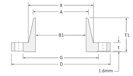
| Size inch | D mm | X mm | G mm | t mm | B1 mm | T1 mm | A mm |
|---|---|---|---|---|---|---|---|
| 1/2 | 89 | 30.2 | 35.1 | 11.2 | 15.7 | 47.8 | 21.3 |
| 3/4 | 99 | 38.1 | 42.9 | 12.7 | 20.8 | 52.3 | 26.7 |
| 1 | 108 | 49.3 | 50.8 | 14.2 | 26.7 | 55.6 | 33.5 |
| 1¼ | 117 | 58.7 | 63.5 | 15.7 | 35.1 | 57.2 | 42.2 |
| 1½ | 127 | 65.0 | 73.2 | 17.5 | 40.9 | 62.0 | 48.3 |
| 2 | 152 | 77.7 | 91.9 | 19.1 | 52.6 | 63.5 | 60.5 |
| 2½ | 178 | 90.4 | 104.6 | 22.4 | 62.7 | 69.9 | 73.2 |
| 3 | 191 | 108.0 | 127.0 | 23.9 | 78.0 | 69.9 | 88.9 |
| 3½ | 216 | 122.2 | 139.7 | 23.9 | 90.2 | 71.4 | 101.6 |
| 4 | 229 | 134.9 | 157.2 | 23.9 | 102.4 | 76.2 | 114.3 |
| 5 | 254 | 163.6 | 185.7 | 23.9 | 128.3 | 88.9 | 141.2 |
| 6 | 279 | 192.0 | 215.9 | 25.4 | 154.2 | 88.9 | 168.4 |
| 8 | 343 | 246.1 | 269.7 | 28.4 | 202.7 | 101.6 | 218.2 |
| 10 | 406 | 304.8 | 323.9 | 30.2 | 254.5 | 101.6 | 273.1 |
| 12 | 483 | 365.3 | 381.0 | 31.8 | 304.8 | 114.3 | 323.9 |
| 14 | 533 | 400.1 | 412.8 | 35.1 | 336.6 | 127.0 | 355.6 |
| 16 | 597 | 457.2 | 469.9 | 36.6 | 387.4 | 127.0 | 406.4 |
| 18 | 635 | 505.0 | 533.4 | 39.6 | 438.2 | 139.7 | 457.2 |
| 20 | 699 | 558.8 | 584.2 | 42.9 | 489.0 | 144.5 | 508.0 |
| 24 | 813 | 663.4 | 692.2 | 47.8 | 590.6 | 152.4 | 609.6 |
| Size | Bolt Drilling | Bolting Requirements | |||||
|---|---|---|---|---|---|---|---|
| inch | Bolt circle Diameter mm | Holes # | Holes Dia. mm | Bolt Dia. inch. | Length FF Flange | Length RF Flange | Length RTJ Flange |
| 1/2 | 60.5 | 4 | 15.7 | 1/2 | 50.8 | 57.2 | – |
| 3/4 | 69.9 | 4 | 15.7 | 1/2 | 50.8 | 63.5 | – |
| 1 | 79.2 | 4 | 15.7 | 1/2 | 57.2 | 63.5 | 76.2 |
| 1¼ | 88.9 | 4 | 15.7 | 1/2 | 57.2 | 69.9 | 82.6 |
| 1½ | 98.6 | 4 | 15.7 | 1/2 | 63.5 | 69.9 | 82.6 |
| 2 | 120.7 | 4 | 19.1 | 5/8 | 69.9 | 82.6 | 95.3 |
| 2½ | 139.7 | 4 | 19.1 | 5/8 | 76.2 | 88.9 | 101.6 |
| 3 | 152.4 | 4 | 19.1 | 5/8 | 76.2 | 88.9 | 101.6 |
| 3½ | 177.8 | 8 | 19.1 | 5/8 | 76.2 | 88.9 | 101.6 |
| 4 | 190.5 | 8 | 19.1 | 5/8 | 76.2 | 88.9 | 101.6 |
| 5 | 215.9 | 8 | 22.4 | 3/4 | 82.6 | 95.3 | 108.0 |
| 6 | 241.3 | 8 | 22.4 | 3/4 | 82.6 | 101.6 | 114.3 |
| 8 | 298.5 | 8 | 22.4 | 3/4 | 88.9 | 108.0 | 120.7 |
| 10 | 362.0 | 12 | 25.4 | 7/8 | 101.6 | 114.3 | 127.0 |
| 12 | 431.8 | 12 | 25.4 | 7/8 | 101.6 | 120.7 | 133.4 |
| 14 | 476.3 | 12 | 28.4 | 1 | 114.3 | 133.4 | 146.1 |
| 16 | 539.8 | 16 | 28.4 | 1 | 114.3 | 133.4 | 146.1 |
| 18 | 577.9 | 16 | 31.8 | 11/8 | 127.0 | 146.1 | 158.8 |
| 20 | 635.0 | 20 | 31.8 | 11/8 | 139.7 | 158.8 | 171.5 |
| 24 | 749.3 | 20 | 35.1 | 1¼ | 152.4 | 171.5 | 184.2 |
WN CLASS 300
Weld neck flange dimensions class 300 (ASME B16.5) in millimeters
| Size inch | D mm | X mm | G mm | t mm | B1 mm | T1 mm | A mm |
|---|---|---|---|---|---|---|---|
| 1/2 | 95 | 38.1 | 35.1 | 14.2 | 15.7 | 52.3 | 21.3 |
| 3/4 | 117 | 47.8 | 42.9 | 15.7 | 20.8 | 57.2 | 26.7 |
| 1 | 124 | 53.8 | 50.8 | 17.5 | 26.7 | 62.0 | 33.5 |
| 1¼ | 133 | 63.5 | 63.5 | 19.1 | 35.1 | 65.0 | 42.2 |
| 1½ | 155 | 69.9 | 73.2 | 20.6 | 40.9 | 68.3 | 48.3 |
| 2 | 165 | 84.1 | 91.9 | 22.4 | 52.6 | 69.9 | 60.5 |
| 2½ | 191 | 100.1 | 104.6 | 25.4 | 62.7 | 76.2 | 73.2 |
| 3 | 210 | 117.3 | 127.0 | 28.4 | 78.0 | 79.2 | 88.9 |
| 3½ | 229 | 133.4 | 139.7 | 30.2 | 90.2 | 81.0 | 101.6 |
| 4 | 254 | 146.1 | 157.2 | 31.8 | 102.4 | 85.9 | 114.3 |
| 5 | 279 | 177.8 | 185.7 | 35.1 | 128.3 | 98.6 | 141.2 |
| 6 | 318 | 206.2 | 215.9 | 36.6 | 154.2 | 98.6 | 168.4 |
| 8 | 381 | 260.4 | 269.7 | 41.1 | 202.7 | 111.3 | 219.2 |
| 10 | 445 | 320.5 | 323.9 | 47.8 | 254.5 | 117.3 | 273.1 |
| 12 | 521 | 374.7 | 381.0 | 50.8 | 304.8 | 130.0 | 323.9 |
| 14 | 584 | 425.5 | 412.8 | 63.8 | 336.6 | 142.7 | 355.6 |
| 16 | 648 | 482.6 | 469.9 | 57.2 | 387.4 | 146.1 | 406.4 |
| 18 | 711 | 533.4 | 533.4 | 60.5 | 438.2 | 158.8 | 457.2 |
| 20 | 775 | 587.2 | 584.2 | 63.5 | 489.0 | 162.1 | 508.0 |
| 24 | 914 | 701.5 | 692.2 | 69.9 | 590.6 | 168.1 | 609.6 |
| Size | Bolt Drilling | Bolting Requirements | |||||
|---|---|---|---|---|---|---|---|
| inch | Bolt circle Diameter mm | Holes # | Holes Dia. mm | Bolt Dia. inch. | Length FF Flange | Length RF Flange | Length RTJ Flange |
| 1/2 | 66.5 | 4 | 15.7 | 1/2 | 57.2 | 63.5 | 76.2 |
| 3/4 | 82.6 | 4 | 19.1 | 5/8 | 63.5 | 76.2 | 88.9 |
| 1 | 88.9 | 4 | 19.1 | 5/8 | 63.5 | 76.2 | 88.9 |
| 1¼ | 98.6 | 4 | 19.1 | 5/8 | 69.9 | 82.6 | 95.3 |
| 1½ | 114.3 | 4 | 22.4 | 3/4 | 76.2 | 88.9 | 101.6 |
| 2 | 127.0 | 8 | 19.1 | 5/8 | 76.2 | 88.9 | 101.6 |
| 2½ | 149.4 | 8 | 22.4 | 3/4 | 82.6 | 101.6 | 114.3 |
| 3 | 168.1 | 8 | 22.4 | 3/4 | 88.9 | 108.0 | 120.7 |
| 3½ | 184.2 | 8 | 22.4 | 3/4 | 95.3 | 108.0 | 127.0 |
| 4 | 200.2 | 8 | 22.4 | 3/4 | 95.3 | 114.3 | 127.0 |
| 5 | 235.0 | 8 | 22.4 | 3/4 | 108.0 | 120.7 | 133.4 |
| 6 | 269.7 | 12 | 22.4 | 3/4 | 108.0 | 120.7 | 139.7 |
| 8 | 330.2 | 12 | 25.4 | 7/8 | 120.7 | 139.7 | 152.4 |
| 10 | 387.4 | 16 | 28.4 | 1 | 139.7 | 158.8 | 171.5 |
| 12 | 450.9 | 16 | 31.8 | 11/8 | 146.1 | 171.5 | 184.2 |
| 14 | 514.4 | 20 | 31.8 | 11/8 | 158.8 | 177.8 | 190.5 |
| 16 | 571.5 | 20 | 35.1 | 1¼ | 165.1 | 190.5 | 203.2 |
| 18 | 628.7 | 24 | 35.1 | 1¼ | 171.5 | 196.9 | 209.6 |
| 20 | 685.8 | 24 | 35.1 | 1¼ | 184.2 | 203.2 | 222.3 |
| 24 | 812.8 | 24 | 41.1 | 1½ | 203.2 | 228.6 | 254.0 |
WN CLASS 600
Weld neck flange dimensions class 300 (ASME B16.5) in millimeters
| Size inch | D mm | X mm | G mm | t mm | B1 mm | T1 mm | A mm |
|---|---|---|---|---|---|---|---|
| 1/2 | 95 | 38.1 | 35.1 | 14.2 | B36.10/.19 | 52.3 | 21.3 |
| 3/4 | 117 | 47.8 | 42.9 | 15.7 | B36.10/.19 | 57.2 | 26.7 |
| 1 | 124 | 53.8 | 50.8 | 17.5 | B36.10/.19 | 62.0 | 33.5 |
| 1¼ | 133 | 63.5 | 63.5 | 20.6 | B36.10/.19 | 66.5 | 42.2 |
| 1½ | 155 | 69.9 | 73.2 | 22.4 | B36.10/.19 | 69.9 | 48.3 |
| 2 | 165 | 84.1 | 91.9 | 25.4 | B36.10/.19 | 73.2 | 60.5 |
| 2½ | 191 | 100.1 | 104.6 | 28.4 | B36.10/.19 | 79.2 | 73.2 |
| 3 | 210 | 117.3 | 127.0 | 31.8 | B36.10/.19 | 82.6 | 88.9 |
| 3½ | 229 | 133.4 | 139.7 | 35.1 | B36.10/.19 | 85.9 | 101.6 |
| 4 | 273 | 152.4 | 157.2 | 38.1 | B36.10/.19 | 101.6 | 114.3 |
| 5 | 330 | 189.0 | 185.7 | 44.5 | B36.10/.19 | 114.3 | 141.2 |
| 6 | 356 | 222.3 | 215.9 | 47.8 | B36.10/.19 | 117.3 | 168.4 |
| 8 | 419 | 273.1 | 269.7 | 55.6 | B36.10/.19 | 133.4 | 219.2 |
| 10 | 508 | 342.9 | 323.9 | 63.5 | B36.10/.19 | 152.4 | 273.1 |
| 12 | 559 | 400.1 | 381.0 | 66.5 | B36.10/.19 | 155.4 | 323.9 |
| 14 | 603 | 431.8 | 412.8 | 69.9 | B36.10/.19 | 165.1 | 355.6 |
| 16 | 686 | 495.3 | 469.9 | 76.2 | B36.10/.19 | 177.8 | 406.4 |
| 18 | 743 | 546.1 | 533.4 | 82.6 | B36.10/.19 | 184.2 | 457.2 |
| 20 | 813 | 609.6 | 584.2 | 88.9 | B36.10/.19 | 190.5 | 508.0 |
| 24 | 940 | 717.6 | 692.2 | 101.6 | B36.10/.19 | 203.2 | 609.6 |
| Size | Bolt Drilling | Bolting Requirements | |||||
|---|---|---|---|---|---|---|---|
| inch | Bolt circle Diameter mm | Holes # | Holes Dia. mm | Bolt Dia. inch. | Length FF Flange | Length RF Flange | Length RTJ Flange |
| 1/2 | 66.5 | 4 | 15.7 | 1/2 | 76.2 | 69.9 | 76.2 |
| 3/4 | 82.6 | 4 | 19.1 | 5/8 | 88.9 | 82.6 | 88.9 |
| 1 | 88.9 | 4 | 19.1 | 5/8 | 88.9 | 82.6 | 88.9 |
| 1¼ | 98.6 | 4 | 19.1 | 5/8 | 95.3 | 88.9 | 95.3 |
| 1½ | 114.3 | 4 | 22.4 | 3/4 | 108.0 | 101.6 | 108.0 |
| 2 | 127.0 | 8 | 19.1 | 5/8 | 108.0 | 101.6 | 108.0 |
| 2½ | 149.4 | 8 | 22.4 | 3/4 | 120.7 | 114.3 | 120.7 |
| 3 | 168.1 | 8 | 22.4 | 3/4 | 127.0 | 120.7 | 127.0 |
| 3½ | 184.2 | 8 | 25.4 | 7/8 | 139.7 | 133.4 | 139.7 |
| 4 | 215.9 | 8 | 25.4 | 7/8 | 146.1 | 139.7 | 146.1 |
| 5 | 266.7 | 8 | 28.4 | 1 | 165.1 | 158.8 | 165.1 |
| 6 | 292.1 | 12 | 28.4 | 1 | 171.5 | 165.1 | 171.5 |
| 8 | 349.3 | 12 | 31.8 | 11/8 | 190.5 | 184.2 | 196.9 |
| 10 | 431.8 | 16 | 35.1 | 1¼ | 215.9 | 209.6 | 215.9 |
| 12 | 489.0 | 20 | 35.1 | 1¼ | 222.3 | 215.9 | 222.3 |
| 14 | 527.1 | 20 | 38.1 | 13/8 | 235.0 | 228.6 | 235.0 |
| 16 | 603.3 | 20 | 41.1 | 1½ | 254.0 | 247.7 | 254.0 |
| 18 | 654.1 | 20 | 44.5 | 15/8 | 273.1 | 266.7 | 273.1 |
| 20 | 723.9 | 24 | 44.5 | 15/8 | 285.8 | 279.4 | 292.1 |
| 24 | 838.2 | 24 | 50.8 | 17/8 | 330.2 | 323.9 | 336.6 |
WN CLASS 900
Weld neck flange dimensions class 300 (ASME B16.5) in millimeters
| Size inch | D mm | X mm | G mm | t mm | B1 mm | T1 mm | A mm |
|---|---|---|---|---|---|---|---|
| 1/2 | 121 | 38.1 | 35.1 | 22.4 | B36.10/.19 | 60.5 | 21.3 |
| 3/4 | 130 | 44.5 | 42.9 | 25.4 | B36.10/.19 | 69.9 | 26.7 |
| 1 | 149 | 52.3 | 50.8 | 28.4 | B36.10/.19 | 73.2 | 33.5 |
| 1¼ | 159 | 63.5 | 63.5 | 28.4 | B36.10/.19 | 73.2 | 42.2 |
| 1½ | 178 | 69.9 | 73.2 | 31.8 | B36.10/.19 | 82.6 | 48.3 |
| 2 | 216 | 104.6 | 91.9 | 38.1 | B36.10/.19 | 101.6 | 60.5 |
| 2½ | 244 | 124.0 | 104.6 | 41.1 | B36.10/.19 | 104.6 | 73.2 |
| 3 | 241 | 127.0 | 127.0 | 38.1 | B36.10/.19 | 101.6 | 88.9 |
| 4 | 292 | 158.8 | 157.2 | 44.5 | B36.10/.19 | 114.3 | 114.3 |
| 5 | 349 | 190.5 | 185.7 | 50.8 | B36.10/.19 | 127.0 | 141.2 |
| 6 | 381 | 235.0 | 215.9 | 55.6 | B36.10/.19 | 139.7 | 168.4 |
| 8 | 470 | 298.5 | 269.7 | 63.5 | B36.10/.19 | 162.1 | 219.2 |
| 10 | 546 | 368.3 | 323.9 | 69.9 | B36.10/.19 | 184.2 | 273.1 |
| 12 | 610 | 419.1 | 381.0 | 79.2 | B36.10/.19 | 200.2 | 323.9 |
| 14 | 641 | 450.9 | 412.8 | 85.9 | B36.10/.19 | 212.9 | 355.6 |
| 16 | 705 | 508.0 | 469.9 | 88.9 | B36.10/.19 | 215.9 | 406.4 |
| 18 | 787 | 565.2 | 533.4 | 101.6 | B36.10/.19 | 228.6 | 457.2 |
| 20 | 857 | 622.3 | 584.2 | 108.0 | B36.10/.19 | 247.7 | 508.0 |
| 24 | 1041 | 749.3 | 692.2 | 139.7 | B36.10/.19 | 292.1 | 609.6 |
| Size | Bolt Drilling | Bolting Requirements | |||||
|---|---|---|---|---|---|---|---|
| inch | Bolt circle Diameter mm | Holes # | Holes Dia. mm | Bolt Dia. inch. | Length FF Flange | Length RF Flange | Length RTJ Flange |
| 1/2 | 82.6 | 4 | 22.4 | 3/4 | 108.0 | 101.6 | 108.0 |
| 3/4 | 88.9 | 4 | 22.4 | 3/4 | 114.3 | 108.0 | 114.3 |
| 1 | 101.6 | 4 | 25.4 | 7/8 | 127.0 | 120.7 | 127.0 |
| 1¼ | 111.3 | 4 | 25.4 | 7/8 | 127.0 | 120.7 | 127.0 |
| 1½ | 124.0 | 4 | 28.4 | 1 | 139.7 | 133.4 | 139.7 |
| 2 | 165.1 | 8 | 25.4 | 7/8 | 146.1 | 139.7 | 146.1 |
| 2½ | 190.5 | 8 | 28.4 | 1 | 158.8 | 152.4 | 158.8 |
| 3 | 190.5 | 8 | 25.4 | 7/8 | 146.1 | 139.7 | 146.1 |
| 4 | 235.0 | 8 | 31.8 | 11/8 | 171.5 | 165.1 | 171.5 |
| 5 | 279.4 | 8 | 35.1 | 1¼ | 190.5 | 184.2 | 190.5 |
| 6 | 317.5 | 12 | 31.8 | 11/8 | 190.5 | 184.2 | 196.9 |
| 8 | 393.7 | 12 | 38.1 | 13/8 | 222.3 | 215.9 | 222.3 |
| 10 | 469.9 | 16 | 38.1 | 13/8 | 235.0 | 228.6 | 235.0 |
| 12 | 533.4 | 20 | 38.1 | 13/8 | 254.0 | 247.7 | 254.0 |
| 14 | 558.8 | 20 | 41.1 | 1½ | 273.1 | 266.7 | 292.1 |
| 16 | 616.0 | 20 | 44.5 | 15/8 | 285.8 | 279.4 | 298.5 |
| 18 | 685.8 | 20 | 50.8 | 17/8 | 323.9 | 317.5 | 333.6 |
| 20 | 749.3 | 20 | 53.8 | 2 | 349.3 | 342.9 | 362.0 |
| 24 | 901.7 | 20 | 66.5 | 1½ | 438.2 | 431.8 | 457.2 |
DIMENSIONAL TOLERANCE WELDING NECK FLANGE
| Certificate | Plate thickness in mm | Width in mm | Length in mm | |
| Outside Diameter | When O is 24″ or less. When O is over 24″. | ±0.06″ ±0.12″ | ±1.6 mm | ±3.2 mm |
| Diameter of Contact Face | 0.06″ (1.6 mm) raised face. 0.25″ (6.4 mm) raised face. | ±0.03″ ±0.02″ | ±0.8 mm | ±0.5mm |
| Diameter of Hub at Point of Welding | NPS 5 and smaller. NPS 6 and larger. | +0.09″, -0.03″ +0.16″, -0.03″ | +2.4 mm, -0.8mm | +4.0 mm, -0.8 mm |
| Inside Diameter | NPS 10, 12, 18, 20 and larger. | +0.03″ +0.06″ +0.12″, -0.06″ | +0.8 mm +1.6 mm | +3.2 mm, -1.6 mm |
| Diameter of Hub at Base | Hub Base is 24″or less. Hub Base is over 24″. | +0.06″ +0.12″ | +1.6 mm | +3.2 mm |
| Thickness | NPS 18 and smaller. NPS 20 and larger. | +0.12″ +0.19″ | +3.2 mm | +4.8 mm |
| Drilling and Facings | Bolt circle diameter Bolt Hole Spacing | ±0.06″ ±0.03″ | ±1.6 mm | ±0.8 mm |
| Eccentricity of Bolt Circle and Facing | NPS 2 1/2 and smaller. NPS 3 and larger. | ±0.03″ ±0.06″ | ±0.8 mm | ±1.6 mm |
| Length Through Hub | NPS 10 and smaller. NPS 12 and larger. | ±0.06″ ±0.12″ | ±1.6 mm | ±3.2 mm |
WN FLANGE WEIGHTS
WN FLANGE WEIGHT in KGS.
The table shows the ASME B16.5 welding-neck flange weights in Kgs. by Flange NPS and Class (carbon/alloy steel materials; for higher grades, consider adjusting weight using the delta-specific weight carbon/other grades)
| NPS | Class 150 | Class 300 | Class 400 | Class 600 | Class 900 | Class 1500 | Class 2500 |
| 1/2 | 0.9 | 0.9 | 1.4 | 1.4 | 3.2 | 3.2 | 3.6 |
| 3/4 | 0.9 | 1.4 | 1.6 | 1.8 | 3.2 | 3.2 | 4.1 |
| 1 | 1.4 | 1.8 | 1.8 | 1.8 | 3.8 | 4.1 | 5.9 |
| 1¼ | 1.4 | 2.3 | 2 | 2.7 | 4.5 | 4.5 | 9 |
| 1½ | 1.8 | 3.2 | 3.6 | 3.6 | 6.3 | 6.3 | 12.6 |
| 2 | 2.7 | 4.1 | 4.5 | 5.4 | 10.8 | 11.3 | 18.9 |
| 2½ | 4.5 | 5.4 | 6.3 | 8.1 | 13.9 | 16.2 | 23.4 |
| 3 | 5.2 | 8.1 | 8.1 | 10.4 | 16.2 | 21.6 | 42.3 |
| 3½ | 5.4 | 9 | 11.7 | 11.7 | – | ||
| 4 | 7.4 | 11.9 | 15.8 | 18.9 | 23.9 | 32.9 | 65.7 |
| 5 | 9.5 | 16.2 | 19.4 | 30.6 | 38.7 | 59.4 | 109.8 |
| 6 | 11.7 | 20.3 | 25.7 | 36.5 | 49.5 | 74.3 | 170.1 |
| 8 | 18.9 | 31.1 | 40.1 | 54 | 84.2 | 123.8 | 259.2 |
| 10 | 24.3 | 45 | 56.3 | 85.5 | 120.6 | 204.8 | 480.6 |
| 12 | 39.6 | 63.9 | 78.8 | 101.7 | 167.4 | 310.5 | 723.6 |
| 14 | 51.3 | 92.7 | 104.9 | 156.2 | 252.9 | 423 | |
| 16 | 63 | 112.5 | 132.8 | 216.5 | 308.3 | 562.5 | |
| 18 | 74.3 | 144 | 162 | 249.8 | 415.8 | 731.3 | |
| 20 | 88.7 | 180 | 200.3 | 310.5 | 523.8 | 922.5 | |
| 22 | 101.3 | 209.3 | 227.3 | 324 | – | – | |
| 24 | 120.6 | 261 | 288 | 439.7 | 948.2 | 1496 |
WN FLANGE WEIGHT in LBS.
The table shows the ASME B16.5 weld-neck flange weights in Lbs. by Flange NPS and Class (carbon/alloy steel materials; for higher grades, consider adjusting weight using the delta-specific weight carbon/other grades)
| CLASS 150 | Nominal Pipe Size | Weld Neck Weight in Lbs./unit |
| ½ | 2 | |
| ¾ | 2 | |
| 1 | 3 | |
| 1¼ | 3 | |
| 1½ | 4 | |
| 2 | 6 | |
| 2½ | 10 | |
| 3 | 11.5 | |
| 3½ | 12 | |
| 4 | 16.5 | |
| 5 | 21 | |
| 6 | 26 | |
| 8 | 42 | |
| 10 | 54 | |
| 12 | 88 | |
| 14 | 114 | |
| 16 | 140 | |
| 18 | 165 | |
| 20 | 197 | |
| 22 | 225 | |
| 24 | 268 | |
| CLASS 300 | Nominal Pipe Size | Weld Neck Weight in Lbs./unit |
| ½ | 2 | |
| ¾ | 3 | |
| 1 | 4 | |
| 1¼ | 5 | |
| 1½ | 7 | |
| 2 | 9 | |
| 2½ | 12 | |
| 3 | 18 | |
| 3½ | 20 | |
| 4 | 26.5 | |
| 5 | 36 | |
| 6 | 45 | |
| 8 | 69 | |
| 10 | 100 | |
| 12 | 142 | |
| 14 | 206 | |
| 16 | 250 | |
| 18 | 320 | |
| 20 | 400 | |
| 22 | 465 | |
| 24 | 580 | |
| CLASS 400 | Nominal Pipe Size | Weld Neck Weight in Lbs./unit |
| ½ | 3 | |
| ¾ | 3.5 | |
| 1 | 4 | |
| 1¼ | 4.5 | |
| 1½ | 8 | |
| 2 | 10 | |
| 2½ | 14 | |
| 3 | 18 | |
| 3½ | 26 | |
| 4 | 35 | |
| 5 | 43 | |
| 6 | 57 | |
| 8 | 89 | |
| 10 | 125 | |
| 12 | 175 | |
| 14 | 233 | |
| 16 | 295 | |
| 18 | 360 | |
| 20 | 445 | |
| 22 | 505 | |
| 24 | 640 | |
| CLASS 600 | Nominal Pipe Size | Weld Neck Weight in Lbs./unit |
| ½ | 3 | |
| ¾ | 4 | |
| 1 | 4 | |
| 1¼ | 6 | |
| 1½ | 8 | |
| 2 | 12 | |
| 2½ | 18 | |
| 3 | 23 | |
| 3½ | 26 | |
| 4 | 42 | |
| 5 | 68 | |
| 6 | 81 | |
| 8 | 120 | |
| 10 | 190 | |
| 12 | 226 | |
| 14 | 347 | |
| 16 | 481 | |
| 18 | 555 | |
| 20 | 690 | |
| 22 | 720 | |
| 24 | 977 | |
| CLASS 900 | Nominal Pipe Size | Weld Neck Weight in Lbs./unit |
| ½ | 7 | |
| ¾ | 7 | |
| 1 | 8.5 | |
| 1¼ | 10 | |
| 1½ | 14 | |
| 2 | 24 | |
| 2½ | 31 | |
| 3 | 36 | |
| 4 | 53 | |
| 5 | 86 | |
| 6 | 110 | |
| 8 | 187 | |
| 10 | 268 | |
| 12 | 372 | |
| 14 | 562 | |
| 16 | 685 | |
| 18 | 924 | |
| 20 | 1164 | |
| 24 | 2107 | |
| CLASS 1500 | Nominal Pipe Size | Weld Neck Weight in Lbs./unit |
| ½ | 7 | |
| ¾ | 7 | |
| 1 | 9 | |
| 1¼ | 10 | |
| 1½ | 14 | |
| 2 | 25 | |
| 2½ | 36 | |
| 3 | 48 | |
| 4 | 73 | |
| 5 | 132 | |
| 6 | 165 | |
| 8 | 275 | |
| 10 | 455 | |
| 12 | 690 | |
| 14 | 940 | |
| 16 | 1250 | |
| 18 | 1625 | |
| 20 | 2050 | |
| 24 | 3325 | |
| CLASS 2500 | Nominal Pipe Size | Weld Neck Weight in Lbs./unit |
| ½ | 8 | |
| ¾ | 9 | |
| 1 | 13 | |
| 1¼ | 20 | |
| 1½ | 28 | |
| 2 | 42 | |
| 2½ | 52 | |
| 3 | 94 | |
| 4 | 146 | |
| 5 | 244 | |
| 6 | 378 | |
| 8 | 576 | |
| 10 | 1068 | |
| 12 | 1608 |


4 Responses
Hi
Please I would like file pdf of neck flange dimensions table
Dear Mohammed Khalid,
Thank you for your comment. We appreciate your interest in obtaining the PDF file of the neck flange dimensions table. Unfortunately, as mentioned in our previous conversation, we don’t have the capability to directly share files or provide downloads on this platform.
However, we highly recommend visiting our website or conducting a quick internet search for the specific neck flange dimensions table you are looking for. Many manufacturers and suppliers offer comprehensive tables in PDF format that can be easily downloaded from their websites.
By utilizing these resources, you should be able to find the exact information you need regarding weld neck flange dimensions in various classes such as 150, 300, 900, 1500, and 2500.
We hope this helps, and please feel free to reach out if you have any further questions or require additional assistance.
Best regards,
REQUEST FOR YOUR REQUIREMENT FOR STAINLESS STEEL, CARBON STEEL, ALLOY STEEL, COPPER ALLOYS & EXOTIC NICKEL ALLOYS IN FORM OF PIPE, TUBE, SHEET, PLATES, FITTINGS & FLANGES We STELCO INOX INC are Fastest growing International Suppliers & Exporters of Industrial Raw material to world renowned companies in India & abroad, providing them with world class quality material and service. Our products are supplied & accepted by our clients in various sphere of industries ranging from basic industries such as Paper, Textile, Sugar, Dairy, Cement, Engineering to more complex such as Petroleum, Chemicals, Power, Offshore, Onshore & Nuclear Industries.
We have dedicated sources, expertise & full technical know-how to supply quality products as per Client’s basic & special requirements.
We deal in Stainless Steel, Carbon Steel, Alloy Steel, Copper Alloys & Exotic Nickel Alloys in form of Pipe, Tube, Sheet, Plates, Fittings & Flanges. We can fulfill Client’s requirement of all size as we stock huge amount of material from both indigenous & foreign manufactures.
Our major advantage is our qualified workforce, we have pool of specialist in field of Technical, Sales & Logistic, who are fully committed to provide with best solution for your business & can help you solve all your procurement problems.
At STELCO INOX INC Quality is Guaranteed, we take use of innovative & latest available technology to meet client’s full requirements regarding Quality & Value for money.
We hope the information provide on our site to be useful to you & you will forward us your regular enquiry and requirements & provide us with an opportunity to work with your esteem Organisation. If you have any suggestion or query, how we can serve you better please do inform us. your suggestion are heartily welcomed. Thank you and assuring you our best co-operation always. Thank you and Warm Regards, Jayanti K. Metha+91 922 22 44 084 GST No : 27BBHPM2810H1ZTSTELCO INOX INCOffice No.29, Plot No.156,2nd Floor,1,Callian Building ,Khadilkar Road,Kandewadi,Girgaon,Mumbai-400004T : +91 92222 44084 / 2381 2828W : www.stelcoinox.comE : stelcoinox@gmail.com
There are mistake on the drawings and tables for metric units for threaded and WN flanges rated class 600 & 900 (other types were not checked).
Note that the RF (raised face dimension is not always 1.6 mm. For these flanges the height of raised face is 6.4 mm (0.25″). Also that height is not included in the overall length (or height) of the flange.