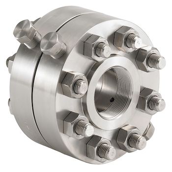

ORIFICE FLANGE
ORIFICE FLANGE DEFINED

Material Grades, Dimensions, and Shapes
Orifice flanges are available in all ASTM forged grades (ASTM A105, ASTM A350, ASTM A694, ASTM 182 respectively for carbon, alloy and, stainless steel flanges), dimensions (combinations of nominal sizes and pressure ratings) and, in socket weld, threaded or weld neck shape (WN is the most used). More details about these subjects are given below.
HOW AN ORIFICE FLANGE WORKS
An orifice flange functions as a crucial part of an orifice metering system, which is extensively used to measure the flow rate of fluids in pipelines. This system employs the principle of differential pressure measurement to determine the velocity and volumetric flow rate of the fluid passing through the pipe. Here’s a detailed explanation of how an orifice flange works:
Installation and Setup
The orifice flange is installed in pairs around an orifice plate, which is a precisely machined disk with a sharp-edged hole in the center. This assembly is mounted between two sections of a pipeline. The orifice plate’s diameter is smaller than that of the pipe, creating a constriction in the flow path.
Flow Through the Orifice Plate
As fluid (either liquid or gas) flows through the pipeline, it must pass through the smaller opening of the orifice plate. This causes the fluid to accelerate at the orifice, leading to a decrease in pressure across the plate. The pressure is higher upstream of the orifice plate (at the inlet side) and lower downstream (at the outlet side). This pressure drop is created by the energy conversion that occurs when the fluid’s velocity increases at the constriction, by the Bernoulli Principle.
Pressure Measurement
The orifice flanges are equipped with pressure taps, which are small openings that allow the system to measure the fluid pressure at two points: immediately before and after the orifice plate. These taps are connected to a differential pressure measuring instrument, such as a manometer, pressure transducer, or differential pressure transmitter. The difference in pressure readings, known as the differential pressure, is directly related to the flow rate of the fluid through the pipeline.
Calculating Flow Rate
The flow rate of the fluid can be calculated using the differential pressure measurement along with the orifice plate’s dimensions and the fluid’s properties. The calculation employs a formula derived from the Bernoulli Equation and the Continuity Equation, incorporating factors such as the orifice coefficient (which accounts for losses and deviations from ideal flow conditions) and the fluid density. The result provides an accurate measurement of the fluid’s flow rate through the pipe.
TYPES OF ORIFICE FLANGES
As discussed, orifice flanges are specialized flanges used in conjunction with orifice meters to measure the flow rate of fluids through pipelines. These flanges facilitate the installation of an orifice plate, which is a primary flow element that creates a pressure drop to determine the flow rate.
The design and type of orifice flanges play a crucial role in ensuring accurate measurements, ease of maintenance, and reliable operation of the flow metering system. Here’s an in-depth look at the main types of orifice flanges:
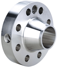
1. Weld Neck Orifice Flanges
Weld neck orifice flanges are characterized by their long, tapered neck that gradually transitions into the diameter of the pipeline. This design provides a strong, durable connection that can withstand high stresses, making weld neck orifice flanges suitable for high-pressure and high-temperature applications.
Features: The neck provides reinforcement that reduces stress concentrations at the base of the flange. The bore of the flange matches the inside diameter of the pipe, ensuring smooth flow and minimizing turbulence at the orifice plate.
Applications: Commonly used in critical and severe service applications where reliability and performance are paramount, such as in petrochemical plants, refineries, and power generation facilities.
2. Slip-On Orifice Flanges
Slip-on orifice flanges are designed to slide over the pipe and then be welded at the flange’s hub to secure it in place. They are simpler in design and lighter in weight compared to weld neck orifice flanges, making them a cost-effective option for lower-pressure applications.
Features: The installation of slip-on flanges is relatively easier due to their simple slip-on design. However, their strength under high pressure and temperature is not as robust as that of weld neck flanges.
Applications: Suitable for moderate conditions where ease of installation and cost are significant considerations, such as water distribution systems and non-critical process lines.
3. Socket Weld Orifice Flanges
Socket weld orifice flanges are intended for smaller pipe diameters and high-pressure applications. The pipe is inserted into the socket end of the flange and welded, providing a smooth bore and enhanced fluid flow.
Features: These flanges offer good strength and are less prone to leakage than slip-on flanges, making them ideal for smaller, high-pressure pipelines.
Applications: Frequently used in chemical processing, small-diameter high-pressure lines, and steam distribution systems.
4. Threaded Orifice Flanges
Threaded orifice flanges, also known as screwed orifice flanges, are designed for applications where welding is not suitable. The pipe threads directly into the flange, facilitating a quick and easy connection without the need for welding.
Features: These flanges can be easily installed and removed, offering a convenient solution for maintenance and assembly. However, their pressure and temperature capabilities are limited compared to welded flanges.
Applications: Ideal for low-pressure and non-critical applications, especially in areas where welding poses safety risks, such as explosive environments.
5. Ring-Type Joint (RTJ) Orifice Flanges
RTJ orifice flanges are used in high-pressure and high-temperature applications. They feature a grooved face that accommodates a metal ring gasket for a tight, leak-proof seal.
Features: The metal ring gasket provides a highly reliable seal under extreme conditions, ensuring the integrity of the flange connection.
Applications: Commonly used in the oil and gas industry, particularly in high-pressure pipelines and offshore platforms.
5. Corner-Tap Orifice Flanges
A corner tap orifice flange is a specific configuration used in the flow measurement of fluids, where the pressure taps are located directly at the orifice plate’s edges.Key Characteristics:
- Pressure Tap Placement: The distinctive feature of corner tap orifice flanges is the placement of pressure taps. Unlike flange taps, which are drilled through the flange some distance away from the orifice plate, or vena contracta and pipe taps, which are placed at specific locations along the pipe, corner taps are located at the corners of the orifice plate, providing an immediate pressure differential reading.
- Orifice Plate Interface: The pressure taps in a corner tap arrangement closely interface with the orifice plate, intended to measure the pressure drop across the plate accurately.
Applications and Considerations:
- Fluid Characteristics: Corner tap orifice flanges are typically used for clean liquids or gases. The proximity of the taps to the orifice plate makes this configuration less suitable for slurries or fluids with particulate matter that might clog the taps.
- Measurement Accuracy: The corner tap configuration can offer high accuracy for flow measurement under certain conditions, particularly in smaller pipe sizes where the flow profile is well-developed and predictable.
- Installation and Maintenance: Due to their placement, corner taps may be more challenging to install and maintain compared to other tap configurations. It’s crucial to ensure that the taps do not become clogged and that they accurately reflect the pressure differential across the orifice plate.
Advantages and Limitations:
- Advantages: Corner taps can provide accurate measurements for certain applications and are particularly effective in systems with well-characterized fluid dynamics and in pipes with smaller diameters.
- Limitations: Their application is generally limited by the fluid type and by operational conditions that favor other tap configurations for better accuracy or ease of maintenance. The risk of tap blockage by particulates in the fluid can also be a concern.
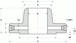
ORIFICE FLANGE DIMENSIONS ASME B16.36
Notes for data shown in tables:
- Dimensions are in millimeters (excluding bolts and bolt holes).
- Different NPT sizes than 1/2 are available
- Bolt lengths for RF flanges include an allowance for orifice and gasket thickness of 6 mm (0.25 in.) for NPS 1 to NPS 12. Bolt lengths for ring-type joint flanges include the allowance of 15 mm (0.62 in.) for NPS 1 to NPS 3.
- Bore (B) has to be specified by the buyer
- Stud Bolt lengths excl. the height of the chamfers
WELD NECK RF, CLASS 300
| NPS | A | R | O | T | H | X | Tg |
| 1 | 33.4 | 50.8 | 125 | 36.6 | 81 | 54 | 6.4 |
| 1½ | 48.3 | 73 | 155 | 36.6 | 84 | 70 | 6.4 |
| 2 | 60.3 | 92.1 | 165 | 36.6 | 84 | 84 | 6.4 |
| 2½ | 73 | 104.8 | 190 | 36.6 | 87 | 100 | 6.4 |
| 3 | 88.9 | 127 | 210 | 36.6 | 87 | 117 | 9.5 |
| 4 | 114.3 | 157.2 | 255 | 36.6 | 90 | 146 | 12.7 |
| 6 | 168.3 | 215.9 | 320 | 36.6 | 98 | 206 | 12.7 |
| 8 | 219.1 | 269.9 | 380 | 39.7 | 110 | 260 | 12.7 |
| 10 | 273 | 323.8 | 445 | 46.1 | 116 | 321 | 12.7 |
| 12 | 323.8 | 381 | 520 | 49.3 | 129 | 375 | 12.7 |
| 14 | 355.6 | 412.8 | 585 | 52.4 | 141 | 425 | 12.7 |
| 16 | 406.4 | 469.9 | 650 | 55.6 | 144 | 483 | 12.7 |
| 18 | 457 | 533.4 | 710 | 58.8 | 157 | 533 | 12.7 |
| 20 | 508 | 584.2 | 775 | 62 | 160 | 587 | 12.7 |
| 24 | 610 | 692.2 | 915 | 68.3 | 167 | 702 | 12.7 |
| NPS | Bolt Diameter | # Bolts | Bolt holes diameter | Bolts Diameter | Bolts length mm. |
| 1 | 88.9 | 4 | 11/16 | 5/8 | 125 |
| 1½ | 114.3 | 4 | 13/16 | 3/4 | 135 |
| 2 | 127 | 8 | 11/16 | 5/8 | 125 |
| 2½ | 149.2 | 8 | 13/16 | 3/4 | 135 |
| 3 | 168.3 | 8 | 13/16 | 3/4 | 135 |
| 4 | 200 | 8 | 13/16 | 3/4 | 135 |
| 6 | 269.9 | 12 | 7/8 | 3/4 | 135 |
| 8 | 330.2 | 12 | 1 | 7/8 | 145 |
| 10 | 387.4 | 16 | 1 1/8 | 1 | 165 |
| 12 | 450.8 | 16 | 1¼ | 1 1/8 | 180 |
| 14 | 514.4 | 20 | 1¼ | 1 1/8 | 185 |
| 16 | 571.5 | 20 | 1 3/8 | 1¼ | 195 |
| 18 | 628.6 | 24 | 1 3/8 | 1¼ | 205 |
| 20 | 685.8 | 24 | 1 3/8 | 1¼ | 215 |
| 24 | 812.8 | 24 | 1 3/8 | 1½ | 240 |
COMMENTS: The height of Raised Face (RF) in CLASS 300 is 2 mm
WELD NECK RF, CLASS 600
| NPS | A | R | O | T | H | X | Tg |
| 1 | 33.5 | 50.8 | 125 | 36.6 | 81 | 54 | 6.4 |
| 1½ | 48.3 | 73 | 155 | 36.6 | 84 | 70 | 6.4 |
| 2 | 60.3 | 92.1 | 165 | 36.6 | 84 | 84 | 6.4 |
| 2½ | 73 | 104.8 | 190 | 36.6 | 87 | 100 | 6.4 |
| 3 | 88.9 | 127 | 210 | 36.6 | 87 | 117 | 9.5 |
| 4 | 114.3 | 157.2 | 275 | 38.1 | 102 | 152 | 12.7 |
| 6 | 168.3 | 215.9 | 355 | 47.7 | 117 | 222 | 12.7 |
| 8 | 219.1 | 269.9 | 420 | 55.6 | 133 | 273 | 12.7 |
| 10 | 273 | 323.8 | 510 | 63.5 | 152 | 343 | 12.7 |
| 12 | 323.8 | 381 | 560 | 66.7 | 156 | 400 | 12.7 |
| 14 | 355.6 | 412.8 | 605 | 69.9 | 165 | 432 | 12.7 |
| 16 | 406.4 | 469.9 | 685 | 76.2 | 178 | 495 | 12.7 |
| 18 | 457.2 | 533.4 | 745 | 82.6 | 184 | 546 | 12.7 |
| 20 | 508 | 584.2 | 815 | 88.9 | 190 | 610 | 12.7 |
| 24 | 609.6 | 692.2 | 940 | 101.6 | 203 | 718 | 12.7 |
| NPS | BOLT CIRCLE DIAM. | BOLTS # | HOLES DIAM. | BOLTS DIAMETER | BOLTS LENGTH |
| 1 | 88.9 | 4 | 11/16 | 5/8 | 125 |
| 1½ | 114.3 | 4 | 13/16 | 3/4 | 135 |
| 2 | 127 | 8 | 11/16 | 5/8 | 125 |
| 2½ | 149.2 | 8 | 13/16 | 3/4 | 135 |
| 3 | 168.3 | 8 | 13/16 | 3/4 | 135 |
| 4 | 215.9 | 8 | 1 | 7/8 | 150 |
| 6 | 292.1 | 12 | 1 1/8 | 1 | 180 |
| 8 | 349.2 | 12 | 1¼ | 1 1/8 | 195 |
| 10 | 431.8 | 16 | 1 3/8 | 1¼ | 220 |
| 12 | 489 | 20 | 1 3/8 | 1¼ | 230 |
| 14 | 527 | 20 | 1½ | 1 3/8 | 240 |
| 16 | 603.2 | 20 | 1 5/8 | 1½ | 260 |
| 18 | 654 | 20 | 1 3/4 | 1 5/8 | 280 |
| 20 | 723.9 | 24 | 1 3/4 | 1 5/8 | 300 |
| 24 | 838.2 | 24 | 2 | 1 5/8 | 335 |
COMMENTS: The height of Raised Face (RF) in CLASS 600 is 2 mm at NPS 1 – NPS 3, and 7 mm at NPS 4 – NPS 24.
WELD NECK RF, CLASS 900
| NPS | R | O | T | H | X | A | Tg |
| 1 | 50.8 | 125 | 36.6 | 81 | 54 | 33.5 | 6.4 |
| 1½ | 73 | 155 | 36.6 | 84 | 70 | 48.3 | 6.4 |
| 2 | 92.1 | 165 | 36.6 | 84 | 84 | 60.3 | 6.4 |
| 2½ | 104.8 | 190 | 36.6 | 87 | 100 | 73 | 6.4 |
| 3 | 127 | 240 | 38.1 | 102 | 127 | 88.9 | 9.5 |
| 4 | 157.2 | 290 | 44.5 | 114 | 159 | 114.3 | 12.7 |
| 6 | 215.9 | 380 | 55.6 | 140 | 235 | 168.3 | 12.7 |
| 8 | 269.9 | 470 | 63.5 | 162 | 298 | 219.1 | 12.7 |
| 10 | 323.8 | 545 | 69.9 | 184 | 368 | 273 | 12.7 |
| 12 | 381 | 610 | 79.4 | 200 | 419 | 323.8 | 12.7 |
| 14 | 412.8 | 640 | 85.8 | 213 | 451 | 355.6 | 12.7 |
| 16 | 469.9 | 705 | 88.9 | 216 | 508 | 406.4 | 12.7 |
| 18 | 533.4 | 785 | 101.6 | 229 | 565 | 457.2 | 12.7 |
| 20 | 584.2 | 855 | 108 | 248 | 622 | 508 | 12.7 |
| 24 | 692.2 | 1040 | 139.7 | 292 | 749 | 609.6 | 12.7 |
| NPS | BOLT CIRCLE DIAM. | BOLTS # | HOLES DIAM. | BOLTS DIAMETER | BOLTS LENGTH |
| 1 | 88.9 | 4 | 11/16 | 5/8 | 125 |
| 1½ | 114.3 | 4 | 13/16 | 3/4 | 135 |
| 2 | 127 | 8 | 11/16 | 5/8 | 125 |
| 2½ | 149.2 | 8 | 13/16 | 3/4 | 135 |
| 3 | 190.5 | 8 | 1 | 7/8 | 150 |
| 4 | 235 | 8 | 1¼ | 1 1/8 | 180 |
| 6 | 317.5 | 12 | 1¼ | 1 1/8 | 195 |
| 8 | 393.7 | 12 | 1½ | 1 3/8 | 230 |
| 10 | 469.9 | 16 | 1½ | 1 3/8 | 240 |
| 12 | 533.4 | 20 | 1½ | 1 3/8 | 260 |
| 14 | 558.8 | 20 | 1 5/8 | 1½ | 280 |
| 16 | 616 | 20 | 1 3/4 | 1 5/8 | 290 |
| 18 | 685.8 | 20 | 2 | 1 7/8 | 330 |
| 20 | 749.3 | 20 | 2 1/8 | 2 | 355 |
| 24 | 901.7 | 20 | 2 1/8 | 2½ | 445 |
COMMENTS: The height of Raised Face (RF) in CLASS 900 is 7 mm.
WELD NECK RF, CLASS 1500
| NPS | R | O | T | H | X | A | Tg |
| 1 | 50.8 | 150 | 38.1 | 83 | 52 | 33.5 | 6.4 |
| 1½ | 73 | 180 | 38.1 | 89 | 70 | 48.3 | 6.4 |
| 2 | 92.1 | 215 | 38.1 | 102 | 105 | 60.3 | 6.4 |
| 2½ | 104.8 | 245 | 41.3 | 105 | 124 | 73 | 6.4 |
| 3 | 127 | 265 | 47.7 | 117 | 133 | 88.9 | 9.5 |
| 4 | 157.2 | 310 | 54 | 124 | 162 | 114.3 | 12.7 |
| 6 | 215.9 | 395 | 82.6 | 171 | 229 | 168.3 | 12.7 |
| 8 | 269.9 | 485 | 92.1 | 213 | 292 | 219.1 | 12.7 |
| 10 | 323.8 | 585 | 108 | 254 | 368 | 273 | 12.7 |
| 12 | 381 | 675 | 123.9 | 283 | 451 | 323.8 | 12.7 |
| 14 | 412.8 | 750 | 133.4 | 298 | 495 | 355.6 | 12.7 |
| 16 | 469.9 | 825 | 146.1 | 311 | 552 | 406.4 | 12.7 |
| 18 | 533.4 | 915 | 162 | 327 | 597 | 457.2 | 12.7 |
| 20 | 584.2 | 985 | 177.8 | 356 | 641 | 508 | 12.7 |
| 24 | 692.2 | 1170 | 203.2 | 406 | 762 | 609.6 | 12.7 |
| NPS | BOLT CIRCLE DIAM. | BOLTS # | HOLES DIAM. | BOLTS DIAMETER | BOLTS LENGTH |
| 1 | 101.6 | 4 | 1 | 7/8 | 150 |
| 1½ | 123.8 | 4 | 1 1/8 | 1¼ | 160 |
| 2 | 165.1 | 8 | 1 | 7/8 | 150 |
| 2½ | 190.5 | 8 | 1 1/8 | 1 | 165 |
| 3 | 203.2 | 8 | 1¼ | 1 1/8 | 185 |
| 4 | 241.3 | 8 | 1 3/8 | 1¼ | 205 |
| 6 | 317.5 | 12 | 1½ | 1 3/8 | 265 |
| 8 | 393.7 | 12 | 1 3/4 | 1 5/8 | 300 |
| 10 | 482.6 | 12 | 2 | 1 7/8 | 345 |
| 12 | 571.6 | 16 | 2 1/8 | 2 | 380 |
| 14 | 635 | 16 | 2 3/8 | 2¼ | 415 |
| 16 | 704.8 | 16 | 2 5/8 | 2½ | 450 |
| 18 | 774.7 | 16 | 2 7/8 | 2 3/4 | 500 |
| 20 | 831.8 | 16 | 3 1/8 | 3 | 545 |
| 24 | 990.6 | 16 | 3 5/8 | 3½ | 620 |
COMMENTS: The height of Raised Face (RF) in CLASS 1500 is 7 mm
WELD NECK RF, CLASS 2500
| NPS | R | O | T | H | X | A | Tg |
| 1 | 50.8 | 160 | 38.1 | 92 | 57 | 33.5 | 6.4 |
| 1½ | 73 | 205 | 44.5 | 111 | 79 | 48.3 | 6.4 |
| 2 | 92.1 | 235 | 50.8 | 127 | 95 | 60.3 | 6.4 |
| 2½ | 104.8 | 265 | 57.2 | 143 | 114 | 73 | 6.4 |
| 3 | 127 | 305 | 66.7 | 168 | 133 | 88.9 | 9.5 |
| 4 | 157.2 | 355 | 76.2 | 190 | 165 | 114.3 | 12.7 |
| 6 | 215.9 | 485 | 108 | 273 | 235 | 168.3 | 12.7 |
| 8 | 269.9 | 550 | 127 | 318 | 305 | 219.1 | 12.7 |
| 10 | 323.8 | 675 | 165.1 | 419 | 375 | 273 | 12.7 |
| 12 | 381 | 760 | 184.2 | 464 | 441 | 323.8 | 12.7 |
| NPS | BOLT CIRCLE DIAM. | BOLTS # | HOLES DIAM. | BOLTS DIAMETER | BOLTS LENGTH |
| 1 | 108 | 4 | 1 | 7/8 | 150 |
| 1½ | 146 | 4 | 1¼ | 1 1/8 | 180 |
| 2 | 171.4 | 8 | 1 1/8 | 1 | 185 |
| 2½ | 196.8 | 8 | 1¼ | 1 1/8 | 205 |
| 3 | 228.6 | 8 | 1 3/8 | 1¼ | 230 |
| 4 | 273 | 8 | 1 5/8 | 1½ | 260 |
| 6 | 368.3 | 8 | 2 1/8 | 2 | 350 |
| 8 | 438.2 | 12 | 2 1/8 | 2 | 385 |
| 10 | 539.8 | 12 | 2 5/8 | 2½ | 490 |
| 12 | 619.1 | 12 | 2 7/8 | 2 3/4 | 540 |
COMMENTS: The height of Raised Face (RF) in CLASS 2500 is 7 mm.
WELD NECK RTJ, CLASS 600

| NPS | O | T | H | GROOVE # | P | E |
| 1 | 125 | 36.6 | 81 | R16 | 50.8 | 6.35 |
| 1½ | 155 | 36.6 | 84 | R20 | 68.27 | 6.35 |
| 2 | 165 | 36.6 | 84 | R23 | 82.55 | 7.92 |
| 2½ | 190 | 36.6 | 87 | R26 | 101.6 | 7.92 |
| 3 | 210 | 36.6 | 87 | R31 | 123.83 | 7.92 |
| 4 | 275 | 38.1 | 102 | R37 | 149.23 | 7.92 |
| 6 | 355 | 47.7 | 117 | R45 | 211.12 | 7.92 |
| 8 | 420 | 55.6 | 133 | R49 | 269.88 | 7.92 |
| 10 | 510 | 63.5 | 152 | R53 | 323.85 | 7.92 |
| 12 | 560 | 66.7 | 156 | R57 | 381 | 7.92 |
| 14 | 605 | 69.9 | 165 | R61 | 419.1 | 7.92 |
| 16 | 685 | 76.2 | 178 | R65 | 469.9 | 7.92 |
| 18 | 745 | 82.6 | 184 | R69 | 533.4 | 7.92 |
| 20 | 815 | 88.9 | 190 | R73 | 584.2 | 9.53 |
| 24 | 940 | 101.6 | 203 | R77 | 692.15 | 11.13 |
| NPS | F | R | W | X | A | Tg |
| 1 | 8.74 | 0.8 | 25.4 | 54 | 33.5 | 6.4 |
| 1½ | 8.74 | 0.8 | 25.4 | 70 | 48.3 | 6.4 |
| 2 | 11.91 | 0.8 | 27 | 84 | 60.3 | 6.4 |
| 2½ | 11.91 | 0.8 | 27 | 100 | 73 | 6.4 |
| 3 | 11.91 | 0.8 | 27 | 117 | 88.9 | 9.5 |
| 4 | 11.91 | 0.8 | 27 | 152 | 114.3 | 12.7 |
| 6 | 11.91 | 0.8 | 27 | 222 | 168.3 | 12.7 |
| 8 | 11.91 | 0.8 | 27 | 273 | 219.1 | 12.7 |
| 10 | 11.91 | 0.8 | 27 | 343 | 273 | 12.7 |
| 12 | 11.91 | 0.8 | 27 | 400 | 323.8 | 12.7 |
| 14 | 11.91 | 0.8 | 27 | 432 | 355.6 | 12.7 |
| 16 | 11.91 | 0.8 | 30.2 | 495 | 406.4 | 12.7 |
| 18 | 11.91 | 0.8 | 30.2 | 546 | 457.2 | 12.7 |
| 20 | 13.49 | 1.5 | 31.8 | 610 | 508 | 12.7 |
| 24 | 16.66 | 1.5 | 36.5 | 718 | 609.6 | 12.7 |
WELD NECK RTJ, CLASS 900
| NPS | O | T | H | GROOVE # | P | E |
| 1 | 125 | 36.6 | 81 | R16 | 50.8 | 6.35 |
| 1½ | 155 | 36.6 | 84 | R20 | 68.27 | 6.35 |
| 2 | 165 | 36.6 | 84 | R23 | 82.55 | 7.92 |
| 2½ | 190 | 36.6 | 87 | R26 | 101.6 | 7.92 |
| 3 | 240 | 38.1 | 102 | R31 | 123.83 | 7.92 |
| 4 | 290 | 44.5 | 114 | R37 | 149.23 | 7.92 |
| 6 | 380 | 55.6 | 140 | R45 | 211.12 | 7.92 |
| 8 | 470 | 63.5 | 162 | R49 | 269.88 | 7.92 |
| 10 | 545 | 69.9 | 184 | R53 | 323.85 | 7.92 |
| 12 | 610 | 79.4 | 200 | R57 | 381 | 7.92 |
| 14 | 640 | 85.8 | 213 | R62 | 419.1 | 11.13 |
| 16 | 705 | 88.9 | 216 | R66 | 469.9 | 11.13 |
| 18 | 785 | 101.6 | 229 | R70 | 533.4 | 12.7 |
| 20 | 855 | 108 | 248 | R74 | 584.2 | 12.7 |
| 24 | 1040 | 139.7 | 292 | R78 | 692.15 | 15.88 |
| NPS | F | R | W | X | A | Tg |
| 1 | 8.74 | 0.8 | 25.4 | 54 | 33.5 | 6.4 |
| 1½ | 8.74 | 0.8 | 25.4 | 70 | 48.3 | 6.4 |
| 2 | 11.91 | 0.8 | 27 | 84 | 60.3 | 6.4 |
| 2½ | 11.91 | 0.8 | 27 | 100 | 73 | 6.4 |
| 3 | 11.91 | 0.8 | 27 | 127 | 88.9 | 9.5 |
| 4 | 11.91 | 0.8 | 27 | 159 | 114.3 | 12.7 |
| 6 | 11.91 | 0.8 | 27 | 235 | 168.3 | 12.7 |
| 8 | 11.91 | 0.8 | 27 | 298 | 219.1 | 12.7 |
| 10 | 11.91 | 0.8 | 27 | 368 | 273 | 12.7 |
| 12 | 11.91 | 0.8 | 27 | 419 | 323.8 | 12.7 |
| 14 | 16.66 | 1.5 | 33.3 | 451 | 355.6 | 12.7 |
| 16 | 16.66 | 1.5 | 36.5 | 508 | 406.4 | 12.7 |
| 18 | 19.84 | 1.5 | 39.7 | 565 | 457.2 | 12.7 |
| 20 | 19.84 | 1.5 | 39.7 | 622 | 508 | 12.7 |
| 24 | 26.97 | 2.4 | 47.6 | 749 | 609.6 | 12.7 |
WELD NECK RTJ, CLASS 1500
| NPS | O | T | H | GROOVE # | P | E |
| 1 | 150 | 38.1 | 83 | R16 | 50.8 | 6.35 |
| 1½ | 180 | 38.1 | 89 | R20 | 68.27 | 6.35 |
| 2 | 215 | 38.1 | 102 | R24 | 95.25 | 7.92 |
| 2½ | 245 | 41.3 | 105 | R27 | 107.95 | 7.92 |
| 3 | 265 | 47.7 | 117 | R35 | 136.53 | 7.92 |
| 4 | 310 | 54 | 124 | R39 | 161.93 | 7.92 |
| 6 | 395 | 82.6 | 171 | R46 | 211.14 | 9.52 |
| 8 | 485 | 92.1 | 213 | R50 | 269.88 | 11.13 |
| 10 | 585 | 108 | 254 | R54 | 323.85 | 11.13 |
| 12 | 675 | 123.9 | 283 | R58 | 381 | 14.27 |
| 14 | 750 | 133.4 | 298 | R63 | 419.1 | 15.88 |
| 16 | 825 | 146.1 | 311 | R67 | 469.9 | 17.48 |
| 18 | 915 | 162 | 327 | R71 | 533.4 | 17.48 |
| 20 | 985 | 177.8 | 356 | R75 | 584.2 | 17.48 |
| 24 | 1170 | 203.2 | 406 | R79 | 692.15 | 20.62 |
| NPS | F | R | W | X | A | Tg |
| 1 | 8.74 | 0.8 | 25.4 | 52 | 33.5 | 6.4 |
| 1½ | 8.74 | 0.8 | 25.4 | 70 | 48.3 | 6.4 |
| 2 | 11.91 | 0.8 | 27 | 105 | 60.3 | 6.4 |
| 2½ | 11.91 | 0.8 | 27 | 124 | 73 | 6.4 |
| 3 | 11.91 | 0.8 | 27 | 133 | 88.9 | 9.5 |
| 4 | 11.91 | 0.8 | 27 | 162 | 114.3 | 12.7 |
| 6 | 13.49 | 1.5 | 28.6 | 229 | 168.3 | 12.7 |
| 8 | 16.66 | 1.5 | 33.3 | 292 | 219.1 | 12.7 |
| 10 | 16.66 | 1.5 | 33.3 | 368 | 273 | 12.7 |
| 12 | 23.01 | 1.5 | 39.7 | 451 | 323.8 | 12.7 |
| 14 | 26.97 | 2.4 | 44.4 | 495 | 355.6 | 12.7 |
| 16 | 30.18 | 2.4 | 50.8 | 552 | 406.4 | 12.7 |
| 18 | 30.18 | 2.4 | 50.8 | 597 | 457.2 | 12.7 |
| 20 | 33.32 | 2.4 | 54 | 641 | 508 | 12.7 |
| 24 | 36.53 | 2.4 | 58.7 | 762 | 609.6 | 12.7 |
WELD NECK RTJ, CLASS 2500 RTJ
| 2500# | T | H | GROOVE # | P | E | |
| 1 | 160 | 38.1 | 92 | R18 | 60.33 | 6.35 |
| 1½ | 205 | 44.5 | 111 | R23 | 82.55 | 7.92 |
| 2 | 235 | 50.8 | 127 | R26 | 101.6 | 7.92 |
| 2½ | 265 | 57.2 | 143 | R28 | 111.13 | 9.53 |
| 3 | 305 | 66.7 | 168 | R32 | 127 | 9.53 |
| 4 | 355 | 76.2 | 190 | R38 | 157.18 | 11.13 |
| 6 | 485 | 108 | 273 | R47 | 228.6 | 12.7 |
| 8 | 550 | 127 | 318 | R51 | 279.4 | 14.27 |
| 10 | 675 | 165.1 | 419 | R55 | 342.9 | 17.48 |
| 12 | 760 | 184.2 | 464 | R60 | 406.4 | 17.48 |
| 2500# | F | R | W | X | A | Tg |
| 1 | 8.74 | 0.8 | 25.4 | 57 | 33.5 | 6.4 |
| 1½ | 11.91 | 0.8 | 27 | 79 | 48.3 | 6.4 |
| 2 | 11.91 | 0.8 | 27 | 95 | 60.3 | 6.4 |
| 2½ | 13.49 | 1.5 | 30.2 | 114 | 73 | 6.4 |
| 3 | 13.49 | 1.5 | 30.2 | 133 | 88.9 | 9.5 |
| 4 | 16.66 | 1.5 | 33.3 | 165 | 114.3 | 12.7 |
| 6 | 19.84 | 1.5 | 36.5 | 235 | 168.3 | 12.7 |
| 8 | 23.01 | 1.5 | 39.7 | 305 | 219.1 | 12.7 |
| 10 | 30.18 | 2.4 | 47.6 | 375 | 273 | 12.7 |
| 12 | 33.32 | 2.4 | 50.8 | 441 | 323.8 | 12.7 |


One Response
Dear Sir
Good day.
Kindly quote your best price for supplying orifice flange shown in attached file CIF Alexandria, Egypt. Quotation due date Apr 6.