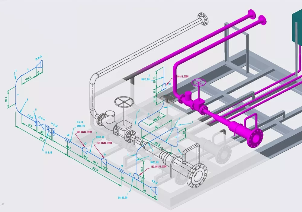
Piping isometrics are a type of technical drawing used in the engineering and piping industries to depict three-dimensional piping systems in a two-dimensional format. These drawings are critical for the design, construction, and maintenance of piping systems, providing detailed information about the size, shape, and route of pipes, as well as their connections, fittings, and valves.
PIPING ISOMETRICS
Piping isometrics are detailed drawings that provide a three-dimensional representation of the piping system, including all the necessary information for fabrication and installation.
In the world of industrial projects, precision and accuracy are of utmost importance. Any errors or miscalculations can lead to costly delays, safety hazards, and even catastrophic failures. This is where piping isometrics come into play.
KEY FEATURES OF ISOMETRIC DRAWINGS
Three-Dimensional Representation: Despite being presented on a two-dimensional plane, isometric drawings offer a three-dimensional view of the piping system, which helps in understanding the layout and spatial relationships between different components.
Scale: Piping isometrics are not usually drawn to scale, but dimensions are clearly indicated to provide accurate information on lengths and sizes.
Detailing: These drawings include comprehensive details such as the specifications of pipes (diameter, material, and schedule), types of fittings (elbows, tees, reducers), and the location of valves and instrumentation. This information is crucial for fabrication, installation, and inspection.
Orientation: The isometric view allows the depiction of the system in a way that dimensions along all three axes (X, Y, and Z) can be represented accurately, facilitating easier visualization of complex arrangements.
Simplification: Symbols and conventions are used to represent various piping components and connections, simplifying the drawing while conveying full information.
IMPORTANCE OF ISOMETRICS
The drawing of accurate isometrics during the engineering phase of a piping system is important for a multitude of reasons:
- Conceptualization of the piping system: isometrics allow for accurate visualization of the entire piping system and for optimization of the design choices.
Fabrication and Assembly: By providing a three-dimensional representation, these drawings enable engineers, designers, and fabricators to have a clear understanding of how the pipes will be laid out and interconnected at the installation field (green or brown). If fabrication works are necessary (for example cutting and bending of pipes), isometrics provide guidance to the Fabricators involved in the project. The isometric visualization of the piping system is essential for identifying any potential clashes or interferences with other equipment or structures, ensuring that the piping system can be installed without issues.
Material Quantification: They help in estimating the quantity and the quality of the materials needed to implement the conceived piping system, including pipes, fittings, and valves, which is essential for cost estimation and procurement. Piping isometrics also provide vital information about the dimensions and the technical specifications of the pipes. These drawings include details such as pipe sizes, lengths, angles, and bends, as well as the location of valves, fittings, and supports.
Troubleshooting and Maintenance: Isometric drawings are invaluable for maintenance personnel to identify parts, understand the piping layout, and address issues efficiently.
Coordination and Planning: In complex projects involving multiple engineering disciplines, piping isometrics facilitate coordination by clearly illustrating how piping systems integrate with the overall plant design.
- Reduction of cost of poor quality: with the help of accurate isometrics, all activities can proceed smoothly and the chances for costly errors are reduced
- Optimize the safety of the piping system: by accurately representing the layout and dimensions of the pipes, these drawings allow engineers to assess the structural integrity of the system. They can identify potential stress points, evaluate the need for additional supports or reinforcements, and ensure that the system can withstand the required pressure and temperature conditions. This proactive approach to safety helps to prevent accidents, leaks, and failures, ultimately protecting both the workers and the environment.
Another significant advantage of piping isometrics is that they serve as a communication tool between different stakeholders involved in the project. These drawings act as a common language that can be easily understood by engineers, designers, fabricators, and construction teams. By providing a visual representation and clear specifications, piping isometrics ensure that everyone involved in the project is on the same page. This helps to minimize misunderstandings, improve collaboration, and ultimately enhance the overall efficiency of the project.
In conclusion, piping isometrics are an essential component of engineering projects, especially when they relate to piping systems.
CHALLENGES IN MAKING ISOMETRICS
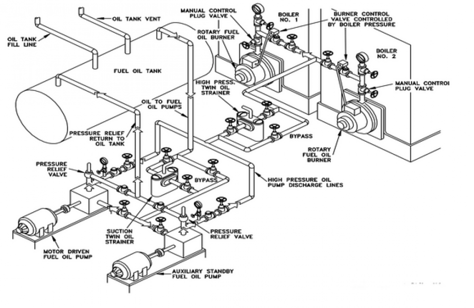
Piping Isometrics are an essential part of the design and construction process in the field of engineering. They provide a detailed representation of the piping system, including all the necessary dimensions, angles, and connections. However, creating accurate piping isometrics can be a challenging task, as there are several common challenges that engineers often face.
Complexity of the piping system
One of the most common challenges in creating accurate piping isometrics is the complexity of the piping system itself. Piping systems can be intricated and involve numerous components, such as valves, fittings, and supports. Each component needs to be accurately represented in the isometric drawing, which requires a deep understanding of the system and its various elements. Additionally, piping design engineers must ensure that all the dimensions and angles are correctly measured and depicted in the drawing.
Coordination of multiple disciplines
Another challenge in creating accurate piping isometrics is the coordination between different disciplines. In large-scale projects, multiple disciplines, such as mechanical, electrical, and civil engineering, are involved in the design and construction process. Each discipline has its own set of requirements and specifications that need to be incorporated into the piping isometrics. This coordination can be a complex task, as it requires effective communication and collaboration between the different disciplines to ensure that all the necessary information is accurately represented in the isometric drawing.
Availability of design data
Furthermore, the accuracy of the piping isometrics can be affected by the availability and quality of the design data. In some cases, the design data may be incomplete or outdated, which can lead to errors and inaccuracies in the isometric drawing. Engineers must have access to accurate and up-to-date design data to ensure the accuracy of the piping isometrics. This may require close collaboration with other team members, such as designers and drafters, to ensure that all the necessary information is available and incorporated into the drawing.
The learning curve of piping design software
Another challenge in creating accurate piping isometrics is the use of software and technology. While technology has greatly improved the efficiency and accuracy of the design process, it also presents its own set of challenges. Engineers need to be proficient in using the software and technology to create accurate piping isometrics. This may require additional training and expertise to ensure that the software is used correctly and that all the necessary information is accurately represented in the drawing.
Consistency & Standardization
There are standardized symbols and notations for piping components; however, ensuring consistency across drawings and adherence to industry standards can be challenging. Also, isometric drawings are typically not to scale, which requires careful dimensioning to ensure that the drawn dimensions accurately represent the physical piping system.
Regulatory Challenges
Adhering to all the relevant codes, standards, and regulations governing piping systems is essential and can add complexity to the drawing process. Remarkable knowledge is necessary, and such knowledge shall be kept up to date given the possible changes in specifications and regulatory requirements. Piping isometrics must also consider safety aspects and Laws applicable at the site of installation, including access for maintenance, operation clearances, and the safe conveyance of fluids or gases.
In conclusion, creating accurate piping isometrics can be a challenging task due to various common challenges. Overcoming these challenges requires a deep understanding of the system, effective communication and collaboration between different disciplines, access to accurate and up-to-date design data, and proficiency in using software and technology. By addressing these challenges, engineers can ensure the accuracy and reliability of the piping isometrics, which is crucial for the successful design and construction of effective, safe, long-lasting piping systems.
HOW TO READ ISOMETRICS: BEST PRACTICE
Piping isometrics are crucial documents in the field of engineering and construction. They provide a detailed representation of the piping system, including its dimensions, connections, and components. However, reading and interpreting these isometrics can be a challenging task, especially for those who are new to the field. In this paragraph, we discuss some best practices for reading and interpreting piping isometrics.
Reading piping isometrics, which are detailed two-dimensional drawings representing three-dimensional piping systems, requires understanding specific symbols, conventions, and perspectives. Here’s a basic guide on how to read these essential engineering drawings:
1. Understand Isometric Projection
Recognize that the isometric drawing represents a 3D object on a 2D surface. Three axes (X, Y, and Z) are drawn at 120-degree angles to each other, providing a pseudo-3D view.
2. Identify Lines
Main Lines: Represent the main pipes, usually the thickest lines on the drawing.
Hidden Lines: Dashed lines indicating parts of the piping that are not visible in the current view.
Break Lines: Short, dashed lines showing where a pipe continues but is not drawn to scale.
3. Look for Symbols and Notations
Familiarize yourself with common symbols used for fittings (elbows, tees, reducers), valves (gate, globe, check), and other components (flanges, gaskets).
Note annotations for sizes, lengths, and angles. Pipe diameters, schedules (wall thickness), and material specifications are typically indicated.
4. Examine Dimensions
Study all dimensions noted on the drawing, including lengths between fittings and overall lengths of pipe runs. Dimensions are crucial for fabricating the piping system accurately.
5. Review Flow Direction
Arrows or notes may indicate the direction of flow through the piping system, which is essential for understanding the system’s operation.
6. Check for Details and Specifications
Look for detailed drawings or insets that provide closer views or cross-sections of complex areas.
Material specifications, pressure ratings, and insulation requirements are often noted alongside the relevant sections of piping.
7. Understand the Piping Codes
Symbols and abbreviations should be interpreted according to the standard piping codes used in the drawing, such as ANSI/ASME B31.3 for process piping.
8. Reference the Bill of Materials (BOM)
A BOM may be included, listing all components, materials, and quantities required for the piping system. This can be crucial for procurement and inventory management.
9. Coordinate with Other Drawings
Piping isometrics should be reviewed in conjunction with other project drawings, such as P&IDs (Piping and Instrumentation Diagrams) and layout drawings, to ensure a comprehensive understanding of the system’s integration within the overall project.
10. Consult Legends and Notes
Always check the drawing’s legend for specific meanings of symbols and abbreviations. Notes on the drawing may also provide critical information about installation, testing, and operation requirements.
DIFFERENCE BETWEEN PIPING ISOMETRICS AND P&ID DIAGRAMS
Piping Isometrics and Piping and Instrumentation Diagrams (P&ID) are both crucial in the design, construction, and operation of piping systems but serve different purposes and convey information in unique ways. Understanding the differences between these two types of drawings is essential for professionals in the engineering, construction, and process industries.
Piping Isometrics
- Three-Dimensional Representation: Piping isometrics provide a three-dimensional representation of piping systems on a two-dimensional surface. They are drawn to show the piping layout with its true dimensions as it would appear in reality but are not typically drawn to scale.
- Detail Orientation: These drawings are highly detailed, showing specific information about pipe lengths, diameters, fabrication details, and the exact orientation of all components, including fittings, valves, and flanges.
- Purpose: The primary purpose of piping isometrics is to facilitate the fabrication and installation of the piping system. They help in understanding how pipes run through a facility, including their bends, branches, and in-line components.
- No Process Information: While piping isometrics detail the physical attributes of the piping system, they generally do not include process information or operating parameters.
Piping and Instrumentation Diagrams (P&ID)
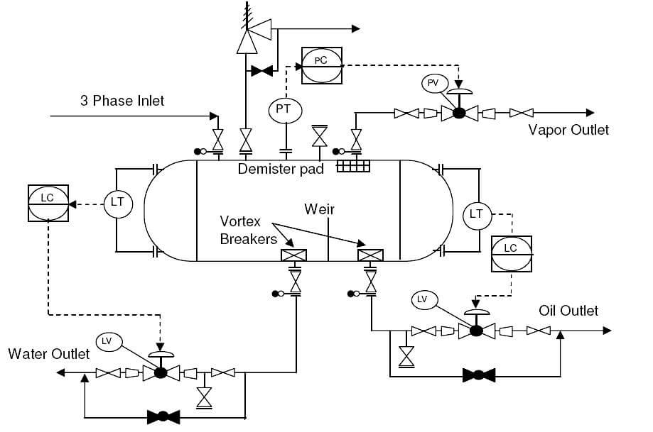
- Schematic Representation: P&IDs are schematic diagrams that show the relationships between piping, instrumentation, and system components. They use symbols and lines to represent pipes, equipment, and the flow of materials.
- Process Focus: These diagrams primarily focus on illustrating the functional relationships between the various systems and components in a process. They include detailed information on instrumentation, control devices, and operational details.
- Purpose: The main goal of a P&ID is to outline the process flow and control scheme in a facility. It serves as a critical tool in process design and is used throughout the lifecycle of a plant for understanding, operation, and maintenance.
- Includes Process Information: Unlike piping isometrics, P&IDs provide a wealth of process information, including pressure and temperature requirements, flow directions, and media used in the process.
Key Differences
- Dimensional Accuracy: Piping isometrics show the physical layout and dimensions of the piping system, while P&IDs focus on the process and functional aspects without maintaining scale or true dimensional relationships.
- Content: Piping isometrics are concerned with the detailed physical construction of the piping system. In contrast, P&IDs provide a comprehensive overview of the process flow, including instrumentation and control mechanisms.
- Use Case: Isometrics are primarily used by fabricators, pipefitters, and construction personnel for the physical creation and installation of the piping system. P&IDs are used by process engineers, operators, and maintenance personnel for understanding the process operation and for troubleshooting.
DIFFERENCE BETWEEN ORTHOGRAPHIC VS. ISOMETRICS
Orthographic and isometric drawings are both crucial in engineering and architecture, providing different perspectives and information about structures or objects. Understanding their differences is key to interpreting design plans correctly.
Orthographic Drawings

- Definition: Orthographic drawings are a series of two-dimensional (2D) views of an object or structure from different perspectives, usually including the top view, front view, and side view.
- Purpose: They are used to provide comprehensive details about the shape, size, and features of each part of an object or structure. Each view is a precise 2D representation, allowing for accurate measurements and a clear understanding of the dimensions.
- Accuracy and Scale: Orthographic drawings are typically drawn to scale, offering exact dimensions and allowing detailed measurements directly from the drawing.
- Use Cases: Widely used in mechanical and architectural design, allowing builders, fabricators, and engineers to see detailed views of components for manufacturing or construction.
Isometric Drawings
- Definition: Isometric drawings are a form of 3D representation in which the object or structure is shown on a single plane with all three axes (X, Y, and Z) displayed at 120 degrees to each other. This creates a pseudo-3D effect that offers a more visual representation of how the object or structure appears in reality.
- Purpose: The aim is to provide a visual representation of the object, showing its overall form and how different parts relate to each other in three dimensions.
- Accuracy and Scale: While isometric drawings offer a 3D view, they are not always drawn to scale in terms of measurements. Dimensions may be included, but the primary goal is visual representation rather than precise scaling.
- Use Cases: Useful for understanding the complex assembly of parts, and spatial relationships, and visualizing the finished product. Common in piping design, furniture design, and when a visual overview is more beneficial than detailed measurements.
Key Differences
- Dimensionality: Orthographic drawings are strictly 2D and provide details through multiple views, whereas isometric drawings offer a 3D representation on a 2D plane.
- Perspective: Orthographics break down the object into separate views, each from a perpendicular angle, while isometrics show the object from an angle that reveals multiple sides simultaneously.
- Detail vs. Overview: Orthographic drawings excel in providing detailed and accurate measurements of each part or aspect of a design. Isometric drawings, on the other hand, give a general overview, making it easier to understand the form and spatial relations.
- Scale: Orthographic drawings are usually to scale, offering exact dimensions, while isometric drawings might not be scaled, focusing on representation over precision.
ISOMETRIC, PLAN, AND ELEVATION VIEW OF PIPING SYSTEMS
Isometric, plan, and elevation presentations are three distinct types of drawings used to depict piping systems in engineering and construction. Each serves a unique purpose and offers different perspectives to engineers, designers, and builders, ensuring a comprehensive understanding of the piping system’s layout, design, and functionality.
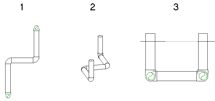
Here’s how each presentation contributes to the visualization and construction of a piping system:
Isometric Presentations
- Perspective: Isometric drawings provide a three-dimensional view on a two-dimensional plane, allowing for the visualization of the piping system in a pseudo-3D format. These drawings represent the system with all three axes (X, Y, and Z) drawn at 120 degrees to each other, offering a clearer picture of how components fit together.
- Usefulness: They are invaluable for understanding the spatial relationships between different parts of the piping system, including pipes, fittings, valves, and equipment. Isometric drawings are also crucial for fabrication, assembly, and identifying potential clashes before construction.
- Details: Isometric presentations include details such as pipe dimensions, material specifications, and annotations for welds, fittings, and supports.
Plan Presentations
- Perspective: Plan views are top-down projections that show the layout of the piping system as seen from above. This view flattens the system onto a single plane, highlighting the routing of pipes across a facility’s floor plan.
- Usefulness: Plan views are essential for understanding the horizontal relationship and routing of pipes. They help in planning the physical layout of the piping with other structural elements, machinery, and access pathways within a building or site.
- Details: These drawings detail the locations where pipes run, intersect, enter, or exit a building, and where they connect to equipment, showing the system’s layout of the overall site or building plan.
Elevation Presentations
- Perspective: Elevation drawings are side views (front, rear, or side) of the piping system, providing a vertical depiction of the pipes. These presentations offer insight into the height and vertical routing of the piping system.
- Usefulness: Elevations are critical for understanding how the piping system navigates changes in levels, including rises and drops, and how it is supported at various heights. They are particularly useful for visualizing the system in multi-storied buildings or complex installations.
- Details: Elevation views include height dimensions, and vertical runs, and indicate the placement of supports, valves, and special fittings. They also show the relationship between different system components at various elevations.
Integrating Isometric, Plan, and Elevation Drawings
Together, isometric, plan and elevation drawings provide a full picture of the piping system from all angles, ensuring that designers can address both the detailed specifics and the overall layout. The integration of these presentations allows for:
- Comprehensive planning and accurate installation.
- Efficient use of space and materials.
- Prevention of clashes with other systems.
- Clear communication among all stakeholders involved in the project, including engineers, fabricators, installers, and maintenance personnel.

Hatches in Isometric Drawings
In isometric drawings, hatching is a technique used to represent different materials, components, or areas with distinct visual patterns. Hatching helps convey information about the properties or construction of elements within the drawing.
Essentially, hatching patterns serve the essential function of visually conveying information about the materials, insulation, or contents within the pipes, without the need for extensive textual descriptions. These graphical textures or patterns are standardized within an organization or project but can vary across the industry.

Here’s a guide on how hatches are typically used in isometric drawings:
1. Types of Hatching Patterns
- Solid Fill: Represents solid or opaque materials. It is often used for structural elements or equipment.
- Crosshatch: Indicates a specific material or component. Different crosshatch patterns can be used to distinguish between materials like concrete, steel, or insulation.
- Dotted Hatching: Used to represent hidden or obscured parts. This can include elements that are not in the line of sight or are behind other components.
2. Representation of Materials
- Brick Walls: A crosshatch pattern may be used to represent brick walls. The pattern can vary based on the type of brick or masonry used.
- Concrete: Solid fills or a grid pattern may represent concrete structures.
- Insulation: A specific crosshatch pattern might be used to indicate the presence of insulation material around pipes or equipment.
3. Components and Equipment
- Pumps and Tanks: Different hatch patterns can be used for pumps, tanks, and other equipment to distinguish them from structural elements.
- Valves and Fittings: Hatching may be applied to highlight valves, fittings, and other small components.
4. Hidden Lines
Hidden or Internal Components: Dotted or dashed lines may be used to indicate components that are not visible from the current view or are hidden behind other elements.
5. Scale and Consistency
- Consistent Use: It’s essential to use hatching consistently throughout the drawing. Similar materials or components should have the same hatching pattern for clarity.
- Scale: The scale of the drawing may influence the density and size of hatching patterns. Ensure that the hatching remains readable and clear at the chosen scale.
6. Key or Legend
Key or Legend: A key or legend is often included in isometric drawings to explain the meaning of different hatching patterns. This helps ensure that everyone interpreting the drawing understands the conventions used.
7. Color vs. Black and White
Color Coding: In color isometric drawings, hatching patterns may be complemented with different colors to enhance clarity and visual representation.
8. Software Considerations
CAD Software: When creating isometric drawings using computer-aided design (CAD) software, the software may provide tools for applying hatching patterns. Familiarize yourself with the hatching options in the chosen CAD software.
9. Industry Standards
Compliance: Some industries or companies may have specific standards for hatching patterns. Ensure that your drawings adhere to any relevant industry or company-specific standards.
10. Review and Clarification
Consultation: If there is uncertainty about the meaning of a particular hatching pattern, consult with the project team or relevant experts for clarification.
By effectively using hatching patterns in isometric drawings, you can enhance the clarity and communicative power of the visual representation, making it easier for others to interpret and understand the different elements within the drawing.
TYPES OF ISOMETRIC VIEWS
Isometric views are employed across various fields like engineering, architecture, and video game design to represent three-dimensional objects in two dimensions. They offer a unique way to visualize complex designs or structures by providing a comprehensive overview that combines height, width, and depth in a single view. There are several types of isometric views, each serving different purposes:
1. True Isometric View
This is the most common type of isometric drawing, where all three axes (X, Y, and Z) are rotated equally at 120 degrees to each other, and the dimensions along each axis are scaled equally. True isometric views are widely used in engineering drawings to represent components and systems in a pseudo-3D format, facilitating clear understanding without perspective distortion.
2. Dimetric View (or Bi-Axial)
In dimetric projections, two of the three axes share the same degree of foreshortening, while the third axis has a different level of foreshortening. This creates a more visually accurate representation of the object, albeit with a slight compromise on the uniformity seen in true isometric views. Dimetric views are less common but can be useful for emphasizing certain dimensions or features of an object.
3. Trimetric View (or Tri-Axial)
Trimetric projections feature three axes, each with a different degree of foreshortening. This type of view offers the most accurate visual representation of the three-dimensional object on a two-dimensional plane but at the cost of more complex construction and less intuitive measurement interpretation. Trimetric views are used when it’s important to convey the most accurate shape and size relationships in all three dimensions.
4. Isometric Axonometric View
An umbrella term for views where the object is rotated along one or more of its axes relative to the plane of projection. True isometric, dimetric, and trimetric views all fall under this category. They are characterized by parallel lines in the object being represented as parallel in the drawing, maintaining scale without converging to a vanishing point.
5. Pseudo-Isometric View
These are often used in video games and pixel art, where the strict mathematical rotation and scaling rules of true isometric views are relaxed for aesthetic or practical reasons. Pseudo-isometric views mimic the appearance of isometric drawings but do not adhere to the precise angles and scale, offering more flexibility in visualization.
6. Oblique Isometric View (or Oblique Planes)
Not technically isometric, oblique drawings project three-dimensional objects onto a two-dimensional plane with one axis (usually depth) depicted at an angle (commonly 45 degrees), while the others are shown in true scale. This approach simplifies the representation of details and measurements but sacrifices the uniform appearance of true isometric views.
