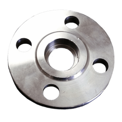

ASME SOCKET WELD FLANGE DIMENSIONS & WEIGHTS
The article shows the dimensions and weights of ASME/ANSI B16.5 socket-weld flanges (SW)
SOCKET WELD FLANGE SIZES IN INCHES
SOCKET WELD CLASS 150
Dimensions of socket weld flange class 150 (in inches)

| NPS | ID | OD | Bolt Circle (BC) | Raised Face (R) | Raised Face (RF) | H | D | ID 2* | Raised Face Thickness (T) | T1 | Flat Face Thickness (T2) | Bolt Hole (B) | No. of Bolt Holes |
|---|---|---|---|---|---|---|---|---|---|---|---|---|---|
| 1/2″ | 0.88″ | 3.50″ | 2.38″ | 1.38″ | .063″ | 1.19″ | .38″ | 0.62″ | .62″ | .38″ | .56″ | .62″ | 4 |
| 3/4″ | 1.09″ | 3.88″ | 2.75″ | 1.69″ | .063″ | 1.50″ | .44″ | 0.82″ | .62″ | .44″ | .56″ | .62″ | 4 |
| 1″ | 1.36″ | 4.25″ | 3.12″ | 2.00″ | .063″ | 1.94″ | .50″ | 1.05″ | .69″ | .50″ | .63″ | .62″ | 4 |
| 1-1/4″ | 1.70″ | 4.62″ | 3.50″ | 2.50″ | .063″ | 2.31″ | .56″ | 1.38″ | .81″ | .56″ | .75″ | .62″ | 4 |
| 1-1/2″ | 1.97″ | 5.00″ | 3.88″ | 2.88″ | .063″ | 2.56″ | .62″ | 1.61″ | .88″ | .62″ | .82″ | .62″ | 4 |
| 2″ | 2.44″ | 6.00″ | 4.75″ | 3.62″ | .063″ | 3.06″ | .69″ | 2.07″ | 1.00″ | .69″ | .94″ | .75″ | 4 |
| 2-1/2″ | 2.94″ | 7.00″ | 5.50″ | 4.12″ | .063″ | 3.56″ | .75″ | 2.47″ | 1.12″ | .82″ | 1.06″ | .75″ | 4 |
| 3″ | 3.57″ | 7.50″ | 6.00″ | 5.00″ | .063″ | 4.25″ | .81″ | 3.07″ | 1.19″ | .88″ | 1.13″ | .75″ | 4 |
| 3-1/2″ | 4.07″ | 8.50″ | 7.00″ | 5.50″ | .063″ | 4.81″ | .88″ | 3.55″ | 1.25″ | .88″ | 1.19″ | .75″ | 8 |
| 4″ | 4.57″ | 9.00″ | 7.50″ | 6.19″ | .063″ | 5.31″ | .94″ | 4.03″ | 1.31″ | .88″ | 1.25″ | .75″ | 8 |
| 5″ | 5.66″ | 10.00″ | 8.50″ | 7.31″ | .063″ | 6.44″ | .94″ | 5.05″ | 1.44″ | .88″ | 1.38″ | .88″ | 8 |
| 6″ | 6.72″ | 11.00″ | 9.50″ | 8.50″ | .063″ | 7.56″ | 1.06″ | 6.07″ | 1.56″ | .94″ | 1.50″ | .88″ | 8 |
| 8″ | 8.72″ | 13.50″ | 11.75″ | 10.62″ | .063″ | 9.69″ | 1.25″ | 7.98″ | 1.75″ | 1.06″ | 1.69″ | .88″ | 8 |
| 10″ | 10.88″ | 16.00″ | 14.25″ | 12.75″ | .063″ | 12.00″ | 1.31″ | 10.02″ | 1.94″ | 1.13″ | 1.88″ | 1.00″ | 12 |
| 12″ | 12.88″ | 19.00″ | 17.00″ | 15.00″ | .063″ | 14.38″ | 1.56″ | 12.00″ | 2.19″ | 1.19″ | 2.13″ | 1.00″ | 12 |
| 14″ | 14.14″ | 21.00″ | 18.75″ | 16.25″ | .063″ | 15.75″ | 1.63″ | 13.25″ | 2.25″ | 1.32″ | 2.19″ | 1.12″ | 12 |
| 16″ | 16.16″ | 23.50″ | 21.25″ | 18.50″ | .063″ | 18.00″ | 1.75″ | 15.25″ | 2.50″ | 1.38″ | 2.44″ | 1.12″ | 16 |
| 18″ | 18.18″ | 25.00″ | 22.75″ | 21.00″ | .063″ | 19.88″ | 1.94″ | 17.25″ | 2.69″ | 1.50″ | 2.63″ | 1.25″ | 16 |
| 20″ | 20.20″ | 27.50″ | 25.00″ | 23.00″ | .063″ | 22.00″ | 2.13″ | 19.25″ | 2.88″ | 1.63″ | 2.83″ | 1.25″ | 20 |
| 22″ | 22.22″ | 29.50″ | 27.25″ | 25.25″ | .063″ | 24.25″ | 2.38″ | 21.25″ | 3.13″ | 1.75″ | 3.07″ | 1.38″ | 20 |
| 24″ | 24.25″ | 32.00″ | 29.50″ | 27.25″ | .063″ | 26.12″ | 2.50″ | 23.25″ | 3.25″ | 1.82″ | 3.19″ | 1.38″ | 20 |
SOCKET WELD CLASS 300
Dimensions of socket weld flange class 300 (in inches)
| FLANGE NPS | Inside Diameter | Outside Diameter | Bolt Circle (BC) | Raised Face (R) | Raised Face (RF) | H | D | ID 2* | Raised Face Thickness (T) | T1 | Flat Face Thickness (T2) | Bolt Hole (B) | No. of Bolt Holes |
|---|---|---|---|---|---|---|---|---|---|---|---|---|---|
| 1/2″ | 0.88″ | 3.75″ | 2.62″ | 1.38″ | .063″ | 1.50″ | .38″ | 0.62″ | 0.88″ | 0.50″ | 0.82″ | 0.62″ | 4 |
| 3/4″ | 1.09″ | 4.62″ | 3.25″ | 1.69″ | .063″ | 1.88″ | .44″ | 0.82″ | 1.00″ | .056″ | 0.94″ | 0.75″ | 4 |
| 1″ | 1.36″ | 4.88″ | 3.50″ | 2.00″ | .063″ | 2.12″ | .50″ | 1.05″ | 1.06″ | 0.63″ | 1.00″ | 0.75″ | 4 |
| 1-1/4″ | 1.70″ | 5.25″ | 3.88″ | 2.50″ | .063″ | 2.50″ | .56″ | 1.38″ | 1.06″ | 0.69″ | 1.00″ | 0.75″ | 4 |
| 1-1/2″ | 1.97″ | 6.12″ | 4.50″ | 2.88″ | .063″ | 2.75″ | .62″ | 1.61″ | 1.19″ | 0.75″ | 1.13″ | 0.88″ | 4 |
| 2″ | 2.44″ | 6.50″ | 5.00″ | 3.62″ | .063″ | 3.31″ | .69″ | 2.07″ | 1.31″ | 0.82″ | 1.25″ | 0.75″ | 8 |
| 2-1/2″ | 2.94″ | 7.50″ | 5.88″ | 4.12″ | .063″ | 3.94″ | .75″ | 2.47″ | 1.50″ | 0.94″ | 1.44″ | 0.88″ | 8 |
| 3″ | 3.57″ | 8.25″ | 6.62″ | 5.00″ | .063″ | 4.62″ | .81″ | 3.07″ | 1.69″ | 1.06″ | 1.63″ | 0.88″ | 8 |
SOCKET WELD CLASS 600
Dimensions of socket weld flanges class 600 (in inches)
| FLANGE NPS | ID | OD | Bolt Circle (BC) | Raised Face (R) | Raised Face (RF) | H | D | ID 2* | Raised Face Thickness (T) | T1 | Flat Face Thickness (T2) | Bolt Hole (B) | No. of Bolt Holes |
|---|---|---|---|---|---|---|---|---|---|---|---|---|---|
| 1/2″ | 0.88″ | 3.75″ | 2.62″ | 1.38″ | .250″ | 1.50″ | .38″ | 0.55″ | 1.13″ | 0.56″ | 0.88″ | 0.62″ | 4 |
| 3/4″ | 1.09″ | 4.62″ | 3.25″ | 1.69″ | .250″ | 1.88″ | .44″ | 0.74″ | 1.25″ | 0.62″ | 1.00″ | 0.75″ | 4 |
| 1″ | 1.36″ | 4.88″ | 3.50″ | 2.00″ | .250″ | 2.12″ | .50″ | 0.96″ | 1.31″ | 0.69″ | 1.06″ | 0.75″ | 4 |
| 1-1/4″ | 1.70″ | 5.25″ | 3.88″ | 2.50″ | .250″ | 2.50″ | .56″ | 1.28″ | 1.37″ | 0.81″ | 1.12″ | 0.75″ | 4 |
| 1-1/2″ | 1.97″ | 6.12″ | 4.50″ | 2.88″ | .250″ | 2.75″ | .62″ | 1.50″ | 1.50″ | 0.88″ | 1.25″ | 0.88″ | 4 |
| 2″ | 2.44″ | 6.50″ | 5.00″ | 3.62″ | .250″ | 3.31″ | .69″ | 1.94″ | 1.69″ | 1.00″ | 1.44″ | 0.75″ | 8 |
| 2-1/2″ | 2.94″ | 7.50″ | 5.88″ | 4.12″ | .250″ | 3.94″ | .75″ | 2.32″ | 1.87″ | 1.12″ | 1.62″ | 0.88″ | 8 |
| 3″ | 3.57″ | 8.25″ | 6.62″ | 5.00″ | .250″ | 4.62″ | .81″ | 2.90″ | 2.06″ | 1.25″ | 1.81″ | 0.88″ | 8 |
SOCKET WELD CLASS 1500
Dimensions of socket weld flange class 1500 (in inches)
| FLANGE NPS | Inside Diameter | Outside Diameter | Bolt Circle (BC) | Raised Face (R) | Raised Face (RF) | H | D | ID 2* | Raised Face Thickness (T) | T1 | Flat Face Thickness (T2) | Bolt Hole (B) | No. of Bolt Holes |
|---|---|---|---|---|---|---|---|---|---|---|---|---|---|
| 1/2″ | 0.88″ | 4.75″ | 3.25″ | 1.38″ | .250″ | 1.50″ | .38″ | 0.55″ | 1.50″ | 0.88″ | 1.25″ | 0.88″ | 4 |
| 3/4″ | 1.09″ | 5.13″ | 3.50″ | 1.69″ | .250″ | 1.75″ | .44″ | 0.74″ | 1.63″ | 1.00″ | 1.38″ | 0.88″ | 4 |
| 1″ | 1.36″ | 5.88″ | 4.00″ | 2.00″ | .250″ | 2.06″ | .50″ | 0.96″ | 1.88″ | 1.13″ | 1.63″ | 1.00″ | 4 |
| 1-1/4″ | 1.70″ | 6.25″ | 4.38″ | 2.50″ | .250″ | 2.50″ | .56″ | 1.28″ | 1.88″ | 1.13″ | 1.63″ | 1.00″ | 4 |
| 1-1/2″ | 1.97″ | 7.00″ | 4.88″ | 2.88″ | .250″ | 2.75″ | .62″ | 1.50″ | 2.00″ | 1.25″ | 1.75″ | 1.13″ | 4 |
| 2″ | 2.44″ | 8.50″ | 6.50″ | 3.63″ | .250″ | 4.13″ | .69″ | 1.94″ | 2.50″ | 1.50″ | 2.25″ | 1.00″ | 8 |
| 2-1/2″ | 2.94″ | 9.63″ | 7.50″ | 4.13″ | .250″ | 4.88″ | .75″ | 2.32″ | 2.75″ | 1.63″ | 2.50″ | 1.13″ | 8 |
SOCKET WELD FLANGE SIZES IN MILLIMETERS
SOCKET WELD CLASS 150
Socket weld flange dimensions class 150 in millimeters (ASME B16.5)
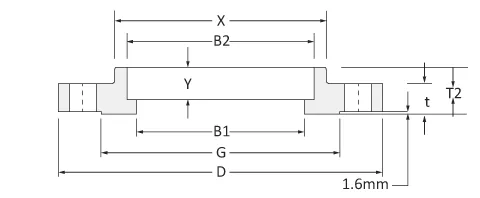
| Size inch | D mm | X mm | G mm | t mm | B1 mm | B2 mm | T2 mm | Y mm |
|---|---|---|---|---|---|---|---|---|
| 1/2 | 89 | 30.2 | 35.1 | 11.2 | 15.7 | 22.4 | 15.7 | 9.7 |
| 3/4 | 99 | 38.1 | 42.9 | 12.7 | 20.8 | 27.7 | 15.7 | 11.2 |
| 1 | 108 | 49.3 | 50.8 | 14.2 | 26.7 | 34.5 | 17.5 | 12.7 |
| 1¼ | 117 | 58.7 | 63.5 | 15.7 | 35.1 | 43.2 | 20.6 | 14.2 |
| 1½ | 127 | 65.0 | 73.2 | 17.5 | 40.9 | 49.5 | 22.4 | 15.7 |
| 2 | 152 | 77.7 | 91.9 | 19.1 | 52.6 | 62.0 | 25.4 | 17.5 |
| 2½ | 178 | 90.4 | 104.6 | 22.4 | 62.7 | 74.7 | 28.4 | 19.1 |
| 3 | 191 | 108.0 | 127.0 | 23.9 | 78.0 | 90.7 | 30.2 | 20.6 |
| 3½ | 216 | 122.2 | 139.7 | 23.9 | 90.2 | 103.4 | 31.8 | 22.4 |
| 4 | 229 | 134.9 | 157.2 | 23.9 | 102.4 | 116.1 | 33.3 | 23.9 |
| 5 | 254 | 163.6 | 185.7 | 23.9 | 128.3 | 143.8 | 36.6 | 23.9 |
| 6 | 279 | 192.0 | 215.9 | 25.4 | 154.2 | 170.7 | 39.6 | 26.9 |
| 8 | 343 | 246.1 | 269.7 | 28.4 | 202.7 | 221.5 | 44.5 | 31.8 |
| 10 | 406 | 304.8 | 323.9 | 30.2 | 254.5 | 276.4 | 49.3 | 33.3 |
| 12 | 483 | 365.3 | 381.0 | 31.8 | 304.8 | 327.2 | 55.6 | 39.6 |
| 14 | 533 | 400.1 | 412.8 | 35.1 | 336.6 | 359.2 | 57.2 | 41.4 |
| 16 | 597 | 457.2 | 469.9 | 36.6 | 387.4 | 410.5 | 63.5 | 44.5 |
| 18 | 635 | 505.0 | 533.4 | 39.6 | 438.2 | 461.8 | 68.3 | 49.3 |
| 20 | 699 | 558.8 | 584.2 | 42.9 | 489.0 | 513.1 | 73.2 | 54.1 |
| 24 | 813 | 663.4 | 692.2 | 47.8 | 590.6 | 616.0 | 82.6 | 63.5 |
| Size | Drilling | Bolting | |||||
|---|---|---|---|---|---|---|---|
| inch | Bolt circle Diameter mm | Holes # | Holes Dia. mm | Bolt Dia. inch. | Length FF Flange | Length RF Flange | Length RTJ Flange |
| 1/2 | 60.5 | 4 | 15.7 | 1/2 | 50.8 | 57.2 | – |
| 3/4 | 69.9 | 4 | 15.7 | 1/2 | 50.8 | 63.5 | – |
| 1 | 79.2 | 4 | 15.7 | 1/2 | 57.2 | 63.5 | 76.2 |
| 1¼ | 88.9 | 4 | 15.7 | 1/2 | 57.2 | 69.9 | 82.6 |
| 1½ | 98.6 | 4 | 15.7 | 1/2 | 63.5 | 69.9 | 82.6 |
| 2 | 120.7 | 4 | 19.1 | 5/8 | 69.9 | 82.6 | 95.3 |
| 2½ | 139.7 | 4 | 19.1 | 5/8 | 76.2 | 88.9 | 101.6 |
| 3 | 152.4 | 4 | 19.1 | 5/8 | 76.2 | 88.9 | 101.6 |
| 3½ | 177.8 | 8 | 19.1 | 5/8 | 76.2 | 88.9 | 101.6 |
| 4 | 190.5 | 8 | 19.1 | 5/8 | 76.2 | 88.9 | 101.6 |
| 5 | 215.9 | 8 | 22.4 | 3/4 | 82.6 | 95.3 | 108.0 |
| 6 | 241.3 | 8 | 22.4 | 3/4 | 82.6 | 101.6 | 114.3 |
| 8 | 298.5 | 8 | 22.4 | 3/4 | 88.9 | 108.0 | 120.7 |
| 10 | 362.0 | 12 | 25.4 | 7/8 | 101.6 | 114.3 | 127.0 |
| 12 | 431.8 | 12 | 25.4 | 7/8 | 101.6 | 120.7 | 133.4 |
| 14 | 476.3 | 12 | 28.4 | 1 | 114.3 | 133.4 | 146.1 |
| 16 | 539.8 | 16 | 28.4 | 1 | 114.3 | 133.4 | 146.1 |
| 18 | 577.9 | 16 | 31.8 | 11/8 | 127.0 | 146.1 | 158.8 |
| 20 | 635.0 | 20 | 31.8 | 11/8 | 139.7 | 158.8 | 171.5 |
| 24 | 749.3 | 20 | 35.1 | 1¼ | 152.4 | 171.5 | 184.2 |
SOCKET WELD CLASS 300
Socket weld flange dimensions class 300 in millimeters (ASME B16.5)
| Size inch | D mm | X mm | G mm | t mm | B1 mm | B2 mm | T2 mm | Y mm |
|---|---|---|---|---|---|---|---|---|
| 1/2 | 95 | 38.1 | 35.1 | 14.2 | 15.7 | 22.4 | 22.4 | 9.7 |
| 3/4 | 117 | 47.8 | 42.9 | 15.7 | 20.8 | 27.7 | 25.4 | 11.2 |
| 1 | 124 | 53.8 | 50.8 | 17.5 | 26.7 | 34.5 | 26.9 | 12.7 |
| 1¼ | 133 | 63.5 | 63.5 | 19.1 | 35.1 | 43.2 | 26.9 | 14.2 |
| 1½ | 155 | 69.9 | 73.2 | 20.6 | 40.9 | 49.5 | 30.2 | 15.7 |
| 2 | 165 | 84.1 | 91.9 | 22.4 | 52.6 | 62.0 | 33.3 | 17.5 |
| 2½ | 191 | 100.1 | 104.6 | 25.4 | 62.7 | 74.7 | 38.1 | 19.1 |
| 3 | 210 | 117.3 | 127.0 | 28.4 | 78.0 | 90.7 | 42.9 | 20.6 |
| 3½ | 229 | 133.4 | 139.7 | 30.2 | 90.2 | 103.4 | 44.5 | 22.4 |
| 4 | 254 | 146.1 | 157.2 | 31.8 | 102.4 | 116.1 | 47.8 | 23.9 |
| 5 | 279 | 177.8 | 185.7 | 35.1 | 128.3 | 143.8 | 50.8 | 23.9 |
| 6 | 318 | 206.2 | 215.9 | 36.6 | 154.2 | 170.7 | 52.3 | 26.9 |
| 8 | 381 | 260.4 | 269.7 | 41.1 | 202.7 | 221.5 | 62.0 | 31.8 |
| 10 | 445 | 320.5 | 323.9 | 47.8 | 254.5 | 276.4 | 66.5 | 33.3 |
| 12 | 521 | 374.7 | 381.0 | 50.8 | 304.8 | 327.2 | 73.2 | 39.6 |
| 14 | 584 | 425.5 | 412.8 | 63.8 | 336.6 | 359.2 | 76.2 | 41.4 |
| 16 | 648 | 482.6 | 469.9 | 57.2 | 387.4 | 410.5 | 82.6 | 44.5 |
| 18 | 711 | 533.4 | 533.4 | 60.5 | 438.2 | 461.8 | 88.9 | 49.3 |
| 20 | 775 | 587.2 | 584.2 | 63.5 | 489.0 | 513.1 | 95.3 | 54.1 |
| 24 | 914 | 701.5 | 692.2 | 69.9 | 590.6 | 616.0 | 106.4 | 63.5 |
| Size | Drilling | Bolting | |||||
|---|---|---|---|---|---|---|---|
| inch | Bolt circle Diameter mm | Holes # | Holes Dia. mm | Bolt Dia. inch. | Length FF Flange | Length RF Flange | Length RTJ Flange |
| 1/2 | 66.5 | 4 | 15.7 | 1/2 | 57.2 | 63.5 | 76.2 |
| 3/4 | 82.6 | 4 | 19.1 | 5/8 | 63.5 | 76.2 | 88.9 |
| 1 | 88.9 | 4 | 19.1 | 5/8 | 63.5 | 76.2 | 88.9 |
| 1¼ | 98.6 | 4 | 19.1 | 5/8 | 69.9 | 82.6 | 95.3 |
| 1½ | 114.3 | 4 | 22.4 | 3/4 | 76.2 | 88.9 | 101.6 |
| 2 | 127.0 | 8 | 19.1 | 5/8 | 76.2 | 88.9 | 101.6 |
| 2½ | 149.4 | 8 | 22.4 | 3/4 | 82.6 | 101.6 | 114.3 |
| 3 | 168.1 | 8 | 22.4 | 3/4 | 88.9 | 108.0 | 120.7 |
| 3½ | 184.2 | 8 | 22.4 | 3/4 | 95.3 | 108.0 | 127.0 |
| 4 | 200.2 | 8 | 22.4 | 3/4 | 95.3 | 114.3 | 127.0 |
| 5 | 235.0 | 8 | 22.4 | 3/4 | 108.0 | 120.7 | 133.4 |
| 6 | 269.7 | 12 | 22.4 | 3/4 | 108.0 | 120.7 | 139.7 |
| 8 | 330.2 | 12 | 25.4 | 7/8 | 120.7 | 139.7 | 152.4 |
| 10 | 387.4 | 16 | 28.4 | 1 | 139.7 | 158.8 | 171.5 |
| 12 | 450.9 | 16 | 31.8 | 11/8 | 146.1 | 171.5 | 184.2 |
| 14 | 514.4 | 20 | 31.8 | 11/8 | 158.8 | 177.8 | 190.5 |
| 16 | 571.5 | 20 | 35.1 | 1¼ | 165.1 | 190.5 | 203.2 |
| 18 | 628.7 | 24 | 35.1 | 1¼ | 171.5 | 196.9 | 209.6 |
| 20 | 685.8 | 24 | 35.1 | 1¼ | 184.2 | 203.2 | 222.3 |
| 24 | 812.8 | 24 | 41.1 | 1½ | 203.2 | 228.6 | 254.0 |
SOCKET WELD CLASS 600
Socket weld flange dimensions class 600 in millimeters (ASME B16.5)
| Size inch | D mm | X mm | G mm | t mm | B1 mm | B2 mm | T2 mm | Y mm |
|---|---|---|---|---|---|---|---|---|
| 1/2 | 95 | 38.1 | 35.1 | 14.2 | B36.10/.19 | 22.4 | 22.4 | 9.7 |
| 3/4 | 117 | 47.8 | 42.9 | 15.7 | B36.10/.19 | 27.7 | 25.4 | 11.2 |
| 1 | 124 | 53.8 | 50.8 | 17.5 | B36.10/.19 | 34.5 | 26.9 | 12.7 |
| 1¼ | 133 | 63.5 | 63.5 | 20.6 | B36.10/.19 | 43.2 | 28.4 | 14.2 |
| 1½ | 155 | 69.9 | 73.2 | 22.4 | B36.10/.19 | 49.5 | 31.8 | 15.7 |
| 2 | 165 | 84.1 | 91.9 | 25.4 | B36.10/.19 | 62.0 | 36.6 | 17.5 |
| 2½ | 191 | 100.1 | 104.6 | 28.4 | B36.10/.19 | 74.7 | 41.1 | 19.1 |
| 3 | 210 | 117.3 | 127.0 | 31.8 | B36.10/.19 | 90.7 | 46.0 | 20.6 |
| 3½ | 229 | 133.4 | 139.7 | 35.1 | B36.10/.19 | 103.4 | 49.3 | 22.4 |
| 4 | 273 | 152.4 | 157.2 | 38.1 | B36.10/.19 | 116.1 | 53.8 | 23.9 |
| 5 | 330 | 189.0 | 185.7 | 44.5 | B36.10/.19 | 143.8 | 60.5 | 23.9 |
| 6 | 356 | 222.3 | 215.9 | 47.8 | B36.10/.19 | 170.7 | 66.5 | 26.9 |
| 8 | 419 | 273.1 | 269.7 | 55.6 | B36.10/.19 | 221.5 | 76.2 | 31.8 |
| 10 | 508 | 342.9 | 323.9 | 63.5 | B36.10/.19 | 276.4 | 85.9 | 33.3 |
| 12 | 559 | 400.1 | 381.0 | 66.5 | B36.10/.19 | 327.2 | 91.9 | 39.6 |
| 14 | 603 | 431.8 | 412.8 | 69.9 | B36.10/.19 | 359.2 | 93.7 | 41.4 |
| 16 | 686 | 495.3 | 469.9 | 76.2 | B36.10/.19 | 410.5 | 106.4 | 44.5 |
| 18 | 743 | 546.1 | 533.4 | 82.6 | B36.10/.19 | 461.8 | 117.3 | 49.3 |
| 20 | 813 | 609.6 | 584.2 | 88.9 | B36.10/.19 | 513.1 | 127.0 | 54.1 |
| 24 | 940 | 717.6 | 692.2 | 101.6 | B36.10/.19 | 616.0 | 139.7 | 63.5 |
| Size | Drilling | Bolting | |||||
|---|---|---|---|---|---|---|---|
| inch | Bolt circle Diameter mm | Holes # | Holes Dia. mm | Bolt Dia. inch. | Length FF Flange | Length RF Flange | Length RTJ Flange |
| 1/2 | 66.5 | 4 | 15.7 | 1/2 | 76.2 | 69.9 | 76.2 |
| 3/4 | 82.6 | 4 | 19.1 | 5/8 | 88.9 | 82.6 | 88.9 |
| 1 | 88.9 | 4 | 19.1 | 5/8 | 88.9 | 82.6 | 88.9 |
| 1¼ | 98.6 | 4 | 19.1 | 5/8 | 95.3 | 88.9 | 95.3 |
| 1½ | 114.3 | 4 | 22.4 | 3/4 | 108.0 | 101.6 | 108.0 |
| 2 | 127.0 | 8 | 19.1 | 5/8 | 108.0 | 101.6 | 108.0 |
| 2½ | 149.4 | 8 | 22.4 | 3/4 | 120.7 | 114.3 | 120.7 |
| 3 | 168.1 | 8 | 22.4 | 3/4 | 127.0 | 120.7 | 127.0 |
| 3½ | 184.2 | 8 | 25.4 | 7/8 | 139.7 | 133.4 | 139.7 |
| 4 | 215.9 | 8 | 25.4 | 7/8 | 146.1 | 139.7 | 146.1 |
| 5 | 266.7 | 8 | 28.4 | 1 | 165.1 | 158.8 | 165.1 |
| 6 | 292.1 | 12 | 28.4 | 1 | 171.5 | 165.1 | 171.5 |
| 8 | 349.3 | 12 | 31.8 | 11/8 | 190.5 | 184.2 | 196.9 |
| 10 | 431.8 | 16 | 35.1 | 1¼ | 215.9 | 209.6 | 215.9 |
| 12 | 489.0 | 20 | 35.1 | 1¼ | 222.3 | 215.9 | 222.3 |
| 14 | 527.1 | 20 | 38.1 | 13/8 | 235.0 | 228.6 | 235.0 |
| 16 | 603.3 | 20 | 41.1 | 1½ | 254.0 | 247.7 | 254.0 |
| 18 | 654.1 | 20 | 44.5 | 15/8 | 273.1 | 266.7 | 273.1 |
| 20 | 723.9 | 24 | 44.5 | 15/8 | 285.8 | 279.4 | 292.1 |
| 24 | 838.2 | 24 | 50.8 | 17/8 | 330.2 | 323.9 | 336.6 |
TOLERANCE OF SOCKET WELD FLANGES
ASME B16.5 provides specific tolerances for socket-weld flanges, which are designed for small-size high-pressure piping. These tolerances ensure proper fit, alignment, and sealing capability within the piping systems. Socket-weld flanges have a recessed area where the pipe is inserted before being welded around the outer diameter. Below is a summary of general tolerance values for key dimensions of socket-weld flanges according to ASME B16.5. For precise values, especially for specific sizes and classes, consulting the ASME B16.5 standard is essential.
Diameter of Bolt Circle (P):
Tolerance: ±1.6 mm (±1/16 inch) for flanges up to and including NPS 24. This ensures even distribution of bolt loads and proper alignment.
Diameter of Bolt Holes (Q):
Tolerance: Typically, bolt holes are oversized relative to the bolt diameter by +3 mm (1/8 inch) to facilitate alignment and assembly.
Flange Thickness (T):
Tolerance: Can vary but a general guideline for flanges up to NPS 24 is ±3 mm (±1/8 inch). This tolerance accounts for the necessary strength and pressure containment without adding unnecessary weight.
Outside Diameter of Flange (O):
Tolerance: ±1.6 mm (±1/16 inch) for sizes up to NPS 24, ensuring compatibility with mating components and equipment.
Socket Depth (D):
Tolerance: The depth of the socket is crucial for ensuring that the pipe fits properly before welding. Tolerances ensure that there is enough room for the pipe to be inserted to the correct depth, facilitating a proper weld.
Bore Diameter (B):
Tolerance: The tolerance on the bore diameter ensures the flange will not impede fluid flow or cause excessive turbulence. The tolerance typically allows for a slight clearance over the outside diameter of the pipe, ensuring a fit that facilitates welding without excessive gap or interference.
Counterbore Diameter (G) and Depth:
Tolerance: Specific tolerances apply to the counterbore’s diameter and depth, ensuring the pipe sits properly within the flange socket for a secure weld.
Facing Finish:
Tolerance: The surface finish of the flange face is specified in terms of Ra (Roughness Average) to ensure compatibility with the gasket material and a proper seal. Tolerances are provided based on the type of facing and gasket used.
Adherence to these tolerances is critical for the functionality and integrity of the socket-weld flange connections. The correct implementation ensures proper alignment, weld quality, and sealing performance, contributing to the safety and reliability of the overall piping system. For detailed and specific tolerance values, it’s crucial to refer to the latest edition of ASME B16.5.
SW FLANGE WEIGHTS
SW FLANGE WEIGHT in KGS.
The table shows the ASME B16.5 socket-weld (SW) flange weights in Kgs. by Flange NPS and Class (carbon/alloy steel materials; for higher grades, consider adjusting weight using the delta-specific weight carbon/other grades)
| NPS | Class 150 | Class 300 | Class 400 | Class 600 | Class 900 | Class 1500 |
| 1/2 | 0.9 | 1.4 | 0.9 | 0.9 | 2.7 | 2.7 |
| 3/4 | 0.9 | 1.4 | 1.4 | 1.4 | 2.7 | 2.7 |
| 1 | 0.9 | 1.4 | 1.6 | 1.8 | 3.4 | 3.6 |
| 1¼ | 1.4 | 1.8 | 2 | 2.3 | 4.5 | 4.5 |
| 1½ | 1.4 | 2.7 | 2.9 | 3.2 | 6.3 | 6.3 |
| 2 | 2.3 | 3.2 | 3.6 | 4.1 | 9.9 | 11.3 |
| 2½ | 3.6 | 4.5 | 5.4 | 5.9 | 13.9 | 16.2 |
| 3 | 4.1 | 5.9 | 6.8 | 7.2 | 16.2 | 21.6 |
| 3½ | 4 | 7.7 | 9.5 | 9.5 | ||
| 4 | 5.9 | 9.9 | 11.7 | 16.7 | 23.9 | 32.9 |
| 5 | 6.8 | 12.6 | 13.9 | 28.4 | 37.4 | 59.4 |
| 6 | 8.6 | 17.6 | 19.8 | 36 | 49.5 | 74.3 |
| 8 | 13.5 | 26.1 | 30.2 | 51.8 | 77.4 | 117 |
| 10 | 19.4 | 36.5 | 40 | 79.7 | 110.3 | 196.2 |
| 12 | 28.8 | 51.8 | 58.5 | 96.8 | 146.7 | 300.2 |
| 14 | 40.5 | 74.3 | 85 | 116.6 | 180 | 423 |
| 16 | 44.1 | 85.5 | 113.9 | 164.7 | 206.6 | 562.5 |
| 18 | 58.5 | 112.5 | 139.5 | 214.2 | 291.2 | 731.3 |
| 20 | 74.3 | 141.8 | 170.1 | 275.4 | 356.4 | 922.5 |
| 22 | 83.3 | 166.5 | 182.3 | 265.5 | ||
| 24 | 99 | 213.8 | 242.6 | 394.2 | 666 | 1271 |
SW FLANGE WEIGHT in LBS.
The table shows the ASME B16.5 socket-weld (SW) flange weights in Lbs. by Flange NPS and Class (carbon/alloy steel materials; for higher grades, consider adjusting weight using the delta-specific weight carbon/other grades)
| CLASS 150 | Nominal Pipe Size | Socket Weld Weight in Lbs./unit |
| ½ | 2 | |
| ¾ | 2 | |
| 1 | 2 | |
| 1¼ | 3 | |
| 1½ | 3 | |
| 2 | 5 | |
| 2½ | 8 | |
| 3 | 9 | |
| 3½ | 11 | |
| 4 | 13 | |
| 5 | 15 | |
| 6 | 19 | |
| 8 | 30 | |
| 10 | 43 | |
| 12 | 64 | |
| 14 | 90 | |
| 16 | 98 | |
| 18 | 130 | |
| 20 | 165 | |
| 22 | 185 | |
| 24 | 220 | |
| CLASS 300 | Nominal Pipe Size | Socket Weld Weight in Lbs./unit |
| ½ | 3 | |
| ¾ | 3 | |
| 1 | 3 | |
| 1¼ | 4 | |
| 1½ | 6 | |
| 2 | 7 | |
| 2½ | 10 | |
| 3 | 13 | |
| 3½ | 17 | |
| 4 | 22 | |
| 5 | 28 | |
| 6 | 39 | |
| 8 | 58 | |
| 10 | 81 | |
| 12 | 115 | |
| 14 | 165 | |
| 16 | 190 | |
| 18 | 250 | |
| 20 | 315 | |
| 22 | 370 | |
| 24 | 475 | |
| CLASS 400 | Nominal Pipe Size | Socket Weld Weight in Lbs./unit |
| ½ | 2 | |
| ¾ | 3 | |
| 1 | 3.5 | |
| 1¼ | 4.5 | |
| 1½ | 6.5 | |
| 2 | 8 | |
| 2½ | 12 | |
| 3 | 15 | |
| 3½ | 21 | |
| 4 | 26 | |
| 5 | 31 | |
| 6 | 44 | |
| 8 | 67 | |
| 10 | 91 | |
| 12 | 130 | |
| 14 | 191 | |
| 16 | 253 | |
| 18 | 310 | |
| 20 | 378 | |
| 22 | 405 | |
| 24 | 539 | |
| CLASS 600 | Nominal Pipe Size | Socket Weld Weight in Lbs./unit |
| ½ | 2 | |
| ¾ | 3 | |
| 1 | 4 | |
| 1¼ | 5 | |
| 1½ | 7 | |
| 2 | 9 | |
| 2½ | 13 | |
| 3 | 16 | |
| 3½ | 21 | |
| 4 | 37 | |
| 5 | 63 | |
| 6 | 80 | |
| 8 | 115 | |
| 10 | 177 | |
| 12 | 215 | |
| 14 | 259 | |
| 16 | 366 | |
| 18 | 476 | |
| 20 | 612 | |
| 22 | 590 | |
| 24 | 876 | |
| CLASS 900 | Nominal Pipe Size | Socket Weld Weight in Lbs./unit |
| ½ | 6 | |
| ¾ | 6 | |
| 1 | 7.5 | |
| 1¼ | 10 | |
| 1½ | 14 | |
| 2 | 22 | |
| 2½ | 31 | |
| 3 | 36 | |
| 4 | 53 | |
| 5 | 83 | |
| 6 | 110 | |
| 8 | 172 | |
| 10 | 245 | |
| 12 | 326 | |
| 14 | 400 | |
| 16 | 459 | |
| 18 | 647 | |
| 20 | 792 | |
| 24 | 1480 | |
| CLASS 1500 | Nominal Pipe Size | Socket Weld Weight in Lbs./unit |
| ½ | 6 | |
| ¾ | 6 | |
| 1 | 8 | |
| 1¼ | 10 | |
| 1½ | 14 | |
| 2 | 25 | |
| 2½ | 36 | |
| 3 | 48 | |
| 4 | 73 | |
| 5 | 132 | |
| 6 | 165 | |
| 8 | 260 | |
| 10 | 436 | |
| 12 | 667 | |
| 14 | 940 | |
| 16 | 1250 | |
| 18 | 1625 | |
| 20 | 2050 | |
| 24 | 2825 |


One Response
Need dimension for DN1200,DN950,DN800 Cl.150 for socket weld flanges.