
SPECTACLE BLIND
WHAT IS A SPECTACLE BLIND (“FIGURE-8”)
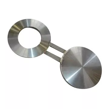
A spectacle blind, also known as a figure-8 blind, is a safety device used in piping systems to isolate a section of the pipe for maintenance, inspection, or shutdown.
It consists of two metal discs connected by a small section in the middle, resembling a pair of spectacles or the figure-8, hence its name. One disc is a solid plate (blind), and the other is a ring (spacer). The spectacle blind is inserted between two flange joints to either block the flow completely (using the blind side) or allow it to pass through (using the spacer side).

The reference specification for pipeline isolation devices (including spectacle blinds, ring spacers, and line blanks) is ASME B16.48.
Functionality and Use:
- Isolation: When the solid plate (blind) side faces the pipeline, it acts as a barrier, preventing flow and ensuring that the section is completely isolated. This is crucial for maintenance work or in emergency shutdown situations where it’s necessary to ensure no fluid passes through a segment of the piping system.
- Operational Flow: When the system is in normal operation, the ring (spacer) side is positioned to align with the pipe, allowing unrestricted flow. The spacer essentially acts as part of the pipeline during normal operations.
- Quick Changeover: The design of the spectacle blind enables quick and easy changeover between the open (spacer) and closed (blind) positions by simply rotating the spectacle blind without removing it from the flange. This convenience makes it highly efficient for systems that require frequent switching between operation and maintenance modes.
Advantages:
- Versatility: Spectacle blinds are suitable for various industrial applications, including oil and gas, chemical processing, and power generation, where pipeline isolation is frequently necessary.
- Safety: By providing a physical barrier in the pipeline, spectacle blinds significantly enhance safety during maintenance or in case of system failure.
- Cost-Effectiveness: Since they can be easily rotated without being fully removed from the pipeline, spectacle blinds reduce downtime and labor costs associated with system isolation.
Considerations:
- Material Compatibility: Spectacle blinds are available in various materials to match the pipeline and flange materials, ensuring chemical compatibility and pressure integrity.
- Size and Pressure Rating: They must be sized correctly for the pipeline and rated for the operating pressure and temperature conditions of the system.
- Installation: Proper alignment and installation are crucial to ensure the effectiveness of the seal when the blind side is in use.
Spectacle blinds, spades, and ring spacers are installed between flanges to sections of a pipeline permanently or temporarily as shown in this YouTube video:
Spectacle blinds are available in standard sizes up to 24 inches and in forged material grades like ASTM A105 (carbon steel for high-temperature service), A350 (carbon steel for low-temperature service), and various ASTM A182 grades (alloy, stainless steel, duplex / super duplex). All these materials for forged pipeline products (chemical composition, and mechanical properties) are thoroughly reviewed in this article.
SPECTACLE BLIND MANUFACTURING & USE
Spectacle blinds are generally purchased from manufacturers of flanges but can be produced by steelworking centers as well.
Spectacle blinds (also defined as “spectacle flanges”) are produced starting from steel plates and are basically made of two interconnected discs: one is actually a ring (i.e. a disc with a hole of the same bore size as the pipeline), and the other is a solid disc. Carbon steel spectacle blinds are manufactured out of a single piece of steel, whereas alloy / stainless steel blinds are generally manufactured by welding more than 1 piece together (commonly 2, but up to three).
It is easy to understand if a spectacle blind is in an open or closed position, as one of the two discs is always outside the pipe (so when the ring is visible, the pipeline is closed; when the solid disc is visible outside, the pipeline is open). For spades and ring spacers, holes on the hangers inform the staff about the position.

SPECTACLE BLIND TYPES
There are three types of spectacle blinds:
- Flat face spectacle blind (FF): similar to a flat face flange, the surface of the disc is flat (suited for flat face gaskets, for low-pressure applications).
- Raised face spectacle blind (RF): likewise raised face flanges, there is an additional thickness on the surface of the disc. This type fits semi-metallic gaskets, as the spiral wound type.
- Ring joint face spectacle blind (RTJ): a groove is inscribed on the surface of the disc. This type is used in conjunction with ring joint gaskets.

SPECTACLE BLIND DIMENSIONS in MM ASME B16.48

CLASS 150
Class 150 Spectacle blind dimensions in mm
| Spectacle Blind NPS Dimensions Class 150 | A | B | C | t | W |
| 1/2 | 45 | 16 | 60 | 3 | 38 |
| 3/4 | 54 | 21 | 70 | 3 | 38 |
| 1 | 64 | 27 | 80 | 3 | 38 |
| 1¼ | 73 | 42 | 90 | 6.4 | 38 |
| 1½ | 83 | 48 | 100 | 6.4 | 38 |
| 2 | 102 | 61 | 120 | 6.4 | 51 |
| 2½ | 107 | 73 | 140 | 6.4 | 51 |
| 3 | 133 | 89 | 150 | 6.4 | 64 |
| 3½ | 159 | 102 | 175 | 9.7 | 64 |
| 4 | 172 | 114 | 190 | 9.7 | 64 |
| 5 | 194 | 141 | 215 | 9.7 | 76 |
| 6 | 219 | 168 | 240 | 12.7 | 76 |
| 8 | 276 | 219 | 300 | 12.7 | 76 |
| 10 | 337 | 273 | 360 | 15.7 | 102 |
| 12 | 406 | 324 | 430 | 19.1 | 102 |
| 14 | 448 | 356 | 475 | 19.1 | 108 |
| 16 | 511 | 406 | 460 | 22.4 | 108 |
| 18 | 546 | 457 | 580 | 25.4 | 114 |
| 20 | 603 | 508 | 635 | 28.4 | 121 |
| 24 | 714 | 610 | 750 | 31.8 | 140 |
CLASS 300
Class 300 Spectacle blind dimensions in mm
| Spectacle Blind NPS Dimensions Class 300 | A | B | C | t | W |
| 1/2 | 51 | 16 | 65 | 6.4 | 38 |
| 3/4 | 64 | 21 | 80 | 6.4 | 38 |
| 1 | 70 | 27 | 90 | 6.4 | 38 |
| 1¼ | 79 | 42 | 100 | 6.4 | 38 |
| 1½ | 92 | 48 | 115 | 6.4 | 38 |
| 2 | 108 | 61 | 125 | 9.7 | 51 |
| 2½ | 127 | 73 | 150 | 9.7 | 51 |
| 3 | 146 | 89 | 170 | 9.7 | 64 |
| 3½ | 162 | 102 | 185 | 12.7 | 64 |
| 4 | 178 | 114 | 200 | 12.7 | 64 |
| 5 | 213 | 141 | 235 | 15.7 | 76 |
| 6 | 248 | 168 | 270 | 15.7 | 76 |
| 8 | 305 | 219 | 330 | 22.4 | 76 |
| 10 | 359 | 273 | 385 | 25.4 | 102 |
| 12 | 419 | 324 | 450 | 28.4 | 102 |
| 14 | 483 | 356 | 515 | 31.8 | 108 |
| 16 | 536 | 406 | 570 | 38.1 | 108 |
| 18 | 594 | 457 | 630 | 41.1 | 114 |
| 20 | 651 | 508 | 685 | 44.5 | 121 |
| 24 | 772 | 610 | 810 | 50.8 | 140 |
CLASS 600
Class 300 Spectacle blind dimensions in mm
| Spectacle Blind NPS Dimensions Class 600 | A | B | C | t | W |
| 1/2 | 51 | 16 | 65 | 6.4 | 38 |
| 3/4 | 64 | 21 | 80 | 6.4 | 38 |
| 1 | 70 | 27 | 90 | 6.4 | 57 |
| 1¼ | 79 | 37 | 100 | 9.7 | 57 |
| 1½ | 92 | 43 | 115 | 9.7 | 67 |
| 2 | 108 | 55 | 125 | 9.7 | 57 |
| 2½ | 127 | 67 | 150 | 12.7 | 67 |
| 3 | 146 | 83 | 170 | 12.7 | 67 |
| 3½ | 159 | 96 | 185 | 15.7 | 76 |
| 4 | 191 | 108 | 215 | 15.7 | 76 |
| 5 | 238 | 135 | 265 | 19.1 | 86 |
| 6 | 264 | 162 | 290 | 22.4 | 86 |
| 8 | 318 | 212 | 350 | 28.4 | 95 |
| 10 | 397 | 265 | 430 | 35.1 | 105 |
| 12 | 454 | 315 | 490 | 41.1 | 105 |
| 14 | 489 | 346 | 525 | 44.5 | 114 |
| 16 | 562 | 397 | 605 | 50.8 | 124 |
| 18 | 610 | 448 | 655 | 53.8 | 133 |
| 20 | 679 | 497 | 725 | 63.5 | 133 |
| 24 | 787 | 597 | 840 | 73.2 | 152 |
CLASS 900
Class 900 Spectacle blind dimensions in mm
| Spectacle Blind NPS Dimensions Class 900 | A | B | C | t | W |
| 1/2 | 60 | 16 | 80 | 6.4 | 38 |
| 3/4 | 67 | 21 | 90 | 6.4 | 41 |
| 1 | 76 | 27 | 100 | 6.4 | 57 |
| 1¼ | 86 | 37 | 110 | 9.7 | 57 |
| 1½ | 95 | 43 | 125 | 9.7 | 67 |
| 2 | 140 | 55 | 165 | 12.7 | 57 |
| 2½ | 162 | 67 | 190 | 12.7 | 67 |
| 3 | 165 | 83 | 190 | 15.7 | 67 |
| 4 | 203 | 108 | 235 | 19.1 | 76 |
| 5 | 244 | 135 | 280 | 22.4 | 86 |
| 6 | 286 | 162 | 320 | 25.4 | 86 |
| 8 | 356 | 212 | 395 | 35.1 | 95 |
| 10 | 432 | 265 | 470 | 41.1 | 105 |
| 12 | 495 | 315 | 535 | 47.8 | 105 |
| 14 | 518 | 346 | 560 | 53.8 | 114 |
| 16 | 572 | 397 | 615 | 60.5 | 124 |
| 18 | 635 | 448 | 685 | 66.5 | 133 |
| 20 | 696 | 497 | 750 | 73.2 | 133 |
| 24 | 835 | 597 | 900 | 88.9 | 152 |
CLASS 1500
Class 1500 Spectacle blind dimensions in mm
| Spectacle Blind NPS Dimensions Class 1500 | A | B | C | t | W |
| 1/2 | 61 | 16 | 80 | 6.4 | 38 |
| 3/4 | 67 | 21 | 90 | 9.7 | 41 |
| 1 | 76 | 27 | 100 | 9.7 | 64 |
| 1¼ | 86 | 35 | 110 | 9.7 | 64 |
| 1½ | 95 | 41 | 125 | 12.7 | 70 |
| 2 | 140 | 53 | 165 | 12.7 | 70 |
| 2½ | 162 | 63 | 190 | 15.7 | 76 |
| 3 | 172 | 78 | 205 | 19.1 | 76 |
| 4 | 206 | 102 | 240 | 22.4 | 89 |
| 5 | 251 | 128 | 290 | 28.4 | 89 |
| 6 | 279 | 154 | 320 | 35.1 | 89 |
| 8 | 349 | 203 | 395 | 41.1 | 102 |
| 10 | 432 | 255 | 480 | 50.8 | 114 |
| 12 | 518 | 303 | 570 | 60.5 | 114 |
| 14 | 575 | 333 | 635 | 66.5 | 127 |
| 16 | 638 | 381 | 705 | 76.2 | 133 |
| 18 | 702 | 429 | 775 | 85.9 | 146 |
| 20 | 752 | 478 | 830 | 95.3 | 152 |
| 24 | 899 | 575 | 990 | 111.3 | 178 |
CLASS 2500
Class 2500 Spectacle blind dimensions in mm
| Spectacle Blind NPS Dimensions Class 2500 | A | B | C | t | W |
| 1/2 | 67 | 16 | 90 | 9.7 | 38 |
| 3/4 | 73 | 21 | 95 | 9.7 | 41 |
| 1 | 83 | 27 | 110 | 9.7 | 64 |
| 1¼ | 102 | 35 | 130 | 12.7 | 64 |
| 1½ | 114 | 41 | 145 | 15.7 | 70 |
| 2 | 143 | 53 | 170 | 15.7 | 70 |
| 2½ | 165 | 63 | 195 | 19.1 | 76 |
| 3 | 194 | 78 | 230 | 22.4 | 76 |
| 4 | 232 | 102 | 275 | 28.4 | 89 |
| 5 | 276 | 128 | 325 | 35.1 | 89 |
| 6 | 314 | 154 | 370 | 41.1 | 89 |
| 8 | 384 | 198 | 440 | 53.8 | 102 |
| 10 | 473 | 248 | 540 | 66.5 | 114 |
| 12 | 546 | 289 | 620 | 79.2 | 114 |
This norm covers the dimensions, marking, pressure-temperature ratings, materials, dimensional tolerances, and testing for line blanks in sizes between NPS 1/2 and NPS 24 for installation between ASME B16.5 flanges in the classes from 150 to 2500.
FLANGE SPADE AND RING SPACER
WHAT IS A FLANGE SPADE
A flange spade, also known as a paddle blank, is a piping component used to isolate a section of a pipeline temporarily. It is a flat, round piece of metal with a handle that fits between two flanges, effectively blocking the flow of fluids through the pipeline. The spade is inserted into the piping system when isolation is required for maintenance, inspection, or any other operation where stopping fluid flow is necessary.

A flange spade, otherwise called steel “blanking spade”, “single-blind”, “blank” or “paddle blind”, has therefore the same scope as a spectacle blind. To close the pipe, the blanking spade is inserted between the flanges; to open the pipe, the spade is removed, and the ring spacer takes its place.
Field staff understands if a pipe is open or closed, as blanking spades have one single signaling hole on the device holder, and ring spacers have instead two holes (look at the image).
Key Features and Use:
Design: A flange spade is essentially a solid disk without any openings, except for the handle or tab that facilitates easy installation and removal. The diameter of the spade matches the inner diameter of the flanges it is designed to fit between, ensuring a tight seal and effective isolation.
Material: Like flanges and other piping components, spades are made from materials compatible with the pipeline and the fluid it carries. This could include carbon steel, stainless steel, alloy steel, and others, chosen based on the specific requirements of pressure, temperature, and corrosion resistance.
Pairing with Flange Rings: Flange spades are often used in conjunction with spacer rings (paddle spacers) that maintain the flange separation and gasket compression when the spade is removed, allowing fluid flow. Together, the spade and spacer ring can be considered a spectacle blind when used interchangeably but are separate components.
Applications:
- Safety and Maintenance: Flange spades provide a safe method for isolating pipeline sections during repairs, modifications, or when a pipeline section must be depressurized and drained.
- Operational Flexibility: They allow for quick adaptation of the pipeline to changing operational needs, such as diverting flow, shutting down sections for inspection, or integrating new components.
Advantages:
- Effective Isolation: Provides a secure and reliable means to stop fluid flow, ensuring worker safety and protecting equipment during maintenance or inspection.
- Cost-Efficiency: Spades are a straightforward and cost-effective solution for pipeline isolation, requiring no special tools for installation or removal.
- Versatility: Suitable for a wide range of industrial applications, including oil and gas, chemical processing, and power generation, where temporary pipeline isolation is required.
Considerations:
- Correct Sizing and Rating: The spade must be correctly sized for the flanges and rated for the operating conditions of the pipeline to ensure a proper seal and safe operation.
- Installation: Care must be taken during installation to ensure the spade is securely placed and the flange bolts are adequately tightened to prevent leaks.
- Storage and Handling: When not in use, spades should be stored properly to prevent damage and ensure they are readily available for future use.
WHAT IS A RING SPACER
A ring spacer, often used in conjunction with a flange spade, is a piping component designed to maintain flow within a pipeline while ensuring that the space between flanges is appropriately managed. It is essentially a ring-shaped piece of metal that matches the inner diameter of the flanges it is designed to fit between. When placed between two flanges, a ring spacer fills the gap left by the removal of a spade (paddle blank), allowing the fluid to flow through the pipeline uninterrupted.
Key Features and Use:
- Design: The ring spacer has a simple design, typically a flat, circular piece of metal with a hole in the center corresponding to the pipe’s bore. It may have a handle or tab, similar to a spade, for easier handling and installation.
- Material: Like other pipeline components, ring spacers are made from materials that match or are compatible with the pipeline system and the fluid it carries. This includes a range of metals such as carbon steel, stainless steel, and alloy materials, chosen based on pressure, temperature, and corrosion resistance requirements.
- Application with Spades: Ring spacers are often used in a system that alternates between a spade for isolation and a spacer for normal operation. This setup provides operational flexibility, allowing for easy transition between blocking and allowing flow as maintenance or system checks require.
Applications:
- Operational Flexibility: Ring spacers facilitate routine maintenance, inspections, and system modifications by allowing for easy isolation and restoration of fluid flow in the pipeline.
- Safety: When used in tandem with a spade, the ring spacer ensures that the pipeline can be safely isolated for work to be performed and then quickly returned to operation, maintaining system integrity and safety.
Advantages:
- Continuity of Operation: Enables the continued operation of a pipeline system by replacing a spade when it is not necessary to block the flow, thereby minimizing downtime.
- Cost-Efficiency: Provides an economical solution for managing flow in pipelines, requiring no special tools for installation or removal.
- Versatility: Suitable for various industrial settings where pipeline fluid flow needs to be managed effectively, including the oil and gas, chemical processing, and power generation sectors.
Considerations:
- Proper Sizing and Rating: Ensuring the ring spacer is correctly sized for the pipeline and rated for its operating conditions is crucial for maintaining an effective seal and safe operation.
- Installation Care: Proper installation is essential to ensure the spacer is securely in place, with flange bolts adequately tightened to maintain the integrity of the flange connection.
- Handling and Storage: Proper handling and storage practices are necessary to maintain the condition of the ring spacer when not in use, ensuring it is ready for future applications.
Flange spades and ring spacers are manufactured according to the ASME B16.48 specification and belong to the family of pipeline isolation devices.

FLANGE SPADE VS SPECTACLE BLINDS
A spectacle blind combines a flange spade and a ring spacer in a single device (this is the reason why flange spades are called “single blinds” or “blanks”). The difference is that spectacle blinds may need some space to be rotated, and this space is not always available due to the routing of the piping system. This is when two separate devices are used, as they do not require rotation to be installed.
Spades, ring spacers, and spectacle blinds are available in multiple sizes (from 1/2 inch to 24 inches, and pressure rating from 150 to 2500#) and material grades (the same available for standard flanges) depending on the fluid conveyed by the pipeline.
The difference between spades/ring spacers and spectacle blinds is shown in the image:

FLANGE SPADE AND RING SPACER DIMENSIONS ASME B16.48
CLASS 150
(Dimensions in mm)
| NPS | A | B | C | t | W |
| 1/2 | 45 | 16 | 126 | 3 | 32 |
| 3/4 | 54 | 21 | 131 | 3 | 32 |
| 1 | 64 | 27 | 136 | 3 | 32 |
| 1¼ | 73 | 42 | 145 | 6.4 | 32 |
| 1½ | 83 | 48 | 145 | 6.4 | 32 |
| 2 | 102 | 61 | 155 | 6.4 | 32 |
| 2½ | 107 | 73 | 170 | 6.4 | 32 |
| 3 | 133 | 89 | 170 | 6.4 | 32 |
| 3½ | 159 | 102 | 202 | 9.7 | 38 |
| 4 | 172 | 114 | 202 | 9.7 | 38 |
| 5 | 194 | 141 | 225 | 9.7 | 38 |
| 6 | 219 | 168 | 225 | 12.7 | 38 |
| 8 | 276 | 219 | 267 | 12.7 | 38 |
| 10 | 337 | 273 | 322 | 15.7 | 44 |
| 12 | 406 | 324 | 357 | 19.1 | 44 |
| 14 | 448 | 356 | 378 | 19.1 | 44 |
| 16 | 511 | 406 | 410 | 22.4 | 44 |
| 18 | 546 | 457 | 427 | 25.4 | 51 |
| 20 | 603 | 508 | 455 | 28.4 | 51 |
| 24 | 714 | 610 | 512 | 31.8 | 51 |
CLASS 300
| NPS | A | B | C | t | W |
| 1/2 | 51 | 16 | 129 | 6.4 | 32 |
| 3/4 | 64 | 21 | 136 | 6.4 | 32 |
| 1 | 70 | 27 | 139 | 6.4 | 32 |
| 1¼ | 79 | 42 | 150 | 6.4 | 32 |
| 1½ | 92 | 48 | 150 | 6.4 | 32 |
| 2 | 108 | 61 | 158 | 9.7 | 32 |
| 2½ | 127 | 73 | 177 | 9.7 | 32 |
| 3 | 146 | 89 | 177 | 9.7 | 32 |
| 3½ | 162 | 102 | 205 | 12.7 | 38 |
| 4 | 178 | 114 | 205 | 12.7 | 38 |
| 5 | 213 | 141 | 240 | 15.7 | 38 |
| 6 | 248 | 168 | 240 | 15.7 | 38 |
| 8 | 305 | 219 | 281 | 22.4 | 38 |
| 10 | 359 | 273 | 333 | 25.4 | 44 |
| 12 | 419 | 324 | 363 | 28.4 | 44 |
| 14 | 483 | 356 | 395 | 31.8 | 44 |
| 16 | 536 | 406 | 422 | 38.1 | 44 |
| 18 | 594 | 457 | 450 | 41.1 | 51 |
| 20 | 651 | 508 | 480 | 44.5 | 51 |
| 24 | 772 | 610 | 540 | 50.8 | 51 |
CLASS 600
| NPS | A | B | C | t | W |
| 1/2 | 51 | 16 | 129 | 6.4 | 32 |
| 3/4 | 64 | 21 | 136 | 6.4 | 32 |
| 1 | 70 | 27 | 139 | 6.4 | 32 |
| 1¼ | 79 | 37 | 150 | 9.7 | 32 |
| 1½ | 92 | 43 | 150 | 9.7 | 32 |
| 2 | 108 | 55 | 158 | 9.7 | 32 |
| 2½ | 127 | 67 | 177 | 12.7 | 32 |
| 3 | 146 | 83 | 177 | 12.7 | 32 |
| 3½ | 159 | 96 | 211 | 15.7 | 38 |
| 4 | 191 | 108 | 211 | 15.7 | 38 |
| 5 | 238 | 135 | 248 | 19.1 | 38 |
| 6 | 264 | 162 | 248 | 22.4 | 38 |
| 8 | 318 | 212 | 288 | 28.4 | 38 |
| 10 | 397 | 265 | 352 | 35.1 | 44 |
| 12 | 454 | 315 | 381 | 41.1 | 44 |
| 14 | 489 | 346 | 398 | 44.5 | 44 |
| 16 | 562 | 397 | 435 | 50.8 | 44 |
| 18 | 610 | 448 | 459 | 53.8 | 51 |
| 20 | 679 | 497 | 493 | 63.5 | 51 |
| 24 | 787 | 597 | 547 | 73.2 | 51 |
CLASS 900
| NPS | A | B | C | t | W |
| 1/2 | 60 | 16 | 134 | 6.4 | 32 |
| 3/4 | 67 | 21 | 137 | 6.4 | 32 |
| 1 | 76 | 27 | 142 | 6.4 | 32 |
| 1¼ | 86 | 37 | 151 | 9.7 | 32 |
| 1½ | 95 | 43 | 151 | 9.7 | 32 |
| 2 | 140 | 55 | 174 | 12.7 | 32 |
| 2½ | 162 | 67 | 186 | 12.7 | 32 |
| 3 | 165 | 83 | 186 | 15.7 | 32 |
| 4 | 203 | 108 | 217 | 19.1 | 38 |
| 5 | 244 | 135 | 259 | 22.4 | 38 |
| 6 | 286 | 162 | 259 | 25.4 | 38 |
| 8 | 356 | 212 | 307 | 35.1 | 38 |
| 10 | 432 | 265 | 370 | 41.1 | 44 |
| 12 | 495 | 315 | 401 | 47.8 | 44 |
| 14 | 518 | 346 | 412 | 53.8 | 44 |
| 16 | 572 | 397 | 440 | 60.5 | 44 |
| 18 | 635 | 448 | 471 | 66.5 | 51 |
| 20 | 696 | 497 | 501 | 73.2 | 51 |
| 24 | 835 | 597 | 571 | 88.9 | 51 |
CLASS 1500
| NPS | A | B | C | t | W |
| 1/2 | 61 | 16 | 135 | 6.4 | 32 |
| 3/4 | 67 | 21 | 137 | 9.7 | 32 |
| 1 | 76 | 27 | 142 | 9.7 | 32 |
| 1¼ | 86 | 35 | 151 | 9.7 | 32 |
| 1½ | 95 | 41 | 151 | 12.7 | 32 |
| 2 | 140 | 53 | 174 | 12.7 | 32 |
| 2½ | 162 | 63 | 190 | 15.7 | 32 |
| 3 | 172 | 78 | 190 | 19.1 | 32 |
| 4 | 206 | 102 | 219 | 22.4 | 38 |
| 5 | 251 | 128 | 256 | 28.4 | 38 |
| 6 | 279 | 154 | 256 | 35.1 | 38 |
| 8 | 349 | 203 | 303 | 41.1 | 38 |
| 10 | 432 | 255 | 370 | 50.8 | 44 |
| 12 | 518 | 303 | 412 | 60.5 | 44 |
| 14 | 575 | 333 | 442 | 66.5 | 44 |
| 16 | 638 | 381 | 472 | 76.2 | 44 |
| 18 | 702 | 429 | 504 | 85.9 | 51 |
| 20 | 752 | 478 | 530 | 95.3 | 51 |
| 24 | 899 | 575 | 603 | 111.3 | 51 |
CLASS 2500
| NPS | A | B | C | t | W |
| 1/2 | 67 | 16 | 137 | 9.7 | 32 |
| 3/4 | 73 | 21 | 140 | 9.7 | 32 |
| 1 | 83 | 27 | 145 | 9.7 | 32 |
| 1¼ | 102 | 35 | 161 | 12.7 | 32 |
| 1½ | 114 | 41 | 161 | 15.7 | 32 |
| 2 | 143 | 53 | 175 | 15.7 | 32 |
| 2½ | 165 | 63 | 201 | 19.1 | 32 |
| 3 | 194 | 78 | 201 | 22.4 | 32 |
| 4 | 232 | 102 | 232 | 28.4 | 38 |
| 5 | 276 | 128 | 273 | 35.1 | 38 |
| 6 | 314 | 154 | 273 | 41.1 | 38 |
| 8 | 384 | 198 | 321 | 53.8 | 38 |
| 10 | 473 | 248 | 390 | 66.5 | 44 |
| 12 | 546 | 289 | 427 | 79.2 | 44 |


6 Responses
Very nice information on spectacle blind flange
Thanks for this amazing knowledge but ‘D’ dimension not mention here but overall excellent
Hi, The content is very useful.
May I know for the spectacle blind more than 24″ what standard normally you referring to?
D = Hole size (where required) should be the same as the flange bolt hole. In practice, these dimensions have been rounded round off upwards.
how to download in PDF?
Thanks for sharing this amazing content.