
EN 1092-1 WELD NECK FLANGE DIMENSIONS & WEIGHTS
WHAT IS A “TYPE 11” EN1092-1 WELD NECK FLANGE?
The weld neck flange as per EN 1092-1 standard represents a category of flanges designed for joining pipes in various piping systems, ensuring a secure and leak-proof connection. EN 1092-1 is a European standard that specifies requirements for circular steel flanges ranging from PN 2.5 to PN 400 and sizes up to DN 4000. It covers various types of flanges, including weld neck flanges, which are particularly recognized for their robust connection quality.
Here’s a detailed description of weld neck flanges according to EN 1092-1:
Design and Features
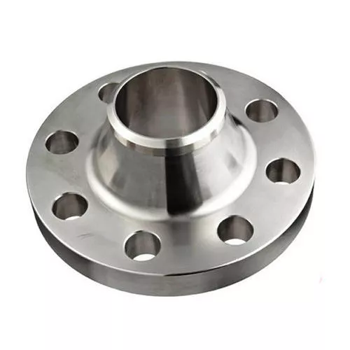
- Weld Neck Profile: Characterized by its long tapered hub that transitions smoothly from the flange to the pipe diameter. This design enhances the flange’s strength and reduces stress concentrations at the base of the hub, making it suitable for high-pressure and high-temperature applications.
- Welding Connection: The flange is butt-welded to the pipe, creating a continuous and strong connection that is ideal for critical service conditions. The weld neck design allows for a high-quality weld that is as strong as the pipe itself, ensuring the integrity of the piping system.
- Raised Face (RF) or Flat Face (FF): EN 1092-1 specifies the type of face for the flange, with the raised face being common for higher pressure ratings. The raised face concentrates the compressive force of the bolts across a smaller area, enhancing the seal’s effectiveness.
Material Specifications
EN 1092-1 specifies a range of materials for weld neck flanges, including various grades of carbon steel, alloy steel, stainless steel, and other materials suitable for specific environments and media. The material selection is critical for ensuring compatibility with the fluid, temperature, and pressure conditions of the application.
Pressure and Temperature Ratings
- The standard categorizes flanges into different pressure numbers (PN) that indicate their maximum allowable operating pressure. Weld neck flanges are available in a broad range of PNs, making them adaptable to various operational requirements.
- Temperature ratings are influenced by the flange material and design. Weld neck flanges are capable of withstanding high temperatures, making them suitable for use in heating systems, boilers, and high-temperature processing plants.
Applications
Due to their durable and leak-proof design, weld neck flanges are extensively used in demanding applications such as oil and gas pipelines, petrochemical plants, power generation facilities, and processes involving high pressure and temperatures.
Advantages
- Durability: The weld neck flange provides a strong, durable connection that can withstand significant stress and high impact.
- Leak Prevention: The high-integrity weld and the matching of the pipe and flange bores minimize turbulence and prevent leaks.
- Versatility: Suitable for a wide range of applications, pressures, and temperatures, making them a versatile choice for complex piping systems.
WHAT MEANS “TYPE 11” ACC. TO EN 1092-1?
The EN 1092-1 Type 11 flange is a designation under the European standard EN 1092-1, which specifies requirements for circular steel flanges. Type 11 refers to weld neck flanges, which are known for their robust construction and are used in various piping systems to ensure a secure, leak-proof connection. These flanges are characterized by a long tapered hub that provides important reinforcement for use in high-pressure and high-temperature environments.
DIMENSIONS & WEIGHTS OF EN 1092-1 WN FLANGES
WN FLANGE PN 6
PN 6 weld neck flange dimensions (EN 1092-1 type 11) with stud metric bolts and nuts requirements (all sizes are in millimeters unless otherwise specified)

| WN Flange DN | Flange | Neck | Raised face | Stud Bolts | Flange weight | ||||||||||
| d1 | k | D | b | h1 | d3 | s | r | h2 | d4 | f | d2 | Thread | Bolt holes | Kg | |
| 15 | 21,3 | 55 | 80 | 12 | 30 | 30 | 2,00 | 4 | 6 | 40 | 2 | 11 | M10 | 4 | 0,408 |
| 20 | 26,9 | 65 | 90 | 14 | 32 | 38 | 2,30 | 4 | 6 | 50 | 2 | 11 | M10 | 4 | 0,621 |
| 25 | 33,7 | 75 | 100 | 14 | 35 | 42 | 2,60 | 4 | 6 | 60 | 2 | 11 | M10 | 4 | 0,762 |
| 32 | 42,4 | 90 | 120 | 14 | 35 | 55 | 2,60 | 6 | 6 | 70 | 2 | 14 | M12 | 4 | 1,110 |
| 40 | 48,3 | 100 | 130 | 14 | 38 | 62 | 2,60 | 6 | 7 | 80 | 3 | 14 | M12 | 4 | 1,260 |
| 50 | 60,3 | 110 | 140 | 14 | 38 | 74 | 2,90 | 6 | 8 | 90 | 3 | 14 | M12 | 4 | 1,430 |
| 65 | 76,1 | 130 | 160 | 14 | 38 | 88 | 2,90 | 6 | 9 | 110 | 3 | 14 | M12 | 4 | 1,770 |
| 80 | 88,9 | 150 | 190 | 16 | 42 | 102 | 3,20 | 8 | 10 | 128 | 3 | 18 | M16 | 4 | 2,880 |
| 100 | 114,3 | 170 | 210 | 16 | 45 | 130 | 3,60 | 8 | 10 | 148 | 3 | 18 | M16 | 4 | 3,410 |
| 125 | 139,7 | 200 | 240 | 18 | 48 | 155 | 4,00 | 8 | 10 | 178 | 3 | 18 | M16 | 8 | 4,650 |
| 150 | 168,3 | 225 | 265 | 18 | 48 | 184 | 4,50 | 10 | 12 | 202 | 3 | 18 | M16 | 8 | 5,500 |
| 200 | 219,1 | 280 | 320 | 20 | 55 | 236 | 6,30 | 10 | 15 | 258 | 3 | 18 | M16 | 8 | 8,600 |
| 250 | 273,0 | 335 | 375 | 22 | 60 | 290 | 6,30 | 12 | 15 | 312 | 3 | 18 | M16 | 12 | 11,700 |
| 300 | 323,9 | 395 | 440 | 22 | 62 | 342 | 7,10 | 12 | 15 | 365 | 4 | 22 | M20 | 12 | 15,300 |
| 350 | 355,6 | 445 | 490 | 22 | 62 | 385 | 7,10 | 12 | 15 | 415 | 4 | 22 | M20 | 12 | 20,300 |
| 400 | 406,4 | 495 | 540 | 22 | 65 | 438 | 7,10 | 12 | 15 | 465 | 4 | 22 | M20 | 16 | 23,100 |
| 450 | 457,0 | 550 | 595 | 22 | 65 | 492 | 7,10 | 12 | 15 | 520 | 4 | 22 | M20 | 16 | 27,000 |
| 500 | 508,0 | 600 | 645 | 24 | 68 | 538 | 7,10 | 12 | 15 | 570 | 4 | 22 | M20 | 20 | 30,800 |
| 600 | 610,0 | 705 | 755 | 30 | 70 | 640 | 7,10 | 12 | 16 | 670 | 5 | 26 | M24 | 20 | 44,000 |
| 700 | 711,0 | 810 | 860 | 30 | 76 | 740 | 8,00 | 12 | 16 | 775 | 5 | 26 | M24 | 24 | 53,700 |
| 800 | 813,0 | 920 | 975 | 30 | 76 | 842 | 8,00 | 12 | 16 | 880 | 5 | 30 | M27 | 24 | 64,400 |
| 900 | 914,0 | 1020 | 1075 | 34 | 78 | 942 | 8,00 | 12 | 16 | 980 | 5 | 30 | M27 | 24 | 79,200 |
| 1000 | 1016,0 | 1120 | 1175 | 38 | 82 | 1045 | 8,00 | 16 | 16 | 1080 | 5 | 30 | M27 | 28 | 98,600 |
| 1200 | 1219,0 | 1340 | 1405 | 42 | 104 | 1248 | 8,80 | 16 | 20 | 1295 | 5 | 33 | M30 | 32 | 152,000 |
| 1400 | 1422,0 | 1560 | 1630 | 56 | 114 | 1452 | 8,80 | 16 | 20 | 1510 | 5 | 36 | M33 | 36 | 246,000 |
| 1600 | 1626,0 | 1760 | 1830 | 63 | 119 | 1655 | 10,00 | 16 | 20 | 1710 | 5 | 36 | M33 | 40 | 309,000 |
| 1800 | 1829,0 | 1970 | 2045 | 69 | 133 | 1855 | 11,00 | 16 | 20 | 1920 | 5 | 39 | M36 | 44 | 400,000 |
| 2000 | 2032,0 | 2180 | 2265 | 74 | 146 | 2058 | 12,50 | 16 | 25 | 2125 | 5 | 42 | M39 | 48 | 516,000 |
| 2200 | 2235,0 | 2390 | 2475 | 81 | 154 | 2260 | 14,00 | 18 | 25 | 2335 | 5 | 42 | M39 | 52 | 645,000 |
| 2400 | 2438,0 | 2600 | 2685 | 87 | 168 | 2462 | 15,00 | 18 | 25 | 2545 | 5 | 42 | M39 | 56 | 786,000 |
| 2600 | 2620,0 | 2810 | 2905 | 91 | 175 | 2665 | 16,00 | 18 | 25 | 2750 | 5 | 48 | M45 | 60 | 1.021,000 |
| 2800 | 2820,0 | 3020 | 3115 | 101 | 188 | 2865 | 17,00 | 18 | 30 | 2960 | 5 | 48 | M45 | 64 | 1.256,000 |
| 3000 | 3020,0 | 3220 | 3315 | 102 | 192 | 3068 | 20,00 | 18 | 30 | 3160 | 5 | 48 | M45 | 68 | 1.404,000 |
| 3200 | 3220,0 | 3430 | 3525 | 106 | 202 | 3272 | 20,00 | 20 | 30 | 3370 | 5 | 48 | M45 | 72 | 1.617,000 |
| 3400 | 3420,0 | 3640 | 3735 | 110 | 214 | 3475 | 22,00 | 20 | 35 | 3580 | 5 | 48 | M45 | 76 | 1.877,000 |
| 3600 | 3620,0 | 3860 | 3970 | 124 | 229 | 3678 | 22,00 | 20 | 35 | 3790 | 5 | 56 | M52 | 80 | 2.366,000 |
WN FLANGE PN 10
PN 10 weld neck flange dimensions (EN 1092-1 type 11) with stud metric bolts and nuts requirements (all sizes are in millimeters unless otherwise specified)
| WN Flange DN | Flange | Neck | Raised face | Stud Bolts | Flange weight | ||||||||||
| d1 | k | D | b | h1 | d3 | s | r | h2 | d4 | f | d2 | Thread | Bolt holes | Kg | |
| 200 | 219,1 | 295 | 340 | 24 | 62 | 234 | 6,30 | 10 | 16 | 268 | 3 | 22 | M20 | 8 | 11,600 |
| 250 | 273,0 | 350 | 395 | 26 | 68 | 292 | 6,30 | 12 | 16 | 320 | 3 | 22 | M20 | 12 | 15,800 |
| 300 | 323,9 | 400 | 445 | 26 | 68 | 342 | 7,10 | 12 | 16 | 370 | 4 | 22 | M20 | 12 | 18,300 |
| 350 | 355,6 | 460 | 505 | 26 | 68 | 385 | 7,10 | 12 | 16 | 430 | 4 | 22 | M20 | 16 | 25,300 |
| 400 | 406,4 | 515 | 565 | 26 | 72 | 440 | 7,10 | 12 | 16 | 482 | 4 | 26 | M24 | 16 | 30,600 |
| 450 | 457,0 | 565 | 615 | 28 | 72 | 488 | 7,10 | 12 | 16 | 532 | 4 | 26 | M24 | 20 | 35,100 |
| 500 | 508,0 | 620 | 670 | 28 | 75 | 542 | 7,10 | 12 | 16 | 585 | 4 | 26 | M24 | 20 | 40,500 |
| 600 | 610,0 | 725 | 780 | 30 | 82 | 642 | 8,00 | 12 | 18 | 685 | 5 | 30 | M27 | 20 | 52,900 |
| 700 | 711,0 | 840 | 895 | 35 | 85 | 746 | 8,80 | 12 | 18 | 800 | 5 | 30 | M27 | 24 | 75,800 |
| 800 | 813,0 | 950 | 1015 | 38 | 96 | 850 | 8,80 | 12 | 18 | 905 | 5 | 33 | M30 | 24 | 102,000 |
| 900 | 914,0 | 1050 | 1115 | 38 | 99 | 950 | 12,50 | 12 | 20 | 1005 | 5 | 33 | M30 | 28 | 121,000 |
| 1000 | 1016,0 | 1160 | 1230 | 44 | 105 | 1052 | 12,50 | 16 | 20 | 1110 | 5 | 36 | M33 | 28 | 161,000 |
| 1200 | 1219,0 | 1380 | 1455 | 55 | 132 | 1256 | 12,50 | 16 | 25 | 1330 | 5 | 39 | M36 | 32 | 258,000 |
| 1400 | 1422,0 | 1590 | 1675 | 65 | 143 | 1460 | 14,20 | 16 | 25 | 1535 | 5 | 42 | M39 | 36 | 371,000 |
| 1600 | 1626,0 | 1820 | 1915 | 75 | 159 | 1666 | 16,00 | 16 | 25 | 1760 | 5 | 48 | M45 | 40 | 547,000 |
| 1800 | 1829,0 | 2020 | 2115 | 85 | 175 | 1868 | 17,50 | 16 | 30 | 1960 | 5 | 48 | M45 | 44 | 691,000 |
| 2000 | 2032,0 | 2230 | 2325 | 90 | 186 | 2072 | 17,50 | 16 | 30 | 2170 | 5 | 48 | M45 | 48 | 830,000 |
| 2200 | 2235,0 | 2440 | 2550 | 100 | 202 | 2275 | 20,00 | 18 | 35 | 2370 | 5 | 56 | M52 | 52 | 1.073,000 |
| 2400 | 2438,0 | 2650 | 2760 | 110 | 218 | 2478 | 22,20 | 18 | 35 | 2570 | 5 | 56 | M52 | 56 | 1.329,000 |
| 2600 | 2620,0 | 2850 | 2960 | 110 | 224 | 2680 | 25,00 | 18 | 40 | 2780 | 5 | 56 | M52 | 60 | 1.574,000 |
| 2800 | 2820,0 | 3070 | 3180 | 124 | 244 | 2882 | 25,00 | 18 | 40 | 3000 | 5 | 56 | M52 | 64 | 1.987,000 |
| 3000 | 3020,0 | 3290 | 3405 | 132 | 257 | 3085 | 32,00 | 18 | 45 | 3210 | 5 | 62 | M56 | 68 | 2.476,000 |
WN FLANGE PN 16
PN 16 weld neck flange dimensions (EN 1092-1 type 11) with stud metric bolts and nuts requirements (all sizes are in millimeters unless otherwise specified)
| WN Flange DN | Flange | Neck | Raised face | Stud Bolts | Flange weight | ||||||||||
| d1 | k | D | b | h1 | d3 | s | r | h2 | d4 | f | d2 | Thread | Bolt holes | Kg | |
| 15 | 21,3 | 65 | 95 | 16 | 38 | 32 | 2,00 | 4 | 6 | 45 | 2 | 14 | M12 | 4 | 0,678 |
| 20 | 26,9 | 75 | 105 | 18 | 40 | 40 | 2,30 | 4 | 6 | 58 | 2 | 14 | M12 | 4 | 0,768 |
| 25 | 33,7 | 85 | 115 | 18 | 40 | 46 | 2,60 | 4 | 6 | 68 | 2 | 14 | M12 | 4 | 1,090 |
| 32 | 42,4 | 100 | 140 | 18 | 42 | 56 | 2,60 | 6 | 6 | 78 | 2 | 18 | M16 | 4 | 1,300 |
| 40 | 48,3 | 110 | 150 | 18 | 45 | 64 | 2,60 | 6 | 7 | 88 | 3 | 18 | M16 | 4 | 1,910 |
| 50 | 60,3 | 125 | 165 | 18 | 45 | 74 | 2,9 | 6 | 8 | 102 | 3 | 18 | M16 | 4 | 2,530 |
| 65 | 76,1 | 145 | 185 | 18 | 45 | 92 | 2,9 | 6 | 10 | 122 | 3 | 18 | M16 | 4 | 3,030 |
| 80 | 88,9 | 160 | 200 | 20 | 50 | 105 | 3,2 | 6 | 10 | 138 | 3 | 18 | M16 | 8 | 3,920 |
| 100 | 114,3 | 180 | 220 | 20 | 52 | 131 | 3,6 | 8 | 12 | 158 | 3 | 18 | M16 | 8 | 4,620 |
| 125 | 139,7 | 210 | 250 | 22 | 55 | 156 | 4,0 | 8 | 12 | 188 | 3 | 18 | M16 | 8 | 6,300 |
| 150 | 168,3 | 240 | 285 | 22 | 55 | 184 | 4,5 | 10 | 12 | 212 | 3 | 22 | M20 | 8 | 7,810 |
| 200 | 219,1 | 295 | 340 | 24 | 62 | 235 | 6,30 | 10 | 16 | 268 | 3 | 22 | M20 | 12 | 11,500 |
| 250 | 273,0 | 355 | 405 | 26 | 70 | 292 | 6,30 | 12 | 16 | 320 | 3 | 26 | M24 | 12 | 16,700 |
| 300 | 323,9 | 410 | 460 | 28 | 78 | 344 | 7,10 | 12 | 16 | 378 | 4 | 26 | M24 | 12 | 22,100 |
| 350 | 355,6 | 470 | 520 | 30 | 82 | 390 | 8,00 | 12 | 16 | 438 | 4 | 26 | M24 | 16 | 32,800 |
| 400 | 406,4 | 525 | 580 | 32 | 85 | 445 | 8,00 | 12 | 16 | 490 | 4 | 30 | M27 | 16 | 41,100 |
| 450 | 457,0 | 585 | 640 | 34 | 83 | 490 | 8,00 | 12 | 16 | 550 | 4 | 30 | M27 | 20 | 48,500 |
| 500 | 508 | 650 | 715,0 | 36 | 84 | 548 | 8,0 | 12 | 16 | 610 | 4 | 33 | M30 | 20 | 63,400 |
| 600 | 610 | 770 | 840,0 | 40 | 88 | 670 | 10,0 | 12 | 18 | 725 | 5 | 36 | M33 | 20 | 96,000 |
| 700 | 711 | 840 | 910,0 | 40 | 104 | 755 | 10,0 | 12 | 18 | 795 | 5 | 36 | M33 | 24 | 96,500 |
| 800 | 813 | 950 | 1025,0 | 41 | 108 | 855 | 12,5 | 12 | 20 | 900 | 5 | 39 | M36 | 24 | 122,000 |
| 900 | 914 | 1050 | 1125,0 | 48 | 118 | 955 | 12,5 | 12 | 20 | 1000 | 5 | 39 | M36 | 28 | 155,000 |
| 1000 | 1016 | 1170 | 1255,0 | 59 | 137 | 1058 | 12,5 | 16 | 22 | 1115 | 5 | 42 | M39 | 28 | 233,000 |
| 1200 | 1219 | 1390 | 1485,0 | 78 | 160 | 1262 | 14,2 | 16 | 30 | 1330 | 5 | 48 | M45 | 32 | 390,000 |
| 1400 | 1422 | 1590 | 1685,0 | 84 | 177 | 1465 | 16,0 | 16 | 30 | 1530 | 5 | 48 | M45 | 36 | 495,000 |
| 1600 | 1626 | 1820 | 1930,0 | 102 | 204 | 1668 | 17,5 | 16 | 35 | 1750 | 5 | 56 | M52 | 40 | 760,000 |
| 1800 | 1829 | 2020 | 2130,0 | 110 | 218 | 1870 | 20,0 | 16 | 35 | 1950 | 5 | 56 | M52 | 44 | 929,000 |
| 2000 | 2032 | 2230 | 2345,0 | 124 | 238 | 2072 | 22,0 | 16 | 40 | 2150 | 5 | 62 | M56 | 48 | 1.185,000 |
WN FLANGE PN 25
PN 25 weld neck flange dimensions (EN 1092-1 type 11) with stud metric bolts and nuts requirements (all sizes are in millimeters unless otherwise specified)
| WN Flange DN | Flange | Neck | Raised face | Stud Bolts | Flange weight | ||||||||||
| d1 | k | D | b | h1 | d3 | s | r | h2 | d4 | f | d2 | Thread | Bolt holes | Kg | |
| 200 | 219,1 | 310 | 360 | 30 | 80 | 244 | 6,3 | 10 | 16 | 278 | 3 | 26 | M24 | 12 | 17,100 |
| 250 | 273 | 370 | 425 | 32 | 88 | 298 | 7,1 | 12 | 18 | 335 | 3 | 30 | M27 | 12 | 24,300 |
| 300 | 323,9 | 430 | 485 | 34 | 92 | 352 | 8,0 | 12 | 18 | 395 | 4 | 30 | M27 | 16 | 31,800 |
| 350 | 355,6 | 490 | 555 | 38 | 100 | 398 | 8,0 | 12 | 20 | 450 | 4 | 33 | M30 | 16 | 48,800 |
| 400 | 406,4 | 550 | 620 | 40 | 110 | 452 | 8,8 | 12 | 20 | 505 | 4 | 36 | M33 | 16 | 63,300 |
| 450 | 457 | 600 | 670 | 46 | 110 | 500 | 8,8 | 12 | 20 | 550 | 4 | 36 | M33 | 20 | 76,000 |
| 500 | 508 | 660 | 730 | 48 | 125 | 558 | 10,0 | 12 | 20 | 615 | 4 | 36 | M33 | 20 | 97,000 |
| 600 | 610 | 770 | 845 | 48 | 125 | 660 | 11,0 | 12 | 20 | 720 | 5 | 39 | M36 | 20 | 121,000 |
| 700 | 711 | 875 | 960 | 50 | 129 | 760 | 14,2 | 12 | 20 | 820 | 5 | 42 | M39 | 24 | 155,000 |
| 800 | 813 | 990 | 1085 | 53 | 138 | 864 | 16,0 | 12 | 22 | 930 | 5 | 48 | M45 | 24 | 205,000 |
| 900 | 914 | 1090 | 1185 | 57 | 148 | 968 | 17,5 | 12 | 24 | 1030 | 5 | 48 | M45 | 28 | 249,000 |
| 1000 | 1016 | 1210 | 1320 | 63 | 160 | 1070 | 20,0 | 16 | 24 | 1140 | 5 | 56 | M52 | 28 | 338,000 |
WN FLANGE PN 40
PN 40 weld neck flange dimensions (EN 1092-1 type 11) with stud metric bolts and nuts requirements (all sizes are in millimeters unless otherwise specified)
| WN Flange DN | Flange | Neck | Raised face | Stud Bolts | Flange weight | ||||||||||
| d1 | k | D | b | h1 | d3 | s | r | h2 | d4 | f | d2 | Thread | Bolt holes | Kg | |
| 15 | 21,3 | 65 | 95 | 16 | 38 | 32 | 2,00 | 4 | 6 | 45 | 2 | 14 | M12 | 4 | 0,768 |
| 20 | 26,9 | 75 | 105 | 18 | 40 | 40 | 2,30 | 4 | 6 | 58 | 2 | 14 | M12 | 4 | 1,090 |
| 25 | 33,7 | 85 | 115 | 18 | 40 | 46 | 2,60 | 4 | 6 | 68 | 2 | 14 | M12 | 4 | 1,300 |
| 32 | 42,4 | 100 | 140 | 18 | 42 | 56 | 2,60 | 6 | 6 | 78 | 2 | 18 | M16 | 4 | 1,910 |
| 40 | 48,3 | 110 | 150 | 18 | 45 | 64 | 2,60 | 6 | 7 | 88 | 3 | 18 | M16 | 4 | 2,150 |
| 50 | 60,3 | 125 | 165 | 20 | 48 | 75 | 2,90 | 6 | 8 | 102 | 3 | 18 | M16 | 4 | 2,850 |
| 65 | 76,1 | 145 | 185 | 22 | 52 | 90 | 2,90 | 6 | 10 | 122 | 3 | 18 | M16 | 8 | 3,680 |
| 80 | 88,9 | 160 | 200 | 24 | 58 | 105 | 3,20 | 8 | 12 | 138 | 3 | 18 | M16 | 8 | 4,780 |
| 100 | 114,3 | 190 | 235 | 24 | 65 | 134 | 3,60 | 8 | 12 | 162 | 3 | 22 | M20 | 8 | 6,460 |
| 125 | 139,7 | 220 | 270 | 26 | 68 | 162 | 4,00 | 8 | 12 | 188 | 3 | 26 | M24 | 8 | 8,860 |
| 150 | 168,3 | 250 | 300 | 28 | 75 | 192 | 4,50 | 10 | 12 | 218 | 3 | 26 | M24 | 8 | 11,700 |
| 200 | 219,1 | 320 | 375 | 34 | 88 | 244 | 6,30 | 10 | 16 | 285 | 3 | 30 | M27 | 12 | 21,000 |
| 250 | 273,0 | 385 | 450 | 38 | 105 | 306 | 7,10 | 12 | 18 | 345 | 3 | 33 | M30 | 12 | 34,200 |
| 300 | 323,9 | 450 | 515 | 42 | 115 | 362 | 8,00 | 12 | 18 | 410 | 4 | 33 | M30 | 16 | 47,600 |
| 350 | 355,6 | 510 | 580 | 46 | 125 | 408 | 8,80 | 12 | 20 | 465 | 4 | 36 | M33 | 16 | 69,300 |
| 400 | 406,4 | 585 | 660 | 50 | 135 | 462 | 11,00 | 12 | 20 | 535 | 4 | 39 | M36 | 16 | 98,000 |
| 450 | 457,0 | 610 | 685 | 57 | 135 | 500 | 12,50 | 12 | 20 | 560 | 4 | 39 | M36 | 20 | 105,000 |
| 500 | 508,0 | 670 | 755 | 57 | 140 | 562 | 14,20 | 12 | 20 | 615 | 4 | 42 | M39 | 20 | 130,000 |
| 600 | 610,0 | 795 | 890 | 72 | 150 | 666 | 16,00 | 12 | 20 | 735 | 5 | 48 | M45 | 20 | 209,000 |
TOLERANCE EN1092-1 WN FLANGES
The EN 1092-1 standard specifies requirements for circular steel flanges, including dimensions, tolerances, and marking for flanges within the size range of DN 10 to DN 4000 and pressure designations from PN 2.5 to PN 400. However, the standard encompasses a wide range of flange types and configurations, making it challenging to summarize all tolerance values universally for all weld neck flanges within a brief response. The detailed tolerance values are specifically outlined in the EN 1092-1 standard document and can vary depending on the flange size (DN), pressure class (PN), and other factors.
While we can’t provide the exhaustive list of tolerance values from the EN 1092-1 standard directly due to the complexity and breadth of the information, below are examples of types of tolerances you would typically find in the standard for weld neck flanges (Type 11):
Diameter of Bolt Circle (P):
Tolerance values ensure that bolt holes align correctly for all mating flanges, facilitating proper bolting without strain.
Diameter of Bolt Holes (D):
Bolt holes are slightly larger than the nominal bolt size to accommodate variations in bolt size and allow for easier assembly.
Flange Thickness (C):
The tolerance of flange thickness accounts for manufacturing variations while ensuring the flange can withstand the designated pressure.
Outside Diameter of Flange (D):
This tolerance ensures that the flange fits within the mating equipment or pipework correctly, accounting for manufacturing variations.
Flange Hub Diameter at Base and Length (E and F):
Tolerances here ensure the proper fit between the flange and the pipe, especially important for the weld neck where the transition from pipe to flange needs to be smooth to avoid turbulence and stress concentrations.
Bore Diameter (B):
Critical for matching the inside diameter of the flange to the outside diameter of the pipe, ensuring a smooth flow path and proper alignment.
For specific tolerance values, the reader must refer to the tables and annexes of the EN 1092-1 standard, as these values can vary significantly across the range of sizes and pressure classes covered. Engineers and designers rely on these details to ensure that fabricated flanges and the resulting piping assemblies meet the required performance and safety criteria under operating conditions. Access to the full EN 1092-1 standard through a standards organization or industry body is essential for obtaining accurate and applicable tolerance information for a given application.


2 Responses
PN 40 DN 700 NO OF BOLT 24 d2 -36 D-900
PDC/K????????????????????????????
PLEASE PROVIDE ME WITH YOUR PRICES FOR PN6 NECK FLANGES AS FOLLOWS:
DN25 QTY 20
DN40 QTY 4
DN65 QTY 2
DN80 QTY 29
DN100 QTY 2
& PN10 SIZE DN65 QTY 6 PCS
MARWAN SALEH
00962797983715
E-MAIL marwanslh74@gmail.com